EP0110276A2 - Dispositif de pompe à perfusion - Google Patents
Dispositif de pompe à perfusion Download PDFInfo
- Publication number
- EP0110276A2 EP0110276A2 EP83111601A EP83111601A EP0110276A2 EP 0110276 A2 EP0110276 A2 EP 0110276A2 EP 83111601 A EP83111601 A EP 83111601A EP 83111601 A EP83111601 A EP 83111601A EP 0110276 A2 EP0110276 A2 EP 0110276A2
- Authority
- EP
- European Patent Office
- Prior art keywords
- pumping chamber
- outlet
- valve seat
- inlet
- fluid passage
- Prior art date
- Legal status (The legal status is an assumption and is not a legal conclusion. Google has not performed a legal analysis and makes no representation as to the accuracy of the status listed.)
- Withdrawn
Links
Images


Classifications
-
- A—HUMAN NECESSITIES
- A61—MEDICAL OR VETERINARY SCIENCE; HYGIENE
- A61M—DEVICES FOR INTRODUCING MEDIA INTO, OR ONTO, THE BODY; DEVICES FOR TRANSDUCING BODY MEDIA OR FOR TAKING MEDIA FROM THE BODY; DEVICES FOR PRODUCING OR ENDING SLEEP OR STUPOR
- A61M5/00—Devices for bringing media into the body in a subcutaneous, intra-vascular or intramuscular way; Accessories therefor, e.g. filling or cleaning devices, arm-rests
- A61M5/14—Infusion devices, e.g. infusing by gravity; Blood infusion; Accessories therefor
- A61M5/142—Pressure infusion, e.g. using pumps
- A61M5/14212—Pumping with an aspiration and an expulsion action
- A61M5/14216—Reciprocating piston type
-
- Y—GENERAL TAGGING OF NEW TECHNOLOGICAL DEVELOPMENTS; GENERAL TAGGING OF CROSS-SECTIONAL TECHNOLOGIES SPANNING OVER SEVERAL SECTIONS OF THE IPC; TECHNICAL SUBJECTS COVERED BY FORMER USPC CROSS-REFERENCE ART COLLECTIONS [XRACs] AND DIGESTS
- Y10—TECHNICAL SUBJECTS COVERED BY FORMER USPC
- Y10S—TECHNICAL SUBJECTS COVERED BY FORMER USPC CROSS-REFERENCE ART COLLECTIONS [XRACs] AND DIGESTS
- Y10S128/00—Surgery
- Y10S128/12—Pressure infusion
-
- Y—GENERAL TAGGING OF NEW TECHNOLOGICAL DEVELOPMENTS; GENERAL TAGGING OF CROSS-SECTIONAL TECHNOLOGIES SPANNING OVER SEVERAL SECTIONS OF THE IPC; TECHNICAL SUBJECTS COVERED BY FORMER USPC CROSS-REFERENCE ART COLLECTIONS [XRACs] AND DIGESTS
- Y10—TECHNICAL SUBJECTS COVERED BY FORMER USPC
- Y10T—TECHNICAL SUBJECTS COVERED BY FORMER US CLASSIFICATION
- Y10T137/00—Fluid handling
- Y10T137/7722—Line condition change responsive valves
- Y10T137/7837—Direct response valves [i.e., check valve type]
- Y10T137/7904—Reciprocating valves
Definitions
- This invention relates to a pumping device for administering intravenous and intra-arterial liquids. More particularly, this invention relates to a pumping device which includes a valved pumping chamber wherein the inlet and outlet valves are magnetically operable.
- infusion therapy system as a method of treating patients is well known in the prior art.
- These systems provide health care personnel with the means to administer medication, provide nutrition, prevent dehydration or assure infusion of necessary fluids into the body of a patient.
- Sterility in infusion therapy is presently maintained by using disposable devices which are sterilized before use and discarded after use thus eliminating the need for expensive, complex, and often uncertain resterilization.
- the rising cost of health care is a matter of substantial concern to those in need of medical treatment. Any new development must therefore be conceived with simplicity and low cost in.mind.
- the dosage of medication administered by infusion therapy varies over a wide range of values spread over an even wider range of times.
- the prescribed dosage of medication per unit of time may be translated into a flow rate for an infusion pump system.
- Very low flow rates are often characterized by pulsatile spurts of liquid through the infusion delivery system into the patient.
- This pulsatile flow has disadvantages in that the lumen in the needle used during venpuncture may become closed in the intervals between the spurts of fluid. This closing is caused by blood flowing back into the infusion delivery system through the venipuncture.
- the ideal situation is therefore to provide a uniform continuous flow of medication into a patient at the lowest possible rate settings for the infusion system employed. This is particularly important with medication having a short half-life such as Oxytocin as sold by Abbott Laboratories. In these situations the infusion system must maintain an appropriate level of medication within the patient's body concurrently with the drop in potency of the medication.
- An examination of the fluid mechanics of an infusion fluid delivery system indicates that the fluid pressure within a patient's blood stream works against the intravenous or intra-arterial infusion of fluid.
- the blood pressure of the patient also has a tendency to cause reflux of blood back into the needle as indicated earlier. If blood remains in the lumen it has a tendency to clot and thereby cause a blockage to the intravenous or intra-arterial infusion of fluid.
- Such a device would also provide a uniform and constant one-way flow to assure a continuous supply of medication or fluid matched to the treatment needs of a patient no matter how small or how large those needs may be.
- infusion delivery systems must be designed to be quickly operational in order to allow health care personel the greatest amount of time to administer to more important treatment needs of a particular patient.
- Proper pump priming is another area of concern for health care personnel. Any pump used in an infusion fluid administration system should both be easy to prime and clearly able to show positive visual indication of having been primed. Additionally, it is desirable to give an indication to the user that all components are assembled correctly. The appearance of a signal, the positioning of components without the exertion of undue force and proper orientation of internal parts supplies the user with the confidence that the infusion administration system is properly set up for operation. Once properly positioned in the pump actuator, primed and operating, there is also a need to give a positive visual indication of operation. Infusion fluids are often clear and when flowing give no positive visual perception of movement. Many pumps used in infusion flow control systems found in the prior art have been hidden from view by operating means or flow controllers. It is therefore an advantage of this invention to provide a pump system whose operation at all but the very smallest flow rates can be visually verified by health care personnel.
- a further advantage is the provision of an intravenous or intra-arterial delivery system which prevents the flow of air into the patient through a venipuncture site during administration of intravenous or intra-arterial fluid as well as when the source of infusion fluid is depleted.
- the infusion pumping system disclosed herein utilizes a valved pumping chamber.
- the outlet valve must be biased closed with the attendant need to defeat the bias on the outlet valve during priming.
- the utilization of magnetically biased valves with a pumping chamber enables a biased outlet valve to prevent the pumping of air when in operation and free flow priming or gravity operation when the valved pumping chamber is removed from the magnetic field.
- ferro-magnetic balls, resilient rubber valve seats and permanently mounted magnets within the pump housing provides a method for a highly reproducible bias. Two such ferro-magnetic ball valve assemblies may be used: one for the inlet and one for the outlet.
- valves become fluid pressure actuated. Specifically, the inlet valve will not open until the pumping chamber internal pressure is less than the infusion fluid source head pressure, thus preventing backflow of fluid. Similarly, the outlet valve will not open until the pumping chamber pressure exceeds the downstream pressure caused by the blood pressure of the patient, system filters and flow devices. Backflow or reflux of blood into the needle will thereby be prevented. The elimination of backflow or reflux of blood into the needle prevents the closing of the lumen in the needle and the resulting disabling of the infusion administration system.
- Mechanically operated valving systems associated with pumping chambers in infusion delivery systems must compromise in this regard.
- the timing of mechanically operated valves must be carefully programmed either electrically or mechanically to produce the requisite operating differential pressure at the highest level of the broad range of intravenous or upstream and intra-arterial or downstream pressures.
- Higher pressures of pump output may cause a bolus of solution to flow through the venipuncture into the patient.
- Lower pressures of pump output may permit backflow of the blood of the patient into the lumen of the venipuncture needle. Consequently, whatever pressure for pump output is selected, it is easily defeated by near zero upstream pressure of an open infusion system on the low end and maximum downstream operating pressure on the high end.
- magnets to bias the valves controlling fluid flow provides the user the distinct advantage of being able to selectively remove valve bias by cancelling the magnetic field or removing the magnetically biased valves from the influence of the controlling magnets.
- the disclosed system provides a second capability for gravity operation where a manually adjustable clamp can be used to vary the flow rate of medication into a patient.
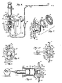
- valved pumping chamber generally 99 is shown in FIGURE 1 is used in an infusion pump system generally 39.
- the inlet port 11 of the valved pumping chamber 99 is mounted downstream from an air trap 98 and interconnected by upstream tubing 10 to a fluid source 35 through drip chamber 43.
- the outlet port 23 of the valved pumping chamber 99 is interconnected by downstream tubing 27 to suitable means for venipuncture such as a catheter or needle 94.
- the usual flow control tubing clamp 92 and Y-reseal site 55 are attached to tubing 27.
- FIGURE 2 shows the valved pumping chamber 99 mounted in pump actuator generally 34, the magnetically permeable inlet flow restricting means or ball 13 is magnetically biased against inlet valve seat 12, thus making it a flow restricting means.
- magnetically permeable outlet flow restricting means or ball 25 which similarly serves as a flow restricting means is magnetically biased against outlet valve seat 24.
- Post members 14 and 26 extend transversely across the fluid passages containing balls 13 and 25 and valve seats 12 and 24. The post members 14 and 26 act as restraining means to prevent balls 13 and 25 from moving out of close proximity with respect to valve seats 12 and 24.
- valved pumping chamber 99 and compartment 51 for accommodating the valved pumping chamber 99 are positioned so that they are transverse to the line of travel A-A of plunger member 22 with diaphragm 21 being centrally contacted thereby.
- step-like compartment 51 being composed of side slots 84 and 86 on either side of opening 85.
- Side slots 84 and 86 receive the oppositely extending outward portions of rigid wall 18 (FIGURE 7).
- Opening 85 receives the diaphragmed portion of the valved cassette 99.
- Plunger member 22 moves transversely to the long axis of opening 85.
- mechanical mounting means are provided in the pump actuator 34 which have the same basic external configuration as the valved pumping chamber 99.
- the cavity 30 within the pressure chamber 16 of valved pumping chamber 99 is interconnected to the upstream tubing 10 of the infusion delivery system 39 by inlet port 11 and interconnected to the downstream tubing 27 of the infusion delivery system 39 by outlet port 23.
- FIGURE 2 shows in more detail the valving arrangement of pumping chamber 99.
- Port 11 is in fluid connection with inlet valve assembly 95.
- inlet valve seat 12 contains a bore 44, the opening and closing of which is accomplished by the action of ball 13 which affords a flow restricting means wherein ball 13 moves along a path 17, the limits of which are seat 12 and post member 14.
- ball 13 rests against post member 14 an open path is provided whereas a closed flow path is afforded when ball 13 is biased against inlet valve seat 12.
- post member 14 is in the nature of a restraining means to maintain ball 13 in close proximity to valve seat 12.
- Pressure chamber 16 and diaphragm 21 provide a cavity 30 for the infusion fluid.
- valved pumping chamber 99 Disposed at the opposite end of valved pumping chamber 99 is outlet valve assembly 96 with a valve seat 24 containing a bore 45 which is opened and closed in a manner similar to the bore 44 in inlet valve seat 12. This is accomplished by the action of ball 25 which affords a flow restricting means when moved along path 20, the limits of which are seat 24 and post member 26. The open position is described by ball 25 resting against post member 26 while the closed position biases ball 25 against valve seat 24. Extending beyond post member 26 is outlet port 23 which provides a connection for tubing 27. Disposed in pump actuator housing 56 is a limit switch 29 to signal proper seating of valved pumping chamber 99 in pump actuator 34.
- FIGURE 3 the mounting covers 52, 53 of pump actuator 34 (FIGURE 1) for magnets 46 and 47 have been partially removed to show the orientation of the magnets which provide a magnetic field 15 at the inlet valve assembly 95 and a magnetic field 28 at the outlet valve assembly 96 of the valved pumping chamber 99.
- the ends 60 and 61 of the magnets 46 and 47, respectively adjacent ball 13 are spaced a greater distance apart than the ends 62 and 63 of the magnets 46 and 47 respectively adjacent ball 25. Accordingly, a greater magnetic effect will be produced on ball 25 in holding it against valve seat 24.
- Magnets 46 and 47 are set into slots (not shown) molded or machined in the covers 52 and 53 mounted on pump actuator housing 56.
- FIGURES 4 and 4a depict the relative location of balls 13 and 25 and plunger member 22 during pump operation.
- FIGURE 4 depicts the cavity 30 within valved pumping chamber 99 at its smallest volume. This condition occurs as fluid is flowing from the cavity 30 through outlet valve assembly 96 into downstream tubing 27.
- FIGURE 4a depicts the cavity 30 within valved pumping chamber 99 at its maximum volume. This condition occurs as fluid is flowing into the cavity 30 through inlet valve assembly 95 from upstream tubing 10.
- FIGURES 4 and 4a read together with FIGURE 8 illustrate that rigid wall 18 and pump chamber portion 16 combine to form base member 80. Cavity 30 is described by pump chamber 16 and diaphragm 21. Rigid wall 18 provides the surfaces for locating and retaining the valved pumping chamber 99 in compartment 51 of pump actuator 34 (FIGURES 1, 3 and 6)
- inlet valve assembly 95 and outlet valve assembly 96 are mounted on and in fluid connection with pump chamber 16.
- a retainer 31 which provides a flexible diaphragm 21 (FIGURE 2), thus defining a cavity 30 (FIGURE 2).
- Fluid enters the cavity 30 (FIGURE 2) of the closed pressure chamber 16 by passing through inlet port 11 into inlet valve assembly 95, more specifically through the bore 44 of the inlet valve seat 12 past the inlet flow restricting means 13.
- FIGURE 6 illustrates the embodiment of the invention wherein a syringe 36 is the source of fluid rather than container 35.
- the syringe 36 is connected directly or by fluid connecting means to air trap 98. This connection is effected by the frictional fitment of the nozzle portion 40 of the syringe 36 into an orifice 48 in air trap 98.
- the entire valved pumping chamber 99 is positioned within the pump actuator 34 as previously described in FIGURES 2 and 3 with the same reference numerals indicating the same parts.
- closed pressure chamber 16 of valved pumping chamber 99 will be fabricated in three parts.
- diaphragm 21 will be placed between base member 80 and retainer 31.
- the outer portion 82 of diaphragm 21 will be frictionally engaged in an interior annular compartment of base member 80 and retainer 31.
- the flexible wall portion 79 of diaphragm 21 will be accessible through opening 81 in retainer 31.
- the base member 80 will be sealed to retaining member 31 by means of ultrasonic welding or a suitable adhesive. This results in a pumping cavity 30.
- inlet valve assembly 95 and outlet valve assembly 96 in fluid communication with cavity 30 described within the combination of base member 80, diaphragm 21 and retainer 31.
- This combination of elements becomes valved pumping chamber 99.
- Upstream tubing 10 and downstream tubing 27 may be connected to ports 11 and 23 respectively. If required, an adapter 91 may be used to effect fluid-tight connections.
- the inlet and outlet tubing 10 and 27 will form a portion of an infusion pump system 39 with inlet tubing 10 being connected through an air trap such as 98 to a standard source of I.V. fluid 35 which includes a drip chamber 43.
- Outlet tubing 27 will be connected to a catheter or needle 94 as seen in FIGURE 1.
- FIGURE 8 is another alternative embodiment showing a flapper valve 54 used in place of the magnetically permeable ball 13 and valve seat 12 composing inlet valve assembly 95 as seen in FIGURE 2.
- the flapper valve 54 consists of a moving member 49 which is responsive to hydraulic pressure within closed pressure chamber 16. Fluid communication between upstream tubing 10 and closed pressure chamber 16 is prevented by seating of moving member 49 onto stop 50.
- the same reference characters have been employed to designate components having the same function, construction and relative location as in FIGURES 1-7.
- FIGURE 9 is still another alternative embodiment showing a syringe mechanism 116 as the pumping chamber wherein the same reference numbers have been employed to designate components having the same function, construction and relative location as in FIGURES 1-7.
- Pressure chamber 116 is formed by syringe piston head 22 and nozzle end 111 of syringe body 110.
- Inlet valve assembly 95 is biased by magnetic means 15 and outlet valve assembly 96 is biased by magnetic means 28.
- the internal configuration of inlet valve assembly 95 and outlet valve assembly 96 is the same as illustrated in FIGURES 2, 4, 4a, 5 and 7.
- Rotating means 122 with eccentric movement transforms rotary motion into linear motion supplies reciprocating drive force to piston head 22.
- FIGURE 10 is yet another alternative embodiment showing a piece of flexible tubing 216 as the pumping chamber wherein the same reference characters have been employed to designate compounds having the same function, construction and relative location as in FIGURES 1-7.
- Pressure chamber 216 is formed within the inside diameter of tubing 217..
- Inlet valve assembly 95 is biased by magnetic means 15 and outlet valve assembly 96 is biased by magnetic means 28.
- the internal configuration of inlet valve assembly 95 and outlet valve assembly 96 is the same as illustrated in FIGURES 2, 4, 4a, 5 and 7.
- Rotating means 222 with eccentric movement transforms rotary motion into linear motion supplies reciprocating drive force to piston head 22.
- sterile valved pumping chambers 99 with tubing attached will be contained in hermetically sealed packages which will be furnished to health care personnel. Operation of the infusion pump system 39 will be initiated by removing the valved pumping chamber 99 from its packaging together with upstream tubing 10 and downstream tubing 27 connected to the inlet port 11 and outlet port 23, respectively.
- the standard on/off slide clamp 93 is positioned to constrict upstream tubing 10.
- Flow control clamp 92 is positioned to prevent flow through downstream tubing 27. Fluid communication will be made with fluid container 35 by puncturing the sealing means of fluid container 35 (FIGURE 1) with the vented piercing pin portion 65 of combined piercing pin and drip chamber member 43 to establish an appropriate indicator level in the drip chamber 43 (FIGURE 1).
- valved pumping chamber 99 Bores 44 and 45 in seats 12 and 24 respectively will be open and infusion fluid will flow through valved pumping chamber 99 and the remaining portions of the tubing by the influence of the head of fluid pressure caused by elevation of the fluid source 35.
- the inverting of valved pumping chamber 99 and release of the upstream clamp 93 and downstream clamp 92 will prime the infusion pump system 39 for operation.
- the downstream clamp 92 is then re-positioned on downstream tubing 27 to stop fluid flow in the infusion pump system 39 when all the air has been cleared from the system.
- the valved pumping chamber 99 is now mounted in pump actuator 34 by returning it to its upright position and sliding the primed valved pumping chamber 99 into compartment 51.
- Downstream tubing 27 is now attached to the venipuncture device 94.
- Proper seating of the valved pumping chamber 99 into compartment 51 of pump actuator 34 may be determined in two ways. First, limit switch 29 will close an electrical circuit which provides a signal that the valved pumping chamber 99 is properly in position for operation. Second, magnetically permeable balls 13 and 25 will appear to jump as the magnetomotive force of magnets 46 and 47 moves the magnetically permeable balls 13 and 25 from inlet and outlet post members 14 and 26 to inlet and outlet valve seats 12 and 24 respectively. Reciprocal-operating means 22 is now activated to bring the internal pressure within cavity 30 to the pressure necessary to overcome the biasing force of outlet magnetic means 28. Upstream clamp 93 and downstream clamp 92 are positioned to allow fluid flow in tubing 10 and 27 respectively. During operation pump actuator 34 may be supported by a bedside table or other suitable structure. Controlled flow of fluid is obtained by the buildup and release of fluid pressure in the cavity 30 of closed pressure chamber 16.
- the reciprocal operating means 22 as depicted in FIGURE 4 may be connected to a stepper motor or any device which provides reciprocating linear motion.
- the reciprocal operating means 22 engages the diaphragm 21, moving it to position 38 (FIGURE 4) so as to cause an increase of fluid pressure by a decrease in the volume of the cavity 30 of the closed pump chamber 16.
- This increase in fluid pressure acts on ball 13 along with - the magnetomotive force of magnetic means 15 (FIGURE 3).
- These two forces overcome the force of gravity as well as the viscosity of fluid on ball 13 and causes the ball 13 to press against inlet valve seat 12, thereby closing bore 44 and forming a fluid-tight seal preventing flow of fluid back into the fluid container 35 (FIGURE 1) through tubing 10.
- inlet valve assembly 95 need only provide uni-directional flow of fluid, not bi-directional flow of both fluid and gas to effect purging of air or gas from the cavity 30.
- Volume within the cavity 30 of the pressure chamber 16 is increased thereby causing a decrease in fluid pressure.
- magnetomotive force from magnetic means 28 (FIGURE 3) causes the lower flow restricting ball 25 to move from restraining means 26 along travel path 20, closing bore 45 and forming a fluid-tight seal with outlet valve seat 24.
- the reduction in fluid pressure within cavity 30 of closed pressure chamber 16 also causes the force on ball 13 from within the closed pressure chamber 16 to be reduced.
- FIGURE 9 Shown in FIGURE 9 is a syringe body 110 which forms a pressure chamber 116 in cooperation with the Tee-shaped fitting l12 attached to the nozzle end 111 of syringe body 110 and piston head or plunger 22. Plunger 22 is driven by linear drive means 122 which may also be a linear stepper motor.
- linear drive means 122 which may also be a linear stepper motor.
- FIGURE 10 Shown in FIGURE 10 is a piece of tubing 217 which forms a pressure chamber 216.
- Plunger 22 is driven by a linear drive means 222 which may also be a linear stepper motor.
- the valving action of magnetically permeable balls 13 and 25 against inlet and outlet valve seats 12 and 24 respectively is the same as with the diaphragm pump shown in FIGURES 4 and 4a.
- the magnetomotive force of magnetic means 15 is such that inlet flow restricting means 13 is urged into the closed position against valve seat 12 when there is no fluid in the infusion pump system 39. If air is drawn into the cavity 30, for example, when the reservoir 35 and drip chamber 43 are empty, the action of reciprocating means 22 against diaphragm 21 will only serve to compress the air in the space over the remaining incompressible fluid which now only partially fills cavity 30. The compression of the air within the cavity 30 of the pressure chamber 16 will be unable to create sufficient pressure within cavity 30 to overcome the magnetomotive force of magnetic means 28 holding outlet flow restricting means 25 on outlet valve seat 24.
- FIGURES 9 and 10 will be similarly gas disabling.
- the ability of this invention to be converted to a gravity flow device may be best explained by reference to FIGURES 2, 3, 4 and 4a. Removal of the valved pumping chamber 99 from pump actuator 34 will cause balls 13 and 25 to drop from valve seats 12 and 24 along paths 17 and 20 to post members 14 and 26, respectively. This removal of the magnetic biasing of balls 13 and 25 against valve seats 12 and 24 allows an unrestricted path for flow of fluid through tubing 10, air trap 98, upper valve seat bore 44, cavity 30, lower valve seat bore 45 into lower tubing 27.
- valved pumping chamber 99 While air trap 98 is not required for proper operation of valved pumping chamber 99 it provides a means to strip small bubbles from the intravenous fluid just upstream of inlet port 11. Any trapped bubbles of air or gas near the surface of the fluid will join the air space within air trap 98 rather than remaining with the fluid. Gas disabling of the infusion pump system 39 by the accumulation of air in cavity 30 is thereby prevented. In this regard the inherent gas disabling feature provides an extra measure of safety for the patient and reduces the frequency of flow-alarms.
- the embodiments shown in FIGURES 9 and 10 may be converted to gravity flow in the same manner as valved pumping chamber 99.
- the base member 80 shown best in FIGURES 5 and 7 is composed of a clear styrene acrylonitrile plastic. However, it can be formed of a semi-rigid styrene acrylonitrile or other suitable plastic materials such as a clear polycarbonate. A clear acrylonitrile butadiene styrene could be used. Ideally, the retainer 31 (FIGURE 7) will be made from the same material as base member 80. Diaphragm 21 is made of a gas permeable, hydrophobic silicon elastomer 70 Shore A. Other similar gas permeable, hydrophobic materials could be employed. Valve seats 12 and 24 are fabricated from a silicone rubber. Other suitable materials such as natural rubber or polyurethane may be used.
- Valve seats 12 and 14 may be shaped such as concave in configuration on the surface meeting the flow restricting balls 13 and 25 to increase the effectiveness of the fluid-tight seal.
- Balls 13 and 25 may be made from solid magnetically permeable stainless steel. Commercially available 5/32" O.D. balls have exhibited the desired characteristics to make the valve assemblies 95 and 96 operative. If desired, hollow stainless steel balls could be used or other suitable metals such as copper-nickel-chrome coated steel. Referring to FIGURE 5, it has also been found that where dimension A of the valved pumping chamber 99 is approximately 1-9/16 inches and dimension B is approximately 1-9/16 inches, a chamber can be fabricated which is adequately fed by and easily connected to vinyl tubing with an approximate 0.100 inside diameter and an approximate 0.138 outside diameter.
- an adapter 91 may be placed on either inlet port 11 or outlet port 23. Satisfactory performance results have been achieved where the cavity 30 is sized to contain approximately 3.0 ml. of fluid. Control over movement of diaphragm 21 enables the user to control the volume of fluid pumped. This control may be achieved by proper timing and controlling the stroke length of operating means 22. A displacement volume of 0.5 ml. has proven to be effective in the prevention of gas disabling. Continued contact between operating means 22 and diaphragm 21 enhances accuracy. Programmed movement of operating means 22 is readily possible with commercially available and relatively inexpensive micro-computer chips. Functions such as flow rate, flow error, delivery volume or occlusion alarm may be easily handled by known digital techniques.
- Upper and lower magnetic means 15 and 28 may be made from alnico permanent magnets or rare earth permanent magnets. Electromagnetic means may also be employed in place of permanent magnets.
- Pump actuator 34 houses the necessary electronic circuity and operating controls. In addition it provides a mounting for the reciprocating operating means 22. Covers 52 and 53 contain either machined or molded recesses to accommodate magnetic pieces 46 and 47. In addition, covers 52 and 53 form a pocket or U-shaped slot which cooperates with compartment 51 in pump actuator housing 56 to vertically and horizontally position the valved pumping chamber 99 with respect to reciprocal operating means 22 and magnetic means 15 and 28.
- Performance testing of the described infusion pumping system has revealed that there is approximately a 0.9% change in flow rate when head heights are varied over the usual range found in health care facilities. Changing back pressure on the pump from 6 psi to -2 psi produces less than a 1% change in flow rate.
- the pumping chamber comprises a flexible means adapted to be engaged by the reciprocal operating member 22, the diaphragm 21 comprising a substantially flat disc with an outer portion 82 held in part to the pumping chamber by frictional means defined by an annular compartment formed between the base member 80 and the retainer 31.
- the diaphragm 21 is composed of a hydrophobic material.
- the pressure chamber is formed by a syringe mechanism 116 wherein the flexible means adapted to change the internal volume of the chamber comprises a syringe piston head 22 operatively connected to the respective reciprocal operating member.
- the pumping chamber comprises a length of flexible tubing 216 operatively connected with the reciprocal operating member, i.e. the piston head 22.
- the inlet port to it (11) is preferably positioned diametrically opposite from the outlet port (23) of the chamber.
- Such inlet and outlet ports- are adapted to receive flexible tubing, 10 and 27, respectively.
- inlet and outlet valve seats are construed and arranged to provide fluid-tight seals in engagement with said flow restricting means.
- the infusion pump according to the invention comprises a mounting member to position the valve chamber and includes means responsive to the positioning of the valve chamber to generate an electrical signal.
- the infusion pump also comprises first magnetic means (ends 60 and 61 of magnets 46 and 47) adapted to exert a magnetomotive force on the magnetic ball (13) operatively associated with the inlet valve seat (12) and second magnetic means (ends 62 and 63 of the magnets) exerting a greater magnetomotive force on the magnetic ball 25 operatively associated with outlet valve seat 24.
Landscapes
- Health & Medical Sciences (AREA)
- Hematology (AREA)
- Animal Behavior & Ethology (AREA)
- Anesthesiology (AREA)
- Biomedical Technology (AREA)
- Heart & Thoracic Surgery (AREA)
- Vascular Medicine (AREA)
- Life Sciences & Earth Sciences (AREA)
- Engineering & Computer Science (AREA)
- General Health & Medical Sciences (AREA)
- Public Health (AREA)
- Veterinary Medicine (AREA)
- Infusion, Injection, And Reservoir Apparatuses (AREA)
- Reciprocating Pumps (AREA)
- External Artificial Organs (AREA)
Applications Claiming Priority (2)
| Application Number | Priority Date | Filing Date | Title |
|---|---|---|---|
| US06/447,377 US4519792A (en) | 1982-12-06 | 1982-12-06 | Infusion pump system |
| US447377 | 1982-12-06 |
Publications (2)
| Publication Number | Publication Date |
|---|---|
| EP0110276A2 true EP0110276A2 (fr) | 1984-06-13 |
| EP0110276A3 EP0110276A3 (fr) | 1986-03-12 |
Family
ID=23776136
Family Applications (1)
| Application Number | Title | Priority Date | Filing Date |
|---|---|---|---|
| EP83111601A Withdrawn EP0110276A3 (fr) | 1982-12-06 | 1983-11-21 | Dispositif de pompe à perfusion |
Country Status (7)
| Country | Link |
|---|---|
| US (1) | US4519792A (fr) |
| EP (1) | EP0110276A3 (fr) |
| JP (1) | JPS59111765A (fr) |
| AU (1) | AU560212B2 (fr) |
| CA (1) | CA1233069A (fr) |
| DK (1) | DK562083A (fr) |
| ES (1) | ES8504467A1 (fr) |
Cited By (12)
| Publication number | Priority date | Publication date | Assignee | Title |
|---|---|---|---|---|
| EP0197705A1 (fr) * | 1985-03-27 | 1986-10-15 | McGAW, Inc. | Pompe d'infusion avec cassette disponible |
| EP0193266A3 (en) * | 1985-02-25 | 1987-02-25 | Warner-Lambert Company | Gravity flow cassette |
| EP0275213A3 (en) * | 1987-01-16 | 1989-03-22 | Pacesetter Infusion Ltd. | Medication infusion system |
| EP0307069A3 (en) * | 1987-07-20 | 1990-04-18 | D.F. Laboratories Ltd. | Disposable cell-diaphragm pump |
| EP0398583A3 (fr) * | 1989-05-11 | 1991-03-27 | Bespak plc | Pompe pour utilisation biomédicale |
| EP0258424B1 (fr) * | 1986-03-04 | 1991-09-18 | Products Limited Partnership Deka | Systeme de vanne pour tube intraveineux |
| NL9401472A (nl) * | 1994-09-09 | 1996-04-01 | Drs Theodorus Jacobus Wijlhuiz | Medicatiehouder voor infuusinrichting. |
| EP0821600A4 (fr) * | 1995-04-20 | 1999-12-01 | Invasatec Inc | Injecteur autopurgeur pour angiographie |
| EP2060544A1 (fr) | 2007-11-16 | 2009-05-20 | APV Systems Ltd. | Procédé et appareil de préparation de matériau pour fermentation microbiologique |
| WO2018215543A1 (fr) * | 2017-05-23 | 2018-11-29 | B. Braun Melsungen Ag | Pompe à perfusion comportant un module de pompe pouvant adopter divers états de fonctionnement |
| WO2020025484A1 (fr) * | 2018-08-01 | 2020-02-06 | B. Braun Melsungen Ag | Système de perfusion comprenant une pompe de perfusion et un module de pompage pouvant être accouplé à celle-ci |
| US20210223081A1 (en) * | 2018-06-06 | 2021-07-22 | Prominent Gmbh | Dosing pump with linear motor |
Families Citing this family (143)
| Publication number | Priority date | Publication date | Assignee | Title |
|---|---|---|---|---|
| US4626241A (en) * | 1985-03-06 | 1986-12-02 | Ivac Corporation | Apparatus and method for controlling the parenteral administration of fluids |
| US4608042A (en) * | 1985-09-25 | 1986-08-26 | Warner-Lambert Company | Apparatus for sequential infusion of medical solutions |
| US5195986A (en) * | 1986-03-04 | 1993-03-23 | Deka Products Limited Partnership | Integral intravenous fluid delivery device |
| US4842498A (en) * | 1987-01-20 | 1989-06-27 | Thomas Industries, Inc. | Diaphragm compressor |
| US4846637A (en) * | 1987-04-10 | 1989-07-11 | Alderson Richard K | Infusion pump system and conduit therefor |
| US4798589A (en) * | 1987-06-15 | 1989-01-17 | Fisher Scientific Group Inc. | Diaphragm pump cassette |
| US4850807A (en) * | 1987-06-16 | 1989-07-25 | Frantz Medical Development Ltd. | Disposable cassette for fluid delivery pump systems |
| US5237309A (en) * | 1987-07-20 | 1993-08-17 | Frantz Medical Development, Ltd. | Pump cassette and method of pumping |
| US5201711A (en) * | 1987-09-30 | 1993-04-13 | Sherwood Medical Company | Safety interlock system for medical fluid pumps |
| US4872813A (en) * | 1987-12-01 | 1989-10-10 | Pacesetter Infusion, Ltd. | Disposable cassette for a medication infusion system |
| US5803712A (en) | 1988-05-17 | 1998-09-08 | Patient Solutions, Inc. | Method of measuring an occlusion in an infusion device with disposable elements |
| US5246347A (en) | 1988-05-17 | 1993-09-21 | Patients Solutions, Inc. | Infusion device with disposable elements |
| US5074756A (en) | 1988-05-17 | 1991-12-24 | Patient Solutions, Inc. | Infusion device with disposable elements |
| US5205819A (en) * | 1989-05-11 | 1993-04-27 | Bespak Plc | Pump apparatus for biomedical use |
| US5190527A (en) * | 1989-09-25 | 1993-03-02 | Baxter International Inc. | Intravenous metering device |
| US5108373A (en) * | 1989-09-25 | 1992-04-28 | Baxter International Inc. | Intravenous metering device |
| US5017192A (en) * | 1989-10-20 | 1991-05-21 | Minnesota Mining And Manufacturing Company | Free flow prevention system for infusion pump |
| US5261883A (en) * | 1990-10-26 | 1993-11-16 | Alcon Surgical, Inc. | Portable apparatus for controlling fluid flow to a surgical site |
| US5250027A (en) * | 1991-10-08 | 1993-10-05 | Sherwood Medical Company | Peristaltic infusion device with backpack sensor |
| CA2064134A1 (fr) * | 1991-04-23 | 1992-10-24 | Gary A. Thill | Systeme servant a empecher le libre ecoulement du fluide dans le tube d'une pompe a infusion |
| US5290239A (en) * | 1991-09-26 | 1994-03-01 | Baxter International, Inc. | Intravenous tube safety apparatus |
| US5772637A (en) * | 1995-06-07 | 1998-06-30 | Deka Products Limited Partnership | Intravenous-line flow-control system |
| US5431634A (en) * | 1992-03-06 | 1995-07-11 | Baxter International Inc. | Ambulatory pump |
| US5433351A (en) * | 1992-05-01 | 1995-07-18 | Misuzuerie Co., Ltd. | Controlled liquid dispensing apparatus |
| ATE226282T1 (de) * | 1992-06-09 | 2002-11-15 | Baxter Int | Programmierbare infusionspumpe mit auswechselbaren schläuchen |
| DE4336336A1 (de) * | 1992-11-23 | 1994-05-26 | Lang Volker | Kasetteninfusionssystem |
| US5558639A (en) * | 1993-06-10 | 1996-09-24 | Gangemi; Ronald J. | Ambulatory patient infusion apparatus |
| US5401256A (en) * | 1994-01-14 | 1995-03-28 | Minnesota Mining And Manufacturing Company | Flexible clamp for use in IV tubing set |
| US5609575A (en) * | 1994-04-11 | 1997-03-11 | Graseby Medical Limited | Infusion pump and method with dose-rate calculation |
| US5499906A (en) * | 1994-08-08 | 1996-03-19 | Ivac Corporation | IV fluid delivery system |
| US5549460A (en) * | 1994-08-08 | 1996-08-27 | Ivac Corporation | IV fluid delivery system |
| US5511951A (en) * | 1994-08-08 | 1996-04-30 | O'leary; Stephen H. | IV fluid delivery system |
| US5513957A (en) * | 1994-08-08 | 1996-05-07 | Ivac Corporation | IV fluid delivery system |
| US5563347A (en) * | 1994-09-12 | 1996-10-08 | Ivac Corp | Pressure sensing vessel adapted to be preloaded against a sensor |
| US5603613A (en) * | 1994-09-12 | 1997-02-18 | Ivac Corp | Fluid delivery system having an air bubble ejector |
| US5575632A (en) * | 1994-09-12 | 1996-11-19 | Ivac Medical Systems, Inc. | Engineered pumping segment |
| US5568912A (en) * | 1994-09-12 | 1996-10-29 | Ivac Corporation | Sliding flow controller having channel with variable size groove |
| US5601420A (en) * | 1994-09-12 | 1997-02-11 | Ivac Medical Systems, Inc. | Interlock, latching, and retaining mechanism for an infusion pump |
| USD371194S (en) | 1994-09-12 | 1996-06-25 | Ivac Corporation | Pumping segment for use with an infusion pump |
| US6234773B1 (en) | 1994-12-06 | 2001-05-22 | B-Braun Medical, Inc. | Linear peristaltic pump with reshaping fingers interdigitated with pumping elements |
| US5527295A (en) * | 1995-02-22 | 1996-06-18 | Wing; Michael L. | Gravitational, magnetic, floating ball valve |
| US5795327A (en) * | 1995-03-06 | 1998-08-18 | Sabratek Corporation | Infusion pump with historical data recording |
| US5904668A (en) * | 1995-03-06 | 1999-05-18 | Sabratek Corporation | Cassette for an infusion pump |
| US5620312A (en) * | 1995-03-06 | 1997-04-15 | Sabratek Corporation | Infusion pump with dual-latching mechanism |
| US5637093A (en) * | 1995-03-06 | 1997-06-10 | Sabratek Corporation | Infusion pump with selective backlight |
| US5628619A (en) * | 1995-03-06 | 1997-05-13 | Sabratek Corporation | Infusion pump having power-saving modes |
| US5957669A (en) * | 1995-06-15 | 1999-09-28 | United States Filter Corporation | Diaphragm pump including improved drive mechanism and pump head |
| AU712845B2 (en) * | 1995-07-10 | 1999-11-18 | Compagnie De Developpement Aguettant | Pump for infusing medical liquids |
| US6354819B1 (en) | 1996-06-14 | 2002-03-12 | United States Filter Corporation | Diaphragm pump including improved drive mechanism and pump head |
| US5718238A (en) * | 1996-09-11 | 1998-02-17 | Storz Instrument Company | Fluid collection cassette identification scheme |
| WO1998029662A1 (fr) * | 1996-12-31 | 1998-07-09 | Elan Corporation, Plc | Dispositif pour produire un flux de medicament fluide pulse |
| US5718255A (en) * | 1997-01-09 | 1998-02-17 | Generac Corporation | Flow-responsive diverting valve |
| US6468242B1 (en) | 1998-03-06 | 2002-10-22 | Baxter International Inc. | Medical apparatus with patient data recording |
| US6517508B1 (en) * | 1999-11-03 | 2003-02-11 | Dsu Medical Corporation | Set for blood processing |
| SE523272C2 (sv) * | 1999-11-15 | 2004-04-06 | Aneo Ab | System vid intravenös anestesi för reglering av farmakatillförsel till en patient |
| US6989891B2 (en) | 2001-11-08 | 2006-01-24 | Optiscan Biomedical Corporation | Device and method for in vitro determination of analyte concentrations within body fluids |
| US20060173395A1 (en) * | 2002-02-12 | 2006-08-03 | Brugger James M | Set for blood processing |
| US7527608B2 (en) * | 2002-08-12 | 2009-05-05 | Lma North America, Inc. | Medication infusion and aspiration system and method |
| EP1475113A1 (fr) * | 2003-05-08 | 2004-11-10 | Novo Nordisk A/S | Enfile-aiguille externe |
| WO2004098684A2 (fr) * | 2003-05-08 | 2004-11-18 | Novo Nordisk A/S | Boitier integre |
| WO2004098683A1 (fr) * | 2003-05-08 | 2004-11-18 | Novo Nordisk A/S | Module d'insertion d'aiguille interne |
| EP1502613A1 (fr) * | 2003-08-01 | 2005-02-02 | Novo Nordisk A/S | Appareil avec des moyens de rétraction de l'aiguille |
| KR20060099520A (ko) * | 2003-10-21 | 2006-09-19 | 노보 노르디스크 에이/에스 | 의료용 피부 장착 장치 |
| WO2005094920A1 (fr) * | 2004-03-30 | 2005-10-13 | Novo Nordisk A/S | Systeme d'actionnement comportant un mecanisme levier |
| US7794423B2 (en) * | 2004-05-25 | 2010-09-14 | Covidien Ag | Re-certification system for a flow control apparatus |
| US7462170B2 (en) * | 2004-05-25 | 2008-12-09 | Covidien Ag | Administration feeding set and valve mechanism |
| CN101027095B (zh) * | 2004-09-22 | 2010-09-29 | 诺和诺德公司 | 带插管插入器的医疗器械 |
| WO2006032692A1 (fr) * | 2004-09-22 | 2006-03-30 | Novo Nordisk A/S | Dispositif medical avec moyen d'insertion de canule |
| US7516873B2 (en) * | 2004-11-10 | 2009-04-14 | Samw Hong Jen Wang | Fluid dispensing or feeding device |
| DE602005016298D1 (de) * | 2004-12-06 | 2009-10-08 | Novo Nordisk As | Belüftete an der haut befestigbare vorrichtung |
| JP2008528086A (ja) * | 2005-01-24 | 2008-07-31 | ノボ・ノルデイスク・エー/エス | 保護された穿刺装置を有する医療用装置 |
| US20070081626A1 (en) * | 2005-02-14 | 2007-04-12 | Peter Rule | Method and apparatus for enhancing accuracy of an analyte detection system |
| US8936755B2 (en) | 2005-03-02 | 2015-01-20 | Optiscan Biomedical Corporation | Bodily fluid composition analyzer with disposable cassette |
| US8251907B2 (en) * | 2005-02-14 | 2012-08-28 | Optiscan Biomedical Corporation | System and method for determining a treatment dose for a patient |
| US20060235348A1 (en) * | 2005-02-14 | 2006-10-19 | Callicoat David N | Method of extracting and analyzing the composition of bodily fluids |
| DE102005042092B4 (de) * | 2005-03-17 | 2021-06-17 | Kastriot Merlaku | Vibrator für Erotik-Zwecke zum Einführen in eine Vagina |
| WO2006120253A2 (fr) * | 2005-05-13 | 2006-11-16 | Novo Nordisk A/S | Dispositif medical destine a detecter une deconnexion d'un dispositif transcutane |
| US8197231B2 (en) | 2005-07-13 | 2012-06-12 | Purity Solutions Llc | Diaphragm pump and related methods |
| US9561001B2 (en) | 2005-10-06 | 2017-02-07 | Optiscan Biomedical Corporation | Fluid handling cassette system for body fluid analyzer |
| US20080161723A1 (en) * | 2006-09-06 | 2008-07-03 | Optiscan Biomedical Corporation | Infusion flow interruption method and apparatus |
| US8960194B2 (en) * | 2006-02-23 | 2015-02-24 | Spacelabs Healthcare Llc | Ventilator for rapid response to respiratory disease conditions |
| WO2007104755A1 (fr) * | 2006-03-13 | 2007-09-20 | Novo Nordisk A/S | Jumelage securise de dispositifs electroniques utilisant un moyen de communication double |
| EP1997234A1 (fr) * | 2006-03-13 | 2008-12-03 | Novo Nordisk A/S | Systeme medical comprenant des moyens de communication double usage |
| EP2012852A1 (fr) * | 2006-04-26 | 2009-01-14 | Novo Nordisk A/S | Dispositif pouvant etre monte sur la peau dans un emballage comprenant un element d'etancheite revetu |
| US20070269322A1 (en) * | 2006-05-19 | 2007-11-22 | Falk Theodore J | Low power electromagnetic pump |
| WO2007141210A1 (fr) * | 2006-06-06 | 2007-12-13 | Novo Nordisk A/S | Ensemble constitué d'un dispositif conçu pour être placé sur la peau et d'un emballage correspondant |
| JP2010520409A (ja) * | 2007-03-06 | 2010-06-10 | ノボ・ノルデイスク・エー/エス | アクチュエータシステムを備えるポンプ組立体 |
| WO2008144575A2 (fr) | 2007-05-18 | 2008-11-27 | Optiscan Biomedical Corporation | Système d'injection de fluide et de sécurité |
| US20120226235A1 (en) * | 2007-08-13 | 2012-09-06 | Novo Nordisk A/S | Method and arrangement for reducing air bubbles in fluidic system |
| EP2178476B1 (fr) * | 2007-08-14 | 2016-10-05 | ZOLL Circulation, Inc. | Procédés et systèmes pour induire une hypothermie thérapeutique en conditions pré-hospitalières, sur le terrain ou en ambulance |
| US20090112155A1 (en) * | 2007-10-30 | 2009-04-30 | Lifescan, Inc. | Micro Diaphragm Pump |
| CA2701772A1 (fr) * | 2007-10-31 | 2009-05-07 | Novo Nordisk A/S | Materiau non poreux assurant une fonction de barriere de sterilisation |
| US8517990B2 (en) | 2007-12-18 | 2013-08-27 | Hospira, Inc. | User interface improvements for medical devices |
| US8105269B2 (en) | 2008-10-24 | 2012-01-31 | Baxter International Inc. | In situ tubing measurements for infusion pumps |
| US8197235B2 (en) * | 2009-02-18 | 2012-06-12 | Davis David L | Infusion pump with integrated permanent magnet |
| US20100211002A1 (en) * | 2009-02-18 | 2010-08-19 | Davis David L | Electromagnetic infusion pump with integral flow monitor |
| US8353864B2 (en) * | 2009-02-18 | 2013-01-15 | Davis David L | Low cost disposable infusion pump |
| US8137083B2 (en) | 2009-03-11 | 2012-03-20 | Baxter International Inc. | Infusion pump actuators, system and method for controlling medical fluid flowrate |
| US9554742B2 (en) | 2009-07-20 | 2017-01-31 | Optiscan Biomedical Corporation | Fluid analysis system |
| US8731638B2 (en) | 2009-07-20 | 2014-05-20 | Optiscan Biomedical Corporation | Adjustable connector and dead space reduction |
| AU2010276522B2 (en) | 2009-07-29 | 2016-03-10 | Icu Medical, Inc. | Fluid transfer devices and methods of use |
| US8337175B2 (en) * | 2009-12-22 | 2012-12-25 | Smith & Nephew, Inc. | Disposable pumping system and coupler |
| US8382447B2 (en) | 2009-12-31 | 2013-02-26 | Baxter International, Inc. | Shuttle pump with controlled geometry |
| CA2784209C (fr) * | 2010-01-29 | 2018-10-30 | Kci Licensing, Inc. | Appareils de traitement de blessures et procedes permettant l'administration controlee de fluides au niveau d'une blessure |
| US8690830B2 (en) * | 2010-05-26 | 2014-04-08 | Innovative Micro Technology | In-plane electromagnetic MEMS pump |
| US8567235B2 (en) | 2010-06-29 | 2013-10-29 | Baxter International Inc. | Tube measurement technique using linear actuator and pressure sensor |
| US8622720B2 (en) * | 2010-09-09 | 2014-01-07 | Tom M. Simmons | Reciprocating fluid pumps including magnets and related methods |
| US9506457B2 (en) * | 2010-10-01 | 2016-11-29 | Carefusion 303, Inc. | Contactless fluid pumping method and apparatus |
| WO2013006716A1 (fr) | 2011-07-06 | 2013-01-10 | Optiscan Biomedical Corporation | Cellule échantillon pour système d'analyse de fluide |
| CA2844807C (fr) | 2011-08-19 | 2022-07-26 | Hospira, Inc. | Systemes et procedes pour une interface graphique comprenant une representation graphique de donnees medicales |
| CN104039222B (zh) * | 2011-11-07 | 2021-03-02 | 皇家飞利浦有限公司 | 用于使用一次性取样室来监测侧流系统中的成分的系统和方法 |
| WO2013090709A1 (fr) | 2011-12-16 | 2013-06-20 | Hospira, Inc. | Système permettant de surveiller et d'administrer un médicament à un patient et méthode l'utilisant pour réduire les risques associés à une thérapie automatisée |
| AU2012324021A1 (en) | 2011-12-22 | 2013-07-11 | Icu Medical, Inc. | Fluid transfer devices and methods of use |
| JP6306566B2 (ja) | 2012-03-30 | 2018-04-04 | アイシーユー・メディカル・インコーポレーテッド | 注入システムのポンプ内の空気を検出するための空気検出システムおよび方法 |
| US9610392B2 (en) | 2012-06-08 | 2017-04-04 | Fresenius Medical Care Holdings, Inc. | Medical fluid cassettes and related systems and methods |
| EP3586891B1 (fr) | 2012-07-31 | 2025-04-09 | ICU Medical, Inc. | Système de soins aux patients pour médicaments critiques |
| AU2014268355B2 (en) | 2013-05-24 | 2018-06-14 | Icu Medical, Inc. | Multi-sensor infusion system for detecting air or an occlusion in the infusion system |
| CA2913915C (fr) | 2013-05-29 | 2022-03-29 | Hospira, Inc. | Systeme de perfusion qui emploie un ou plusieurs capteurs et des informations additionnelles pour faire une determination d'air concernant le systeme de perfusion |
| ES2845748T3 (es) | 2013-05-29 | 2021-07-27 | Icu Medical Inc | Sistema de infusión y método de uso que impiden la sobresaturación de un convertidor analógico-digital |
| US9714650B2 (en) | 2013-06-11 | 2017-07-25 | Matthew G. Morris, Jr. | Pumping system |
| US9504522B2 (en) * | 2013-06-25 | 2016-11-29 | Biosense Webster (Israel) Ltd. | Electrocardiogram noise reduction |
| AU2014353184B2 (en) | 2013-11-25 | 2017-08-17 | Icu Medical, Inc. | Methods and system for filling IV bags with therapeutic fluid |
| WO2015131108A2 (fr) | 2014-02-28 | 2015-09-03 | Hospira, Inc. | Système de perfusion et procédé qui utilise la détection optique de bulles d'air à double longueur d'onde |
| US11344673B2 (en) | 2014-05-29 | 2022-05-31 | Icu Medical, Inc. | Infusion system and pump with configurable closed loop delivery rate catch-up |
| WO2016057981A1 (fr) | 2014-10-10 | 2016-04-14 | Nxstage Medical, Inc. | Dispositifs, procédés et systèmes de pince de serrage |
| US11344668B2 (en) | 2014-12-19 | 2022-05-31 | Icu Medical, Inc. | Infusion system with concurrent TPN/insulin infusion |
| US10850024B2 (en) | 2015-03-02 | 2020-12-01 | Icu Medical, Inc. | Infusion system, device, and method having advanced infusion features |
| WO2017096072A1 (fr) * | 2015-12-04 | 2017-06-08 | Icu Medical, Inc. | Systèmes, procédés et composants pour le transfert de fluides médicaux |
| CA3023658C (fr) | 2016-05-13 | 2023-03-07 | Icu Medical, Inc. | Systeme de pompe a perfusion et procede a purge automatique a ligne commune |
| AU2017277804B2 (en) | 2016-06-10 | 2022-05-26 | Icu Medical, Inc. | Acoustic flow sensor for continuous medication flow measurements and feedback control of infusion |
| USD851745S1 (en) | 2016-07-19 | 2019-06-18 | Icu Medical, Inc. | Medical fluid transfer system |
| EP3487468B1 (fr) | 2016-07-25 | 2025-10-01 | ICU Medical, Inc. | Systèmes et composants pour piéger des bulles d'air dans des modules et des systèmes de transfert de fluide médical. |
| CN114522092B (zh) * | 2017-03-24 | 2025-10-28 | 康尔福盛303公司 | 用于自动药剂复配机的旋转阀泵 |
| US10089055B1 (en) | 2017-12-27 | 2018-10-02 | Icu Medical, Inc. | Synchronized display of screen content on networked devices |
| CN108498900A (zh) * | 2018-04-26 | 2018-09-07 | 上海富吉医疗器械有限公司 | 精确调节流速的装置及其静脉输液系统 |
| US11278671B2 (en) | 2019-12-04 | 2022-03-22 | Icu Medical, Inc. | Infusion pump with safety sequence keypad |
| US11590057B2 (en) | 2020-04-03 | 2023-02-28 | Icu Medical, Inc. | Systems, methods, and components for transferring medical fluids |
| AU2021311443A1 (en) | 2020-07-21 | 2023-03-09 | Icu Medical, Inc. | Fluid transfer devices and methods of use |
| US11135360B1 (en) | 2020-12-07 | 2021-10-05 | Icu Medical, Inc. | Concurrent infusion with common line auto flush |
| US12599716B2 (en) | 2021-10-12 | 2026-04-14 | Icu Medical, Inc. | Intravenous infusion pump with cassette insertion and pump control user interface |
| USD1091564S1 (en) | 2021-10-13 | 2025-09-02 | Icu Medical, Inc. | Display screen or portion thereof with graphical user interface for a medical device |
| CA3241894A1 (fr) | 2021-12-10 | 2023-06-15 | Icu Medical, Inc. | Systemes de melange de fluides medicaux a commande d'ecoulement coordonnee |
| KR102651077B1 (ko) * | 2022-06-22 | 2024-03-22 | 연세대학교 산학협력단 | 저전력 전자기 마이크로 펌프 시스템 |
Family Cites Families (12)
| Publication number | Priority date | Publication date | Assignee | Title |
|---|---|---|---|---|
| US2646071A (en) * | 1948-12-29 | 1953-07-21 | Wagner William | Magnetic check valve |
| US3559644A (en) * | 1967-12-14 | 1971-02-02 | Robert F Shaw | Liquid infusion apparatus |
| FR2100563B2 (fr) * | 1970-07-27 | 1974-08-23 | Derouineau Rene | |
| US3605741A (en) * | 1969-06-09 | 1971-09-20 | Jordan L Spencer | Intravenous flow control system |
| US3890968A (en) * | 1971-06-25 | 1975-06-24 | Sci Systems Inc | Fluid flow control means |
| US4038981A (en) * | 1974-07-26 | 1977-08-02 | Burron Medical Products, Inc. | Electronically controlled intravenous infusion set |
| US4126132A (en) * | 1975-07-28 | 1978-11-21 | Andros Incorporated | Intravenous and intra arterial delivery system |
| CA1083002A (fr) * | 1975-12-03 | 1980-08-05 | Robert J. Lefevre | Necessaire a perfusion a controle electronique |
| US4142524A (en) * | 1977-06-02 | 1979-03-06 | Andros Incorporated | Cassette for intravenous delivery system |
| US4230244A (en) * | 1979-08-30 | 1980-10-28 | Baxter Travenol Laboratories, Inc. | Fluid-flow limiting apparatus for use with intravenous-solution administering equipment |
| JPS56501289A (fr) * | 1979-09-27 | 1981-09-10 | ||
| SU862953A1 (ru) * | 1979-10-10 | 1981-09-18 | Киеский Научно-Исследовательский Институт Нейрохирургии | Устройство дл внутриартериального введени лекарственных веществ |
-
1982
- 1982-12-06 US US06/447,377 patent/US4519792A/en not_active Expired - Lifetime
-
1983
- 1983-11-17 AU AU21458/83A patent/AU560212B2/en not_active Ceased
- 1983-11-21 EP EP83111601A patent/EP0110276A3/fr not_active Withdrawn
- 1983-12-02 CA CA000442470A patent/CA1233069A/fr not_active Expired
- 1983-12-05 ES ES527805A patent/ES8504467A1/es not_active Expired
- 1983-12-06 JP JP58229254A patent/JPS59111765A/ja active Pending
- 1983-12-06 DK DK562083A patent/DK562083A/da not_active Application Discontinuation
Cited By (20)
| Publication number | Priority date | Publication date | Assignee | Title |
|---|---|---|---|---|
| EP0193266A3 (en) * | 1985-02-25 | 1987-02-25 | Warner-Lambert Company | Gravity flow cassette |
| EP0197705A1 (fr) * | 1985-03-27 | 1986-10-15 | McGAW, Inc. | Pompe d'infusion avec cassette disponible |
| EP0450736A1 (fr) * | 1985-03-27 | 1991-10-09 | McGAW, Inc. | Pompe d'infusion avec cassette disposable |
| EP0258424B1 (fr) * | 1986-03-04 | 1991-09-18 | Products Limited Partnership Deka | Systeme de vanne pour tube intraveineux |
| EP0275213A3 (en) * | 1987-01-16 | 1989-03-22 | Pacesetter Infusion Ltd. | Medication infusion system |
| EP0307069A3 (en) * | 1987-07-20 | 1990-04-18 | D.F. Laboratories Ltd. | Disposable cell-diaphragm pump |
| EP0398583A3 (fr) * | 1989-05-11 | 1991-03-27 | Bespak plc | Pompe pour utilisation biomédicale |
| NL9401472A (nl) * | 1994-09-09 | 1996-04-01 | Drs Theodorus Jacobus Wijlhuiz | Medicatiehouder voor infuusinrichting. |
| EP0821600A4 (fr) * | 1995-04-20 | 1999-12-01 | Invasatec Inc | Injecteur autopurgeur pour angiographie |
| EP1410815A1 (fr) * | 1995-04-20 | 2004-04-21 | ACIST Medical Systems, Inc. | Injecteur autopurgeur pour angiographie |
| EP2060544A1 (fr) | 2007-11-16 | 2009-05-20 | APV Systems Ltd. | Procédé et appareil de préparation de matériau pour fermentation microbiologique |
| WO2018215543A1 (fr) * | 2017-05-23 | 2018-11-29 | B. Braun Melsungen Ag | Pompe à perfusion comportant un module de pompe pouvant adopter divers états de fonctionnement |
| WO2018215544A1 (fr) * | 2017-05-23 | 2018-11-29 | B. Braun Melsungen Ag | Module de pompe pour une pompe à perfusion technique médicale pourvu de différents états de fonctionnement |
| US11395876B2 (en) * | 2017-05-23 | 2022-07-26 | B. Braun Melsungen Ag | Sterile pump module for an infusion pump |
| US20210223081A1 (en) * | 2018-06-06 | 2021-07-22 | Prominent Gmbh | Dosing pump with linear motor |
| US11592324B2 (en) * | 2018-06-06 | 2023-02-28 | Prominent Gmbh | Dosing pump with linear motor |
| WO2020025484A1 (fr) * | 2018-08-01 | 2020-02-06 | B. Braun Melsungen Ag | Système de perfusion comprenant une pompe de perfusion et un module de pompage pouvant être accouplé à celle-ci |
| CN112512607A (zh) * | 2018-08-01 | 2021-03-16 | B·布莱恩·梅尔松根股份公司 | 带有输液泵和与其可连接的泵模块的输液系统 |
| CN112512607B (zh) * | 2018-08-01 | 2023-02-28 | B·布莱恩·梅尔松根股份公司 | 带有输液泵和与其可连接的泵模块的输液系统 |
| US12109390B2 (en) | 2018-08-01 | 2024-10-08 | Braun Melsungen Ag | Infusion system having an infusion pump and having a pump module that can be coupled thereto |
Also Published As
| Publication number | Publication date |
|---|---|
| AU2145883A (en) | 1984-06-14 |
| CA1233069A (fr) | 1988-02-23 |
| DK562083D0 (da) | 1983-12-06 |
| ES527805A0 (es) | 1985-05-01 |
| EP0110276A3 (fr) | 1986-03-12 |
| ES8504467A1 (es) | 1985-05-01 |
| JPS59111765A (ja) | 1984-06-28 |
| US4519792A (en) | 1985-05-28 |
| AU560212B2 (en) | 1987-04-02 |
| DK562083A (da) | 1984-06-07 |
Similar Documents
| Publication | Publication Date | Title |
|---|---|---|
| US4519792A (en) | Infusion pump system | |
| EP0752897B1 (fr) | Interrupteur d'ecoulement a bouton poussoir utilisable avec une cassette a chambre de pompage de perfusion jettable | |
| EP0751794B1 (fr) | Cassette a chambre de pompage de perfusion de liquide jettable dotee d'un interrupteur d'ecoulement a bouton poussoir | |
| CA2091604C (fr) | Distributeur de fluide comprenant un clapet automatique | |
| US4199307A (en) | Medical infusion system | |
| US4273121A (en) | Medical infusion system | |
| KR101013538B1 (ko) | 부피-제어식 주입장치 | |
| JP3293822B2 (ja) | 連続/ボウラス注入装置 | |
| KR100360302B1 (ko) | 용적펌프 | |
| US3620650A (en) | Gas-disabled liquid-pumping apparatus | |
| CA1070585A (fr) | Systeme de pompe indereglable a clapets de retenue jumeles | |
| WO1997047339A1 (fr) | Ensemble de perfusion par gravite pour perfusions medicales | |
| WO2003075984A1 (fr) | Pompe a membrane pour infusion ambulatoire | |
| US20070287960A1 (en) | Disposable infusion device with medicament level indicator | |
| JPH0515590A (ja) | 薬液を自己注入するための器具およびそれを用いた装置 | |
| EP0453532A1 (fr) | Micropompe a amorcage ameliore. | |
| GB2131496A (en) | Apparatus for dispensing infusate to a mammal body | |
| AU3112100A (en) | Metered dose infusion pump and method | |
| RU2856240C1 (ru) | Устройство для дозированного введения жидких лекарственных препаратов | |
| EP0044217A1 (fr) | Pompe volumétrique | |
| RU2851012C1 (ru) | Устройство для подкожного введения лекарственных растворов |
Legal Events
| Date | Code | Title | Description |
|---|---|---|---|
| PUAI | Public reference made under article 153(3) epc to a published international application that has entered the european phase |
Free format text: ORIGINAL CODE: 0009012 |
|
| AK | Designated contracting states |
Designated state(s): AT BE CH DE FR GB IT LI LU NL SE |
|
| PUAL | Search report despatched |
Free format text: ORIGINAL CODE: 0009013 |
|
| AK | Designated contracting states |
Kind code of ref document: A3 Designated state(s): AT BE CH DE FR GB IT LI LU NL SE |
|
| 17P | Request for examination filed |
Effective date: 19860903 |
|
| 17Q | First examination report despatched |
Effective date: 19871201 |
|
| STAA | Information on the status of an ep patent application or granted ep patent |
Free format text: STATUS: THE APPLICATION IS DEEMED TO BE WITHDRAWN |
|
| 18D | Application deemed to be withdrawn |
Effective date: 19880412 |
|
| RIN1 | Information on inventor provided before grant (corrected) |
Inventor name: DAWE, GARFIELD ASBURY |