EP0110318A1 - Laundry dryer with a safety device for preventing overheating of the laundry - Google Patents
Laundry dryer with a safety device for preventing overheating of the laundry Download PDFInfo
- Publication number
- EP0110318A1 EP0110318A1 EP83111728A EP83111728A EP0110318A1 EP 0110318 A1 EP0110318 A1 EP 0110318A1 EP 83111728 A EP83111728 A EP 83111728A EP 83111728 A EP83111728 A EP 83111728A EP 0110318 A1 EP0110318 A1 EP 0110318A1
- Authority
- EP
- European Patent Office
- Prior art keywords
- laundry
- lever
- drum
- motors
- machine
- Prior art date
- Legal status (The legal status is an assumption and is not a legal conclusion. Google has not performed a legal analysis and makes no representation as to the accuracy of the status listed.)
- Granted
Links
- 238000013021 overheating Methods 0.000 title abstract description 7
- 230000005540 biological transmission Effects 0.000 claims abstract description 10
- VRDIULHPQTYCLN-UHFFFAOYSA-N Prothionamide Chemical compound CCCC1=CC(C(N)=S)=CC=N1 VRDIULHPQTYCLN-UHFFFAOYSA-N 0.000 claims 2
- 238000006073 displacement reaction Methods 0.000 description 5
- 230000006835 compression Effects 0.000 description 2
- 238000007906 compression Methods 0.000 description 2
- 238000010586 diagram Methods 0.000 description 1
- 238000001035 drying Methods 0.000 description 1
- 238000012544 monitoring process Methods 0.000 description 1
- 230000000750 progressive effect Effects 0.000 description 1
- 230000001681 protective effect Effects 0.000 description 1
Images

Classifications
-
- D—TEXTILES; PAPER
- D06—TREATMENT OF TEXTILES OR THE LIKE; LAUNDERING; FLEXIBLE MATERIALS NOT OTHERWISE PROVIDED FOR
- D06F—LAUNDERING, DRYING, IRONING, PRESSING OR FOLDING TEXTILE ARTICLES
- D06F58/00—Domestic laundry dryers
- D06F58/02—Domestic laundry dryers having dryer drums rotating about a horizontal axis
- D06F58/04—Details
- D06F58/08—Driving arrangements
-
- D—TEXTILES; PAPER
- D06—TREATMENT OF TEXTILES OR THE LIKE; LAUNDERING; FLEXIBLE MATERIALS NOT OTHERWISE PROVIDED FOR
- D06F—LAUNDERING, DRYING, IRONING, PRESSING OR FOLDING TEXTILE ARTICLES
- D06F34/00—Details of control systems for washing machines, washer-dryers or laundry dryers
- D06F34/10—Power supply arrangements, e.g. stand-by circuits
Definitions
- blower and the heater elements of the laundry dryer continue to be connected to the electric power supply, while the laundry remains stationary or is moved at a reduced speed, so that the continuously circulating heated air causes progressive overheating of the laundry with the danger of the laundry being singed or burnt.
Landscapes
- Engineering & Computer Science (AREA)
- Textile Engineering (AREA)
- Detail Structures Of Washing Machines And Dryers (AREA)
- Drying Of Solid Materials (AREA)
Abstract
Description
- The invention relates to a laundry dryer provided with a simple and reliable safety device for preventing overheating of the laundry in case of stoppage of the drum due to mechanical failure of the machine.
- Conventional laundry dryers comprise a blower and heater elements for circulating heated air through a conduit and the interior of a drum containing the laundry to be dried and adapted to be rotated by means of an electric motor.
- Machines of thsi type additionally comprise suitable safety devices electrically connected to said heater elements for preventing the temperature during operation of the machine from exceeding a predetermined level beyond which the laundry would be overheated with the danger of being burnt.
- Known safety devices of this type are associated with a filter included in the heated air circulating conduit for retaining lint released by the laundry or any other foreign matter.
- These safety devices continually monitor the degree of obstruction of the filter and thus serve to indirectly control the temperature of the circulating heated air downstream of the filter.
- As the filter is gradually obstructed, the circulating air reaches the predetermined temperature level, whereupon the safety device operates to interrupt the electric power supply to the heater elements, at the same time indicating this condition to the user, so that the filter is then cleaned or replaced.
- Other known safety devices are employed for continually monitoring the temperature of the .heated air circulating within the laundry dryer and for interrupting the electric power supply to the heater elements in case of electrical failure or interruption of the power supply to the electric motors driving the drum or the blower.
- Although these known safety devices are highly effective in protecting the laundry dryer in case of any electric faults, they are not able to give similar protection in case of mechanical faults resulting in stoppage of the drum or rotation thereof at a reduced speed. Mechanical faults of this type may for instance be caused by rupture or excessive elongation of the driving belt extending around the drum and a belt pulley of the respective electric motor and kept under tension by a number of tensioning rolls disposed in the lower rear portion of the machine.
- In a case of this nature the blower and the heater elements of the laundry dryer continue to be connected to the electric power supply, while the laundry remains stationary or is moved at a reduced speed, so that the continuously circulating heated air causes progressive overheating of the laundry with the danger of the laundry being singed or burnt.
- It is an object of the present invention to eliminate the above described shortcomings of known laundry dryers by the employ of a safety device adapted to effectively protect the dryer and the laundry contained therein in the case of mechanical failure of the type indicated above.
- According to the invention, a safety device of the type referred to above essentially comprises an electric breaker switch connected to the electric circuit of the dryer together with the heater elements'and mechanically connected to the transmission belt in such a manner as to interrupt the electric power supply to the heater elements in the case of rupture or excessive elongation of the belt.
- These and other objects are attained according to the invention by a laundry dryer comprising a blower driven by an electric motor and at least one heater element for circulating heated air within a drum containing the laundry to be dried, said drum being rotatively driven by a second electric motor via at leat one transmission belt extending around said drum and a belt pulley of said second motor and kept under tension by means of at least one tensioning roll carried by a spring-loaded lever pivotally mounted in the lower rearward portion of the machine.
- According to the invention, a laundry machine of this type is characterized by comprising actuator means cooperating with said lever, said heater element and said motors so as to control the connection and disconnection, respectively, of said heater element and said motors to the electric power supply of the machine in response to the position assumed by said lever.
- For better understanding of the invention, preferred embodiments thereof shall now be descriebd by way of example with reference to the accompanying drawings, wherein:
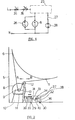
- figs. 1 and 2 show diagrammatic elevational views of two embodiments of a safety device according to the invention disposed in the rear portion of a laundry dryer, and
- figs. 3 and 4 show portions of electric circuit diagrams associated with the embodiments of figs. 1 and 2, respectively.
- With reference to fig. 1, a laundry dryer according to the invention comprises a
frame 5 and adrum 6 mounted therein for rotation about a horizontal axis and adapted to contain the laundry to be dried. The machine further comprises a blower and at least one electric heater element (not shown) for generating a flow of heated air throughdrum 6.Drum 6 is adapted to be rotated by anelectric motor 8 provided with abelt pulley 9 and mounted on asupport 10 at the lower rear portion of the frame of the machine. - In particular,
drum 6 is rotated with the aid of a conventional transmission belt 11 extendign aroundpulley 9 ofmotor 8 and arounddrum 6 and kept under tension by means of atension roll 12.Tension roll 12 is carried by alever 13 pivotally mounted at one end thereof on the frame of the machineadjacent motor 8.Tension roll 12 is continually biased into engagement with belt 11 by areturn spring 14 having its respective end anchored to lever 13 and support 10. - By properly selecting the characteristics of
return spring 14, it is tbus possible to keep belt 11 under sufficient tension for effectively transmitting the rotation ofmotor 8 todrum 6 with a minimum of wear of the belt itself. - The described laundry dryer is further provided with a safety device for preventing possible overheating and burning of the laundry in case of rupture or excessive elongation of belt 11.
- The safety device in the embodiment shown essentially comprises an
electric breaker switch 15 and an associatedslider element 16, both mounted on asupport 17adjacent motor 8 andlever 13. -
Switch 15 is provided with a spring-loadedbutton 18 cooperating with a normallyopen contact 19 connected to the electric circuitry of the machine in a manner to be described. -
Slider element 16 is adapted to slide back and forth alcna ahorizontal guide 20 ofsupport 17.Slider element 16 is connected tolever 13 by acompression spring 21 and provided with aplane surface portion 22 for actuatingbutton 18. -
Plane surface portion 22 is dimensioned such as to retainbutton 18 in its depressed state, and thus"contact 19 in its closed position, also in case of small displacements ofslider element 16 due to the action of the resilient transmission belt 11 ontension roll 12 and lever 13 during rotation ofdrum 6. - As evident from fig. 3,
contact 19 is connected in series with theprogram unit 23 of the machine, said unit being adapted to control the connection and disconnection, respectively, of the twomotors heater element 27, itself connected in series with a conventionalprotective thermostat 28. - During a normal
drying cycle contact 19 is kept closed in the manner described, permitting electric power to be simultaneously supplied tomotors heater element 27 in series withthermostat 28. - In the case of rupture of belt 11,
drum 6 stops andlever 13 is displaced in the direction of arrow A by the action ofreturn spring 14, resulting in a corresponding displacement ofslider element 16 by the action of spring 21 (fig. 1). - This results in
plane surface portion 22 ofslider element 16 releasingbutton 18, causing it to snap back to its rest position, wherebycontact 19 is permitted to open. - The open position of
contact 19 is shown in dotted lines in fig. 3. In this position,motors heater element 27 andthermostat 28 are disconnected from the electric power supply. - As a result, the flow of heated air through the drum is discontinued, and overheating or even burning of the laundry is effectively prevented.
- In a similar manner, failure of
return spring 14 results in a displacement oflever 13 in the direction of arrow B under the action of transmission belt 11. The resulting slack in transmission belt 11 arounddrum 6 results in rotation of the drum at a reduced speed or even in stoppage of the drum. - In this case,
slider element 16 is also displaced in the direction of arrow B by the action ofspring 21, wherebyplane surface portion 22 is again cause to releasebutton 18. This results inbutton 18 and dontact 19 assuming their rest positions as above descriebd, so thatmotors heater element 27 withthermostat 28 are again disconnected from the electric power supply. - Shown in fig. 2 is a laundry dryer equipped with a safety device in a second embodiment of the invention. In this figure, the above described elements of the dryer are designated by the same reference numerals as in fig. 1.
- In the second embodiment, the safety device essentially comprises two
breaker switches 29 and 30-facing each other over a short spacing and fixedly mounted in the machineadjacent motor 8 andlever 13, and aslider element 31 carried by asupport 32 secured to the machine in a positionadjacent switches - Each
breaker switch button electric contact -
Slider element 31 is adapted to slide back and froth between a pair of parallelhorizontal guides support 32, and is connected tolever 13 by acompression spring 39. -
Slider element 31 is further provided with aprojection 40 located at a position between the buttons of the two breaker switches so as to be able to selectively actuate one or the other thereof. - The dimensions of
projection 40 are selected so as to permit limited displacement ofslider element 31 under the resilient action of transmission belt 11 ontension roll 12 andlever 13 during rotation ofdrum 6 withouprojection 40 coming into contact with one of the two buttons. - As shown in fig. 4,
contacts program unit 23 of the machine, the program unit being in turn connected to the electric components of the machine in the above descriebd manner. - During normal operation of the dryer,
slider element 31 does nos act oncontacts program unit 23. - In the case of rupture of transmission belt 11 or failure of
return spring 14,slider element 31 is displaced in the direction of arrow A or B, respectively, under the action oflever 13 as described above. - As a result,
projection 40 actuates therespective button respective contact - Displacement of
slider element 31 in one or the other direction thus results in the flow of heated air through the drum being interrupted, so as to prevent overheating and burning of the laundry from occurring. - The safety device according to the invention is of a simple and reliable type and may be employed in combination with conventional safety devices protecting the machine against electric failure, resulting in a laundry dryer thus being effectively protected against any failure of its electric and mechanical components.
Claims (4)
Priority Applications (1)
| Application Number | Priority Date | Filing Date | Title |
|---|---|---|---|
| AT83111728T ATE25534T1 (en) | 1982-11-26 | 1983-11-23 | DRYER WITH SAFETY DEVICE AGAINST OVERHEATING OF THE LAUNDRY. |
Applications Claiming Priority (2)
| Application Number | Priority Date | Filing Date | Title |
|---|---|---|---|
| IT45736/82A IT1205466B (en) | 1982-11-26 | 1982-11-26 | DRYING MACHINE EQUIPPED WITH A SAFETY DEVICE AGAINST OVERHEATING OF THE LINEN |
| IT4573682 | 1982-11-26 |
Publications (2)
| Publication Number | Publication Date |
|---|---|
| EP0110318A1 true EP0110318A1 (en) | 1984-06-13 |
| EP0110318B1 EP0110318B1 (en) | 1987-02-25 |
Family
ID=11257915
Family Applications (1)
| Application Number | Title | Priority Date | Filing Date |
|---|---|---|---|
| EP83111728A Expired EP0110318B1 (en) | 1982-11-26 | 1983-11-23 | Laundry dryer with a safety device for preventing overheating of the laundry |
Country Status (4)
| Country | Link |
|---|---|
| EP (1) | EP0110318B1 (en) |
| AT (1) | ATE25534T1 (en) |
| DE (1) | DE3369863D1 (en) |
| IT (1) | IT1205466B (en) |
Cited By (8)
| Publication number | Priority date | Publication date | Assignee | Title |
|---|---|---|---|---|
| FR2578558A1 (en) * | 1985-03-05 | 1986-09-12 | Taiwan Electric Heating Equipm | Improved electrical dryer, especially for the drying of clothes |
| GB2183809A (en) * | 1985-12-06 | 1987-06-10 | Bosch Siemens Hausgeraete | Heating control in a washing machine |
| WO2004007828A1 (en) * | 2002-07-10 | 2004-01-22 | Marquardt Gmbh | Sensor for detecting belt rupture |
| WO2005064065A1 (en) * | 2003-12-23 | 2005-07-14 | BSH Bosch und Siemens Hausgeräte GmbH | Device for monitoring the drive belt of a laundry treatment machine |
| WO2008065106A1 (en) * | 2006-11-29 | 2008-06-05 | Arcelik Anonim Sirketi | A washer/dryer |
| CN101377051B (en) * | 2007-08-31 | 2012-10-31 | 海尔集团公司 | Clothes dryer belt switch structure and its working method |
| DE102007046068B4 (en) | 2006-10-02 | 2018-06-28 | Lg Electronics Inc. | Device for detecting a belt separation in a dryer and method for detecting this process |
| CN110499610A (en) * | 2018-05-18 | 2019-11-26 | 青岛海尔滚筒洗衣机有限公司 | A clutch device for clothes processing equipment |
Citations (5)
| Publication number | Priority date | Publication date | Assignee | Title |
|---|---|---|---|---|
| GB839471A (en) * | 1955-08-04 | 1960-06-29 | Gen Electric | Improvements in or relating to washing machines |
| GB885171A (en) * | 1959-04-15 | 1961-12-20 | Fisher & Paykel | Improvements in or relating to clothes driers |
| FR1404300A (en) * | 1964-08-17 | 1965-06-25 | Siemens Elektrogeraete Gmbh | Tumble dryer |
| US3890719A (en) * | 1974-01-25 | 1975-06-24 | Whirlpool Co | Broken belt power-disconnect system for dryers |
| US3890720A (en) * | 1974-01-25 | 1975-06-24 | Whirlpool Co | Broken belt switch control system for clothes dryer |
-
1982
- 1982-11-26 IT IT45736/82A patent/IT1205466B/en active
-
1983
- 1983-11-23 AT AT83111728T patent/ATE25534T1/en not_active IP Right Cessation
- 1983-11-23 DE DE8383111728T patent/DE3369863D1/en not_active Expired
- 1983-11-23 EP EP83111728A patent/EP0110318B1/en not_active Expired
Patent Citations (5)
| Publication number | Priority date | Publication date | Assignee | Title |
|---|---|---|---|---|
| GB839471A (en) * | 1955-08-04 | 1960-06-29 | Gen Electric | Improvements in or relating to washing machines |
| GB885171A (en) * | 1959-04-15 | 1961-12-20 | Fisher & Paykel | Improvements in or relating to clothes driers |
| FR1404300A (en) * | 1964-08-17 | 1965-06-25 | Siemens Elektrogeraete Gmbh | Tumble dryer |
| US3890719A (en) * | 1974-01-25 | 1975-06-24 | Whirlpool Co | Broken belt power-disconnect system for dryers |
| US3890720A (en) * | 1974-01-25 | 1975-06-24 | Whirlpool Co | Broken belt switch control system for clothes dryer |
Cited By (11)
| Publication number | Priority date | Publication date | Assignee | Title |
|---|---|---|---|---|
| FR2578558A1 (en) * | 1985-03-05 | 1986-09-12 | Taiwan Electric Heating Equipm | Improved electrical dryer, especially for the drying of clothes |
| GB2183809A (en) * | 1985-12-06 | 1987-06-10 | Bosch Siemens Hausgeraete | Heating control in a washing machine |
| GB2183809B (en) * | 1985-12-06 | 1989-10-11 | Bosch Siemens Hausgeraete | Heating control in a washing machine |
| WO2004007828A1 (en) * | 2002-07-10 | 2004-01-22 | Marquardt Gmbh | Sensor for detecting belt rupture |
| US6967297B2 (en) | 2002-07-10 | 2005-11-22 | Marquardt Gmbh | Sensor for detecting belt rupture |
| WO2005064065A1 (en) * | 2003-12-23 | 2005-07-14 | BSH Bosch und Siemens Hausgeräte GmbH | Device for monitoring the drive belt of a laundry treatment machine |
| DE102007046068B4 (en) | 2006-10-02 | 2018-06-28 | Lg Electronics Inc. | Device for detecting a belt separation in a dryer and method for detecting this process |
| WO2008065106A1 (en) * | 2006-11-29 | 2008-06-05 | Arcelik Anonim Sirketi | A washer/dryer |
| CN101377051B (en) * | 2007-08-31 | 2012-10-31 | 海尔集团公司 | Clothes dryer belt switch structure and its working method |
| CN110499610A (en) * | 2018-05-18 | 2019-11-26 | 青岛海尔滚筒洗衣机有限公司 | A clutch device for clothes processing equipment |
| CN110499610B (en) * | 2018-05-18 | 2021-12-17 | 青岛海尔洗涤电器有限公司 | Clutch device for clothes treatment equipment |
Also Published As
| Publication number | Publication date |
|---|---|
| ATE25534T1 (en) | 1987-03-15 |
| IT1205466B (en) | 1989-03-23 |
| IT8245736A0 (en) | 1982-11-26 |
| EP0110318B1 (en) | 1987-02-25 |
| DE3369863D1 (en) | 1987-04-02 |
Similar Documents
| Publication | Publication Date | Title |
|---|---|---|
| EP0110318A1 (en) | Laundry dryer with a safety device for preventing overheating of the laundry | |
| US4085303A (en) | Safety double protection device for machines having plural circuit breaker assemblies associated with doffer roller and hand guard | |
| US4488363A (en) | Combination idler and belt failure switch for a dryer | |
| US5443541A (en) | Dual element electrical clother dryer with single element interrupt circuit | |
| CA2185382C (en) | Clothes dryer temperature control system | |
| US5144516A (en) | Leakage current circuit interrupter device | |
| US7536807B2 (en) | Method and device for safe operation of a program-controlled laundry drier | |
| EP0312065B1 (en) | Safety device for a laundry drier | |
| CN101448726B (en) | Conveyor | |
| KR20010024545A (en) | Wrap detection device | |
| US4132009A (en) | Start system for domestic appliance | |
| US2734281A (en) | kauffman | |
| US20150033576A1 (en) | De-energizing electrical safety circuit | |
| GB2081074A (en) | Vacuum cleaner nozzle with a belt-driven brush roller | |
| US3325908A (en) | Dual function safety thermostat for dryers | |
| US2623979A (en) | Motor control device | |
| US4584833A (en) | Apparatus for emergency interruption of fiber supply to a spinning unit of open-end spinning machines | |
| KR100958266B1 (en) | Safety iron | |
| GB2048314A (en) | Improvements In and Relating To Electrical Machines | |
| US1714576A (en) | Electric motor control | |
| US2876556A (en) | Combined motor protector and door switch for a laundry machine | |
| SU386043A1 (en) | DUCK EDITING MACHINE | |
| JPH0454476B2 (en) | ||
| US2762900A (en) | Motor control device | |
| KR0166772B1 (en) | Arc extinguishing device for circuit breaker |
Legal Events
| Date | Code | Title | Description |
|---|---|---|---|
| PUAI | Public reference made under article 153(3) epc to a published international application that has entered the european phase |
Free format text: ORIGINAL CODE: 0009012 |
|
| AK | Designated contracting states |
Designated state(s): AT BE CH DE FR GB IT LI LU NL SE |
|
| 17P | Request for examination filed |
Effective date: 19841116 |
|
| GRAA | (expected) grant |
Free format text: ORIGINAL CODE: 0009210 |
|
| AK | Designated contracting states |
Kind code of ref document: B1 Designated state(s): AT BE CH DE FR GB IT LI LU NL SE |
|
| REF | Corresponds to: |
Ref document number: 25534 Country of ref document: AT Date of ref document: 19870315 Kind code of ref document: T |
|
| ITF | It: translation for a ep patent filed | ||
| REF | Corresponds to: |
Ref document number: 3369863 Country of ref document: DE Date of ref document: 19870402 |
|
| ET | Fr: translation filed | ||
| PLBE | No opposition filed within time limit |
Free format text: ORIGINAL CODE: 0009261 |
|
| STAA | Information on the status of an ep patent application or granted ep patent |
Free format text: STATUS: NO OPPOSITION FILED WITHIN TIME LIMIT |
|
| 26N | No opposition filed | ||
| ITPR | It: changes in ownership of a european patent |
Owner name: OFFERTA DI LICENZA AL PUBBLICO |
|
| PGFP | Annual fee paid to national office [announced via postgrant information from national office to epo] |
Ref country code: AT Payment date: 19901010 Year of fee payment: 8 |
|
| PGFP | Annual fee paid to national office [announced via postgrant information from national office to epo] |
Ref country code: CH Payment date: 19901018 Year of fee payment: 8 |
|
| PGFP | Annual fee paid to national office [announced via postgrant information from national office to epo] |
Ref country code: BE Payment date: 19901026 Year of fee payment: 8 |
|
| PGFP | Annual fee paid to national office [announced via postgrant information from national office to epo] |
Ref country code: LU Payment date: 19911108 Year of fee payment: 9 |
|
| PG25 | Lapsed in a contracting state [announced via postgrant information from national office to epo] |
Ref country code: AT Effective date: 19911123 |
|
| ITTA | It: last paid annual fee | ||
| PG25 | Lapsed in a contracting state [announced via postgrant information from national office to epo] |
Ref country code: LI Effective date: 19911130 Ref country code: CH Effective date: 19911130 Ref country code: BE Effective date: 19911130 |
|
| EPTA | Lu: last paid annual fee | ||
| BERE | Be: lapsed |
Owner name: INDUSTRIE ZANUSSI S.P.A. Effective date: 19911130 |
|
| REG | Reference to a national code |
Ref country code: CH Ref legal event code: PL |
|
| PGFP | Annual fee paid to national office [announced via postgrant information from national office to epo] |
Ref country code: FR Payment date: 19921010 Year of fee payment: 10 |
|
| PGFP | Annual fee paid to national office [announced via postgrant information from national office to epo] |
Ref country code: GB Payment date: 19921016 Year of fee payment: 10 |
|
| PGFP | Annual fee paid to national office [announced via postgrant information from national office to epo] |
Ref country code: SE Payment date: 19921019 Year of fee payment: 10 Ref country code: DE Payment date: 19921019 Year of fee payment: 10 |
|
| PG25 | Lapsed in a contracting state [announced via postgrant information from national office to epo] |
Ref country code: LU Free format text: LAPSE BECAUSE OF NON-PAYMENT OF DUE FEES Effective date: 19921123 |
|
| PGFP | Annual fee paid to national office [announced via postgrant information from national office to epo] |
Ref country code: NL Payment date: 19921130 Year of fee payment: 10 |
|
| PG25 | Lapsed in a contracting state [announced via postgrant information from national office to epo] |
Ref country code: GB Effective date: 19931123 |
|
| PG25 | Lapsed in a contracting state [announced via postgrant information from national office to epo] |
Ref country code: SE Effective date: 19931124 |
|
| PG25 | Lapsed in a contracting state [announced via postgrant information from national office to epo] |
Ref country code: NL Effective date: 19940601 |
|
| NLV4 | Nl: lapsed or anulled due to non-payment of the annual fee | ||
| GBPC | Gb: european patent ceased through non-payment of renewal fee |
Effective date: 19931123 |
|
| PG25 | Lapsed in a contracting state [announced via postgrant information from national office to epo] |
Ref country code: FR Effective date: 19940729 |
|
| PG25 | Lapsed in a contracting state [announced via postgrant information from national office to epo] |
Ref country code: DE Effective date: 19940802 |
|
| REG | Reference to a national code |
Ref country code: FR Ref legal event code: ST |
|
| EUG | Se: european patent has lapsed |
Ref document number: 83111728.8 Effective date: 19940610 |