EP0110325B1 - Durchflussmengenregelsystem - Google Patents
Durchflussmengenregelsystem Download PDFInfo
- Publication number
- EP0110325B1 EP0110325B1 EP83111739A EP83111739A EP0110325B1 EP 0110325 B1 EP0110325 B1 EP 0110325B1 EP 83111739 A EP83111739 A EP 83111739A EP 83111739 A EP83111739 A EP 83111739A EP 0110325 B1 EP0110325 B1 EP 0110325B1
- Authority
- EP
- European Patent Office
- Prior art keywords
- flow rate
- pressure
- valve
- fluid
- bypass
- Prior art date
- Legal status (The legal status is an assumption and is not a legal conclusion. Google has not performed a legal analysis and makes no representation as to the accuracy of the status listed.)
- Expired
Links
- 239000012530 fluid Substances 0.000 claims abstract description 27
- 230000001105 regulatory effect Effects 0.000 claims abstract description 17
- 230000001276 controlling effect Effects 0.000 claims description 5
- 238000011144 upstream manufacturing Methods 0.000 claims description 4
- 230000005856 abnormality Effects 0.000 claims description 3
- 239000007789 gas Substances 0.000 description 14
- 238000005259 measurement Methods 0.000 description 12
- 230000002159 abnormal effect Effects 0.000 description 7
- 238000012937 correction Methods 0.000 description 6
- 230000008859 change Effects 0.000 description 4
- YBJHBAHKTGYVGT-ZKWXMUAHSA-N (+)-Biotin Chemical compound N1C(=O)N[C@@H]2[C@H](CCCCC(=O)O)SC[C@@H]21 YBJHBAHKTGYVGT-ZKWXMUAHSA-N 0.000 description 3
- 238000006073 displacement reaction Methods 0.000 description 3
- 239000007788 liquid Substances 0.000 description 3
- 238000000034 method Methods 0.000 description 3
- FEPMHVLSLDOMQC-UHFFFAOYSA-N virginiamycin-S1 Natural products CC1OC(=O)C(C=2C=CC=CC=2)NC(=O)C2CC(=O)CCN2C(=O)C(CC=2C=CC=CC=2)N(C)C(=O)C2CCCN2C(=O)C(CC)NC(=O)C1NC(=O)C1=NC=CC=C1O FEPMHVLSLDOMQC-UHFFFAOYSA-N 0.000 description 3
- 230000006378 damage Effects 0.000 description 2
- 238000010586 diagram Methods 0.000 description 2
- 238000002474 experimental method Methods 0.000 description 2
- 230000006870 function Effects 0.000 description 2
- 230000009467 reduction Effects 0.000 description 2
- 230000004044 response Effects 0.000 description 2
- 230000001133 acceleration Effects 0.000 description 1
- 238000010276 construction Methods 0.000 description 1
- 230000008602 contraction Effects 0.000 description 1
- 230000001419 dependent effect Effects 0.000 description 1
- 230000000694 effects Effects 0.000 description 1
- 230000005484 gravity Effects 0.000 description 1
- 230000008569 process Effects 0.000 description 1
- 238000012545 processing Methods 0.000 description 1
- 230000003685 thermal hair damage Effects 0.000 description 1
Images

Classifications
-
- G—PHYSICS
- G01—MEASURING; TESTING
- G01F—MEASURING VOLUME, VOLUME FLOW, MASS FLOW OR LIQUID LEVEL; METERING BY VOLUME
- G01F1/00—Measuring the volume flow or mass flow of fluid or fluent solid material wherein the fluid passes through a meter in a continuous flow
-
- G—PHYSICS
- G05—CONTROLLING; REGULATING
- G05D—SYSTEMS FOR CONTROLLING OR REGULATING NON-ELECTRIC VARIABLES
- G05D7/00—Control of flow
- G05D7/06—Control of flow characterised by the use of electric means
- G05D7/0617—Control of flow characterised by the use of electric means specially adapted for fluid materials
- G05D7/0629—Control of flow characterised by the use of electric means specially adapted for fluid materials characterised by the type of regulator means
- G05D7/0635—Control of flow characterised by the use of electric means specially adapted for fluid materials characterised by the type of regulator means by action on throttling means
Definitions
- the present invention relates to a flow rate control system comprising the following features:
- Such a flow rate control system is disclosed in DE-B-2 654 326.
- this system comprises only a main pipe for passing therethrough the fluid to be controlled. Therefore, the quantity of the transported fluid is limited by the sectional area of the main pipe. It is not possible to control larger quantities of the fluid.
- the object of the present invention is to assure accurate flow rate control also for fluids which are transported in large quantities.
- the present invention provides a flow rate control system comprising the following features:
- the system is usable also for transporting a large quantity of fluid even if the main pipe has the orifice.
- the flow of fluid through the bypass pipe is controllable by opening or closing the bypass valve on the bypass pipe.
- the bypass valve When the bypass valve is open, the calculated flow rate is corrected according to the ratio of the cross sectional areas of the orifice and the opening of the bypass valve. So the flow rate can be controlled accurately even when the fluid is passed through the bypass pipe.
- the present embodiment includes a flow rate sensor in which an orifice is used. Stated strictly, the flow rate W (by weight) is given by the following equation.
- the equation- (1) is applied to compressible fluids such as gases and based on the assumption that the variations in density and pressure when the fluid passes through the orifice are adiabatic.
- the cross-sectional areas F and Fo, the area ratio ⁇ , g and the coefficients Cv and Cc are constants and are stored in a memory in advance as will be described below.
- the specific heat ratio X varies with the kind of gas and also with the temperature. Accordingly specific heat ratios X of various gases are predetermined by experiments at varying temperatures T, and the memory has stored therein such values as a specific heat ratio data table.
- the density y is calculated from the following equation.
- the constants Po, To, yo and K are predetermined and stored in the memory in advance.
- the density y is calculated from the equation (2) with use of the measurements of pressure P1 and temperature T.
- the compressibility factor K can be regarded as 1. If K is not 1, the compressibility factor measured as an experimental value must be stored in the memory in advance.
- the flow rate W can be calculated by measuring the primary and secondary pressures P1 and P2 and absolute temperature T.
- the flow rate of the liquid can be expressed also as a function of the primary and secondary pressures and temperature.
- the viscosity appears as a parameter instead of the specific heat ratio, and the viscosity becomes a function of the temperature.
- Fig. 1 shows the construction of a flow rate control system.
- a flow rate regulating valve 21 is mounted on a main pipe 1 for passing a gas therethrough.
- a pressure sensor 3 and a temperature sensor 4 are mounted on the main pipe 1 upstream from the valve 21.
- the pressure sensor 3 is adapted to detect pressure P1 and pressure P2 at the primary side and secondary side, respectively, of an orifice plate (not shown) provided within the main pipe 1.
- the temperature sensor 4, which is adapted to detect the temperature T of the gas flowing through the main pipe 1 comprises, for example, a thermocouple.
- the signals representing the pressures P1 and P2 and temperature T detected by these sensors 3, 4 are fed to a central processing unit (CPU) 10 via amplifier-linearizer circuits 5 and A/D converter circuits 6.
- the CPU 10 is, for example, a microprocessor.
- the main pipe 1 is provided with a bypass pipe 2 branching off the main pipe 1 upstream from the sensors 3 and 4 and joining the main pipe 1 downstream therefrom.
- a bypass valve 27 mounted on the bypass pipe 2 is opened or closed by a driver 28.
- the orifice plate At the portion of the main pipe 1 provided with the pressure sensor 3, there is the orifice plate, which therefore limits the flow rate of the gas passing through this portion.
- the bypass valve 27 is opened, permitting the gas to partly flow through the bypass 2.
- the ratio of the fluid dividedly flowing from the main pipe 1 into the bypass 2 is defined by the cross-sectional areas of the orifice of the plate in the main pipe 1 and the fully opened opening of the bypass valve 17, etc. and is approximately constant irrespective of the flow rate.
- the ratio of the rate of flow w through the bypass pipe 2 plus the rate of the remaining flow W (passing through the main pipe 1 without bypassing) to the rate of the remaining flow W (i.e. the number of times ((W+w)/W) is defined as a bypass correction factor t.
- the bypass valve 27 When the bypass valve 27 is open, the overall flow rate of the gas actually flowing is the flow rate W calculated from the equation (1) with use of the detected pressures P1 and P2 and the detected temperature T and multiplied by the correction factor t.
- the correction factor t is predetermined by experiments. When the correction factor t varies slightly with the flow rate, temperature, etc., a table thereof may be prepared in advance.
- the flow rate Ws of the fluid to be passed through the main pipe 1 (i.e., flow rate setting) is set on a device 12.
- the CPU 10 controls the degree of opening of the regulating valve 21 so that the flow rate measurement will be in match with the flow rate setting Ws.
- the regulating valve 21 can be any of needle valve, disk valve, sleeve valve, ball valve, etc. and is selected in accordance with the kind of gas to be controlled, diameter of the main pipe 1, etc.
- the member (e.g., valve stem) 22 cooperative with the valve seat (not shown) for closing the flow channel through the valve 21 is displaced by a pulse motor 23, which in turn is driven by a driver 24.
- the CPU 10 gives a shift pulse number and polarity to the driver 24.
- the shift pulse number represents the angle of rotation of the pulse motor 23, i.e., the displacement of the closing member 22, while the polarity represents the direction of rotation of the pulse motor 23, i.e., the direction of displacement of the closing member 22.
- the rotation of the pulse motor 23 is converted to a linear displacement of the closing member 22 by suitable screw-thread means or the like.
- the opening degree of the regulating valve is zero, that is, the valve is closed. If the driver 24 is continuously given the closing instruction even thereafter, the pulse motor 23 continues to rotate in the closing direction. Damage will then result, such as thermal damage to the pulse motor or biting engagement of the closing member with the valve seat.
- a pressure sensor 7 for detecting the contact pressure of the closing member 22 on the valve seat.
- the pressure sensor 7 is a strain gauge and is attached to a required portion of the closing member 22 or a member connected thereto for detecting the compressive force applied by the screw-thread means and the valve seat.
- the pressure detected is fed to a comparator circuit 9 via an amplifier circuit 8.
- the comparator circuit 9 has set therein or is given a reference value Eo, which affords the upper limit of the contact pressure between the closing member 22 and the valve seat.
- Eo the comparator circuit 9 feeds a forced stop signal to the driver 24, which deenergizes the pulse motor 23.
- the number of revolutions of the pulse motor 23 is detected by a rotation transducer 25. Accordingly the output of the transducer 25 represents the position of the closing member 22 and is shown on a display 26 as the degree of valve opening.
- the CPU has a memory (not shown) for storing the memory therefor and a memory 11 for storing various items of data.
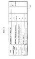
- the memory 11 has an area for storing the current measurements and preceding measurements of the pressures P1, P2 and temperature T, an area for storing the flow rate setting Ws fetched from the setting device 12, an area for storing the reference pulse number Np, abnormal variation factor Ac, high-low speed change factor S, speed reduction constant d, bypass flag F (the meanings of these will be described later) and bypass correction factor t, and an area for storing the constants and parameters required for calculating the foregoing equations (1) and (2).
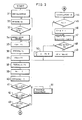
- Fig. 3 shows the control procedure to be followed by the CPU 10 for flow rate control.
- initialization is performed (step 31).
- a flow rate setting Ws is fetch to the CPU 10, which determines an opening degree corresponding to the rate Ws, and the closing member 22 opens the regulating valve 21 to the position of this opening degree.
- the valve 21 may be opened approximately to the specified position because when the fluid starts to flow, the flow rate is controlled with high accuracy by the feedback control to be described below.
- step 32 the flow rate setting Ws is fetched and compared with the value stored in the memory 11 to check whether the setting Ws was been changed (step 33). In the event of a change of the setting Ws, bypass valve control follows (step 34).
- the flow rate setting Ws is a large value to pass a large quantity of gas, there arises the need to use the bypass pipe 2.
- the flow rate setting Ws is compared with a predetermined value (which is stored in the memory 11 although not shown), and when the flow rate Ws is not smaller than the predetermined value, a valve opening instruction SB is given.
- the driver 28 opens the bypass valve 27.
- the bypass flag F is set to 1. If the flow rate setting Ws is less than the predetermined value, a valve closing instruction is given to close the bypass valve 27, and the bypass flag F is reset to 0.
- the bypass valve 27 may be opened or closed in response to some other instruction given from outside, irrespective of the setting Ws.
- step 33 When the flow rate setting Ws is fetched for the first time after the initialization, the answer to the interrogation of step 33 is always "YES" to effect bypass valve control.
- the preceding measurement P1b in the memory 11 is renewed by being replaced by the current measurement P1 (step 35).
- the primary pressure P1 is fetched and stored in the memory 11 as the current measurement (step 36).
- the preceding measurements are renewed and the current measurements are fetched (steps 37 to 40).
- the difference between the preceding primary pressure P1b and the current value P1 is calculated to check whether there was a marked pressure variation based on the difference (step 41). For one cause or another, there is the likelihood that the primary pressure will abruptly increase twofold or threefold or abruptly drop to one half or one third the preceding value.
- the abnormal variation factor Ac is so to speak a magnification of variation to provide a standard or reference for judging whether a particular variation is abnormal. For example, it is about 2. If the deviation
- the value P1b ⁇ Ac serving as a standard for the judgment is always dependent on the preceding measurement P1b according to the present embodiment, but this value may be a predetermined value.
- the flow rate W is calculated from the equations (1) and (2) with use of the current measurements P1, P2 and T and the constants and parameters stored in the memory 11 (step 44).
- the bypass flag F is checked whether it is 1 (step 45). When the flag is 0, the bypass valve 27 is held closed, with no gas flowing through the bypass pipe 2, so that the calculated flow rate W represents the rate of flow through the regulating valve 21.
- the bypass valve 27 When the bypass flag F is 1, the bypass valve 27 is open, permitting the gas to flow also through the bypass pipe 2. Accordingly the calculated flow rate W is multiplied by the bypass correction factor t to calculate the overall rate of flow (through the regulating valve 21). (Step 46). The overall flow rate are expressed by the reference character W insofar as no trouble occurs.
- the driver 24 is given a polarity signal (step 47).
- the polarity is such that the pulse motor 23 is driven in a direction to open the regulating valve 21. If otherwise, the polarity is opposite.
- step 48 the deviation IWs-W divided by Ws is checked as to whether the value is larger than the high-low speed change factor S. If the deviation
- the change factor S determines which of the two modes of control, high and low, is to be selected. It is 1 to several %.
- the reference pulse number Np multiplied by the deviation IWs-W is fed from the CPU 10 to the driver 24 as a shift pulse number (step 49).
- the reference pulse number Np is a shift pulse number to be given to the pulse motor 23 to shift the closing member 22 for the regulating valve 21 by a unit amount.
- the pulse motor 23 is driven through an angle of rotation in proportion to the deviation
- the driver 24 is given shift pulses which correspond in number to the value obtained by dividing the shift pulse number for the high speed control by the speed reduction constant d (step 50).
- the constant d is about 2 to about 3.
- step 51 follows for the treatment of trouble.
- the same treatment follows when step 42 or 43 detects an abnormal variation.
- This treatment includes assurance of the safety of the system and notifying the operator of the abnormality. The safety of the system is assured, for example, by quickly closing the regulating valve 21. (It is not always needed to fully close the valve).
- the driver 24 is given a polarity signal representing the valve closing direction and, as a shift pulse number, the reference pulse number Np multiplied by a suitable constant h (larger than 1).
- a buzzer is turned on or the display gives the information.
Landscapes
- Physics & Mathematics (AREA)
- General Physics & Mathematics (AREA)
- Engineering & Computer Science (AREA)
- Automation & Control Theory (AREA)
- Fluid Mechanics (AREA)
- Flow Control (AREA)
- Measuring Volume Flow (AREA)
Claims (4)
gekennzeichnet durch die folgenden Merkmale
Priority Applications (1)
| Application Number | Priority Date | Filing Date | Title |
|---|---|---|---|
| AT83111739T ATE36610T1 (de) | 1982-11-26 | 1983-11-24 | Durchflussmengenregelsystem. |
Applications Claiming Priority (2)
| Application Number | Priority Date | Filing Date | Title |
|---|---|---|---|
| JP57208259A JPS5998217A (ja) | 1982-11-26 | 1982-11-26 | 流量制御装置 |
| JP208259/82 | 1982-11-26 |
Publications (2)
| Publication Number | Publication Date |
|---|---|
| EP0110325A1 EP0110325A1 (de) | 1984-06-13 |
| EP0110325B1 true EP0110325B1 (de) | 1988-08-17 |
Family
ID=16553271
Family Applications (1)
| Application Number | Title | Priority Date | Filing Date |
|---|---|---|---|
| EP83111739A Expired EP0110325B1 (de) | 1982-11-26 | 1983-11-24 | Durchflussmengenregelsystem |
Country Status (6)
| Country | Link |
|---|---|
| EP (1) | EP0110325B1 (de) |
| JP (1) | JPS5998217A (de) |
| KR (1) | KR890005283B1 (de) |
| AT (1) | ATE36610T1 (de) |
| CA (1) | CA1224554A (de) |
| DE (1) | DE3377750D1 (de) |
Cited By (1)
| Publication number | Priority date | Publication date | Assignee | Title |
|---|---|---|---|---|
| US7216019B2 (en) | 2004-07-08 | 2007-05-08 | Celerity, Inc. | Method and system for a mass flow controller with reduced pressure sensitivity |
Families Citing this family (31)
| Publication number | Priority date | Publication date | Assignee | Title |
|---|---|---|---|---|
| US4527953A (en) * | 1984-10-12 | 1985-07-09 | E. I. Du Pont De Nemours And Company | Pump unit for sampling air |
| DE3526367A1 (de) | 1985-07-24 | 1986-07-03 | Daimler-Benz Ag, 7000 Stuttgart | Vorrichtung zur temperaturunabhaengigen mengenregelung von hochviskosen stoffen |
| DE3633852A1 (de) * | 1986-10-04 | 1988-04-07 | Bopp & Reuther Gmbh | Verfahren zum regeln von durchflussabhaengigen regelgroessen |
| DE3700898A1 (de) * | 1987-01-14 | 1988-07-28 | Herion Werke Kg | Mengenregelventil |
| FR2613089B1 (fr) * | 1987-03-24 | 1993-09-03 | Centre Nat Rech Scient | Procede et dispositif pour la reduction des fluctuations de debit d'un ecoulement fluide dans une canalisation |
| JPH01163712U (de) * | 1988-04-30 | 1989-11-15 | ||
| JPH02166357A (ja) * | 1988-12-19 | 1990-06-27 | Matsushita Electric Ind Co Ltd | 冷媒流量調節弁 |
| US4987933A (en) * | 1989-03-03 | 1991-01-29 | Eaton Corporation | Fluid flow control method and apparatus for minimizing particle contamination |
| US5062446A (en) * | 1991-01-07 | 1991-11-05 | Sematech, Inc. | Intelligent mass flow controller |
| DE9314741U1 (de) * | 1993-09-29 | 1994-02-24 | Fa. Hans Friedl, 83536 Gars | Flüssigkeits-Durchlaufmengenzähler |
| US6216728B1 (en) * | 1998-03-13 | 2001-04-17 | Ce Nuclear Power Llc | Tunable anticipatory output response valve control |
| US6343617B1 (en) * | 1999-07-09 | 2002-02-05 | Millipore Corporation | System and method of operation of a digital mass flow controller |
| US6539792B2 (en) | 2000-02-14 | 2003-04-01 | Unit Instruments | Method and apparatus for balancing resistance |
| KR20040024854A (ko) | 2001-04-24 | 2004-03-22 | 셀레리티 그룹 아이엔씨 | 질량유량 제어장치를 위한 시스템 및 방법 |
| JP3604354B2 (ja) * | 2001-06-13 | 2004-12-22 | Smc株式会社 | 質量流量測定方法および質量流量制御装置 |
| US6810308B2 (en) | 2002-06-24 | 2004-10-26 | Mks Instruments, Inc. | Apparatus and method for mass flow controller with network access to diagnostics |
| US7809473B2 (en) | 2002-06-24 | 2010-10-05 | Mks Instruments, Inc. | Apparatus and method for pressure fluctuation insensitive mass flow control |
| US6948508B2 (en) | 2002-06-24 | 2005-09-27 | Mks Instruments, Inc. | Apparatus and method for self-calibration of mass flow controller |
| US6712084B2 (en) | 2002-06-24 | 2004-03-30 | Mks Instruments, Inc. | Apparatus and method for pressure fluctuation insensitive mass flow control |
| US6868862B2 (en) | 2002-06-24 | 2005-03-22 | Mks Instruments, Inc. | Apparatus and method for mass flow controller with a plurality of closed loop control code sets |
| US7552015B2 (en) | 2002-06-24 | 2009-06-23 | Mks Instruments, Inc. | Apparatus and method for displaying mass flow controller pressure |
| US7004191B2 (en) | 2002-06-24 | 2006-02-28 | Mks Instruments, Inc. | Apparatus and method for mass flow controller with embedded web server |
| US7136767B2 (en) | 2002-06-24 | 2006-11-14 | Mks Instruments, Inc. | Apparatus and method for calibration of mass flow controller |
| WO2004010234A2 (en) | 2002-07-19 | 2004-01-29 | Celerity Group, Inc. | Methods and apparatus for pressure compensation in a mass flow controller |
| KR20050047079A (ko) | 2002-07-19 | 2005-05-19 | 셀레리티 그룹 아이엔씨 | 공용 기준 레그를 갖는 가변 저항기 센서 |
| US7905139B2 (en) | 2008-08-25 | 2011-03-15 | Brooks Instrument, Llc | Mass flow controller with improved dynamic |
| US8927171B2 (en) * | 2010-09-14 | 2015-01-06 | GM Global Technology Operations LLC | Method for preventing pressure in vessels from dropping below minimum allowable pressure |
| CN112492943A (zh) * | 2020-12-15 | 2021-03-16 | 塔里木大学 | 一种果园牵引式双肥箱变量施肥机及施肥方法 |
| CN113324605B (zh) * | 2021-05-26 | 2023-05-23 | 北京七星华创流量计有限公司 | 气体质量流量控制器和气体质量流量控制方法 |
| JP7224089B1 (ja) * | 2022-05-16 | 2023-02-17 | 東フロコーポレーション株式会社 | 流量制御装置 |
| WO2026077947A1 (en) | 2024-10-09 | 2026-04-16 | Actuator Solutions GmbH | Fluidic circuit with proportional valves, systems incorporating it and method for its control |
Family Cites Families (9)
| Publication number | Priority date | Publication date | Assignee | Title |
|---|---|---|---|---|
| US2949125A (en) * | 1952-11-28 | 1960-08-16 | Rockwell Mfg Co | Fluid flow system and control therefor |
| US3427442A (en) * | 1965-01-18 | 1969-02-11 | Honeywell Inc | Process control apparatus |
| US3746037A (en) * | 1971-10-06 | 1973-07-17 | Ibm | Flow control and monitoring system |
| US3845370A (en) * | 1973-08-10 | 1974-10-29 | Ibm | Credibility testing in sampled-data systems |
| CH576672A5 (de) * | 1974-04-03 | 1976-06-15 | Sulzer Ag | |
| DE2654326C2 (de) * | 1976-11-30 | 1979-02-15 | Woelk, Guenther, Prof. Dr.-Ing., 5100 Aachen | Vorrichtung zum Messen und Regeln von Mengenströmen |
| JPS5381258A (en) * | 1976-12-27 | 1978-07-18 | Sotokazu Rikuta | Method and apparatus for flow rate in byypass tube |
| US4170245A (en) * | 1978-03-03 | 1979-10-09 | Fmc Corporation | Digital control valve |
| JPS5551312A (en) * | 1978-10-11 | 1980-04-15 | Toshiba Corp | Flow quantity measuring device |
-
1982
- 1982-11-26 JP JP57208259A patent/JPS5998217A/ja active Pending
-
1983
- 1983-11-24 DE DE8383111739T patent/DE3377750D1/de not_active Expired
- 1983-11-24 AT AT83111739T patent/ATE36610T1/de not_active IP Right Cessation
- 1983-11-24 EP EP83111739A patent/EP0110325B1/de not_active Expired
- 1983-11-25 CA CA000441947A patent/CA1224554A/en not_active Expired
- 1983-11-26 KR KR1019830005605A patent/KR890005283B1/ko not_active Expired
Cited By (1)
| Publication number | Priority date | Publication date | Assignee | Title |
|---|---|---|---|---|
| US7216019B2 (en) | 2004-07-08 | 2007-05-08 | Celerity, Inc. | Method and system for a mass flow controller with reduced pressure sensitivity |
Also Published As
| Publication number | Publication date |
|---|---|
| EP0110325A1 (de) | 1984-06-13 |
| KR890005283B1 (ko) | 1989-12-20 |
| DE3377750D1 (en) | 1988-09-22 |
| JPS5998217A (ja) | 1984-06-06 |
| KR840006845A (ko) | 1984-12-03 |
| CA1224554A (en) | 1987-07-21 |
| ATE36610T1 (de) | 1988-09-15 |
Similar Documents
| Publication | Publication Date | Title |
|---|---|---|
| EP0110325A1 (de) | Durchflussmengenregelsystem | |
| TWI413880B (zh) | 用於利用多模式控制演算法來控制流體之流量的方法及設備 | |
| US5152309A (en) | Valve control apparatus | |
| EP0462432A2 (de) | Integriertes Prozess-Regelventil | |
| KR940009575A (ko) | 가스공급 설비이상 검출장치와 그 검출방법 | |
| US20190033896A1 (en) | Flow rate control apparatus, flow rate control method, and program recording medium | |
| EP3008441B1 (de) | Messsystem mit einem druckgerät sowie verfahren zur überwachung und/oder überprüfung eines solchen druckgeräts | |
| JP3546153B2 (ja) | 圧力式流量制御装置におけるオリフィス目詰検出方法およびその検出装置 | |
| JPH0769315B2 (ja) | ガスクロマトグラフ装置 | |
| WO2006060185A1 (en) | Process fluid flow device with variable orifice | |
| JPH08166309A (ja) | 導圧管の詰まり診断機構付き差圧測定装置 | |
| US5644948A (en) | Control valve with a drive operated by a pressure medium and a position controller | |
| JP2005267572A (ja) | 流量制御の異常判定方法及び装置 | |
| JPH0682282A (ja) | 流量計測装置 | |
| JPH0629796B2 (ja) | 流体抵抗式温度測定装置 | |
| JPS54104369A (en) | Flow rate measurement control apparatus | |
| JPH08178782A (ja) | 差圧測定装置 | |
| JPH0449690Y2 (de) | ||
| JPH0777488A (ja) | 摩擦力の計測装置 | |
| JPH03210608A (ja) | タンク圧力制御装置 | |
| JPH04235611A (ja) | マスフローコントローラ | |
| JPH08159825A (ja) | 流量制御系の異常検知装置 | |
| KR100527783B1 (ko) | 차량 안정성 제어 장치 및 그 방법 | |
| JP2899590B1 (ja) | 配管系に組み込まれた圧力計のドリフト検知方法 | |
| JPS6237711A (ja) | 流量制御装置 |
Legal Events
| Date | Code | Title | Description |
|---|---|---|---|
| PUAI | Public reference made under article 153(3) epc to a published international application that has entered the european phase |
Free format text: ORIGINAL CODE: 0009012 |
|
| AK | Designated contracting states |
Designated state(s): AT CH DE FR GB IT LI NL SE |
|
| 17P | Request for examination filed |
Effective date: 19840727 |
|
| 17Q | First examination report despatched |
Effective date: 19860916 |
|
| GRAA | (expected) grant |
Free format text: ORIGINAL CODE: 0009210 |
|
| AK | Designated contracting states |
Kind code of ref document: B1 Designated state(s): AT CH DE FR GB IT LI NL SE |
|
| REF | Corresponds to: |
Ref document number: 36610 Country of ref document: AT Date of ref document: 19880915 Kind code of ref document: T |
|
| REF | Corresponds to: |
Ref document number: 3377750 Country of ref document: DE Date of ref document: 19880922 |
|
| ET | Fr: translation filed | ||
| ITF | It: translation for a ep patent filed | ||
| PLBE | No opposition filed within time limit |
Free format text: ORIGINAL CODE: 0009261 |
|
| STAA | Information on the status of an ep patent application or granted ep patent |
Free format text: STATUS: NO OPPOSITION FILED WITHIN TIME LIMIT |
|
| 26N | No opposition filed | ||
| ITTA | It: last paid annual fee | ||
| EAL | Se: european patent in force in sweden |
Ref document number: 83111739.5 |
|
| REG | Reference to a national code |
Ref country code: GB Ref legal event code: IF02 |
|
| PGFP | Annual fee paid to national office [announced via postgrant information from national office to epo] |
Ref country code: DE Payment date: 20020919 Year of fee payment: 20 |
|
| PGFP | Annual fee paid to national office [announced via postgrant information from national office to epo] |
Ref country code: GB Payment date: 20021104 Year of fee payment: 20 |
|
| PGFP | Annual fee paid to national office [announced via postgrant information from national office to epo] |
Ref country code: NL Payment date: 20021118 Year of fee payment: 20 Ref country code: FR Payment date: 20021118 Year of fee payment: 20 |
|
| PGFP | Annual fee paid to national office [announced via postgrant information from national office to epo] |
Ref country code: AT Payment date: 20021119 Year of fee payment: 20 |
|
| PGFP | Annual fee paid to national office [announced via postgrant information from national office to epo] |
Ref country code: SE Payment date: 20021122 Year of fee payment: 20 Ref country code: CH Payment date: 20021122 Year of fee payment: 20 |
|
| PG25 | Lapsed in a contracting state [announced via postgrant information from national office to epo] |
Ref country code: LI Free format text: LAPSE BECAUSE OF EXPIRATION OF PROTECTION Effective date: 20031123 Ref country code: GB Free format text: LAPSE BECAUSE OF EXPIRATION OF PROTECTION Effective date: 20031123 Ref country code: CH Free format text: LAPSE BECAUSE OF EXPIRATION OF PROTECTION Effective date: 20031123 |
|
| PG25 | Lapsed in a contracting state [announced via postgrant information from national office to epo] |
Ref country code: NL Free format text: LAPSE BECAUSE OF EXPIRATION OF PROTECTION Effective date: 20031124 Ref country code: AT Free format text: LAPSE BECAUSE OF EXPIRATION OF PROTECTION Effective date: 20031124 |
|
| REG | Reference to a national code |
Ref country code: GB Ref legal event code: PE20 |
|
| REG | Reference to a national code |
Ref country code: CH Ref legal event code: PL |
|
| EUG | Se: european patent has lapsed | ||
| NLV7 | Nl: ceased due to reaching the maximum lifetime of a patent |
Effective date: 20031124 |