EP0110503A2 - Moyen de blindage électromagnétique pour un connecteur électrique - Google Patents
Moyen de blindage électromagnétique pour un connecteur électrique Download PDFInfo
- Publication number
- EP0110503A2 EP0110503A2 EP83304785A EP83304785A EP0110503A2 EP 0110503 A2 EP0110503 A2 EP 0110503A2 EP 83304785 A EP83304785 A EP 83304785A EP 83304785 A EP83304785 A EP 83304785A EP 0110503 A2 EP0110503 A2 EP 0110503A2
- Authority
- EP
- European Patent Office
- Prior art keywords
- coil spring
- electromagnetic energy
- shielding means
- spring
- connector
- Prior art date
- Legal status (The legal status is an assumption and is not a legal conclusion. Google has not performed a legal analysis and makes no representation as to the accuracy of the status listed.)
- Withdrawn
Links
- 230000013011 mating Effects 0.000 claims abstract description 11
- 229910000952 Be alloy Inorganic materials 0.000 claims 1
- 239000000853 adhesive Substances 0.000 claims 1
- 230000001070 adhesive effect Effects 0.000 claims 1
- 229910000510 noble metal Inorganic materials 0.000 claims 1
- 238000010276 construction Methods 0.000 description 5
- 230000002411 adverse Effects 0.000 description 3
- 230000000694 effects Effects 0.000 description 3
- 239000000463 material Substances 0.000 description 3
- 239000004593 Epoxy Substances 0.000 description 2
- 230000009471 action Effects 0.000 description 2
- 230000008859 change Effects 0.000 description 2
- 230000006835 compression Effects 0.000 description 2
- 238000007906 compression Methods 0.000 description 2
- 230000001965 increasing effect Effects 0.000 description 2
- 229910052751 metal Inorganic materials 0.000 description 2
- 239000002184 metal Substances 0.000 description 2
- 238000013459 approach Methods 0.000 description 1
- DMFGNRRURHSENX-UHFFFAOYSA-N beryllium copper Chemical compound [Be].[Cu] DMFGNRRURHSENX-UHFFFAOYSA-N 0.000 description 1
- 239000002131 composite material Substances 0.000 description 1
- 230000005672 electromagnetic field Effects 0.000 description 1
- 230000005670 electromagnetic radiation Effects 0.000 description 1
- PCHJSUWPFVWCPO-UHFFFAOYSA-N gold Chemical compound [Au] PCHJSUWPFVWCPO-UHFFFAOYSA-N 0.000 description 1
- 239000010931 gold Substances 0.000 description 1
- 229910052737 gold Inorganic materials 0.000 description 1
- 229910001385 heavy metal Inorganic materials 0.000 description 1
- 230000006872 improvement Effects 0.000 description 1
- 230000001939 inductive effect Effects 0.000 description 1
- 230000002452 interceptive effect Effects 0.000 description 1
- 238000002955 isolation Methods 0.000 description 1
- 238000003754 machining Methods 0.000 description 1
- 230000002093 peripheral effect Effects 0.000 description 1
- 230000002265 prevention Effects 0.000 description 1
- 230000009467 reduction Effects 0.000 description 1
- 238000003466 welding Methods 0.000 description 1
Images

Classifications
-
- H—ELECTRICITY
- H05—ELECTRIC TECHNIQUES NOT OTHERWISE PROVIDED FOR
- H05K—PRINTED CIRCUITS; CASINGS OR CONSTRUCTIONAL DETAILS OF ELECTRIC APPARATUS; MANUFACTURE OF ASSEMBLAGES OF ELECTRICAL COMPONENTS
- H05K9/00—Screening of apparatus or components against electric or magnetic fields
- H05K9/0007—Casings
- H05K9/0015—Gaskets or seals
- H05K9/0016—Gaskets or seals having a spring contact
-
- H—ELECTRICITY
- H01—ELECTRIC ELEMENTS
- H01R—ELECTRICALLY-CONDUCTIVE CONNECTIONS; STRUCTURAL ASSOCIATIONS OF A PLURALITY OF MUTUALLY-INSULATED ELECTRICAL CONNECTING ELEMENTS; COUPLING DEVICES; CURRENT COLLECTORS
- H01R13/00—Details of coupling devices of the kinds covered by groups H01R12/70 or H01R24/00 - H01R33/00
- H01R13/648—Protective earth or shield arrangements on coupling devices, e.g. anti-static shielding
- H01R13/658—High frequency shielding arrangements, e.g. against EMI [Electro-Magnetic Interference] or EMP [Electro-Magnetic Pulse]
- H01R13/6581—Shield structure
- H01R13/6582—Shield structure with resilient means for engaging mating connector
- H01R13/6583—Shield structure with resilient means for engaging mating connector with separate conductive resilient members between mating shield members
-
- H—ELECTRICITY
- H01—ELECTRIC ELEMENTS
- H01R—ELECTRICALLY-CONDUCTIVE CONNECTIONS; STRUCTURAL ASSOCIATIONS OF A PLURALITY OF MUTUALLY-INSULATED ELECTRICAL CONNECTING ELEMENTS; COUPLING DEVICES; CURRENT COLLECTORS
- H01R13/00—Details of coupling devices of the kinds covered by groups H01R12/70 or H01R24/00 - H01R33/00
- H01R13/02—Contact members
- H01R13/15—Pins, blades or sockets having separate spring member for producing or increasing contact pressure
- H01R13/187—Pins, blades or sockets having separate spring member for producing or increasing contact pressure with spring member in the socket
Definitions
- the present invention relates to an improved electromagnetic shielding means for isolating the interior of an electrical connector from external adverse electromagnetic environments.
- So-called plug and receptacle connectors include connector parts that are selectively mateable for effecting electrical connection between cable wires.
- these connectors must be capable of use in adverse environments.
- An ever increasing adverse environment encountered is that of interference from external radio frequency and electromagnetic fields frequently referred to merely as RFI and EMI.
- RFI and EMI Radio frequency and electromagnetic fields
- There have been a number of approaches attempted in the past which have been found useful in preventing such interference of relatively low frequency character and shielding devices have been used which involve relatively complex machining and spring type devices which produce electrical contact between the connector parts during mating of the plug and receptacle.
- all such known interference prevention means are not completely satisfactory in one or more respects.
- the plug part includes generally a hollow cylindrical shell member of such internal diameter as to permit its receipt onto and over a cylindrical receptacle part during mating of the connector parts.
- a groove formed circumferentially about the entire inner wall of the plug includes a continuous nelically wound spring means of special construction secured within the groove which wipes along the external wall of the receptacle as it is fitted within the plug part.
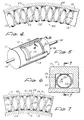
- the preferred spring means includes two helically wound, highly conductive springs which are intertwined with one another to form a single toroidal-shaped helically wound spring.
- One of the wire springs has a cross-sectional dimension less than that of the other. At crossover points between the two wire springs, they are bonded to one another.
- the large diameter helically wound part of the spring means is secured to the inner wall of the groove by use of a conductive epoxy, for example, or other means to form a good electrical connection.
- the composite toroidal-shaped spring means wipes against and is maintained in continuous contact with the outer surface of the receptacle thereby providing a good conductive path between the connector parts preventing both RFI and EMI pollution of or interference to the wires contained within the connector.
- an electrical connector of the plug and receptacle type with wnich the present invention is most advantageously employed, is identified generally as at 10.
- This connector includes a plug 11 having a metal or conductive cylindrical wall with inner and outer peripheral wall surfaces 12 and 13, respectively.
- one or more cable wires 14 interconnect in a conventional manner to electrical contacts such as the pin contact 15 that are located in the plug interior.
- the receptacle 16 which is the other half of the connector 10, includes a hollow metal cylinder of such outer diameter as to permit closely fitting receipt within the bore of the plug 11.
- one or more electrical contacts sucn as tne socket contact 17, are mounted within the receptacle 16 for mating engagement with the plug pin contact/s 15 and in that way effect electrical interconnection between cable wire 14 and a further cable wire 18.
- the plug and receptacle just described include relatively heavy metal shells surrounding the side walls as well as the end wall through which the cable wires are inserted.
- the cable wires 14 and 18 typically include a grounded shield which is connected to the connector shells. In this way, except for the open front portions of each of the connector parts, the plug and receptacle cable wires on the interior are shielded to that extent against ambient EMI and RFI interference.
- the connector parts close upon one another and only leave a small space between the receptacle outer wall and the plug inner wall surface 12 via which EMI and RFI interference can make its way to the electrical contacts and thus to electrical apparatus via tne cable wires.
- EMI and RFI interference can make its way to the electrical contacts and thus to electrical apparatus via tne cable wires.
- it is a primary function of the apparatus to be described to seal off tne space between the plug and receptacle shells when they are mated together, against the acess of electromagnetic radiation to the connector parts interior, and thereoy eliminate, or at least substantially reduce, interference from that source.
- the inner surface 12 of the plug shell 11 includes a circumferentially extending groove 19 which is rectangular in cross-section. Within the groove 19 there is located a conductive, resilient shielding means 20, to be more particulalry described, naving parts thereof which extend outwardly of the groove into the bore of the plug and effecting substantially continuous electrical connection between the plug shell and the receptacle shell 16 during mating of the two.
- the receptacle outer surface compresses the resilient shielding means 20 to effect a substantially continuous interconnection between the outer surface of the receptacle and the inner surface 12 of the plug, and in that way close off or sniela tne intervening space between the connector parts from the access of external electromagnetic energy.
- the shieldings means 20 is generally toroidal shaped and constructed of a first relatively large diameter, continuous helically wound spring 21 and a second continuous helically wound spring of lesser cross-sectional diameter 22.
- the two coil springs 21 and 22 are combined along a common toroidal axis with each cross-over point between the two coil springs being conductively secured to one another by welding, for example, as at 23.
- the cross-over points may be located at different points, it is preferred that the cross over points lie along lines, the locus of each of which is a circle centered on the axis of the connector or toroid.
- the width of diameter D of the larger spring 21 exceeds the depth dimension of the groove 19 so that when the coil means is fully seated within the groove, the inwardly directed portions of the coil spring 21 all extend outwardly of the groove and thus lie within the bore of the plug 11 ( Figure 4).
- the two springs 21 and 22 are wound or coiled in opposite directions and have the same number of turns per unit length with the coil 22 lying helically within the coil 21. That is, as is shown in Figure 4, the spring 21 is wound going from right to left in the same direction as a righthand screw motion, whereas tne spring 22 is wound in a lefthand threaded screw motion.
- the two springs fit together and provide a generally symmetrical arrangement enabling the securing of the springs together at the points 23 along two circles adjacent the sides of the groove. Moreover, this serves to equalise pressure and force distribution throughout the two coils when tne coil means 20 is compressed during use since any twisting motion of the one spring will be compensated by a twisting motion of the other spring in the opposite direction.
- crossover points may be obtained by providing that the coils have a different number of turns per unit length, whether the helixes are in the same sense or opposite sense. Also the coils may be interleaved so that one coil lies partly outside the other coil.
- the diameter of the larger spring 21 is sucn relative to the width of the groove 19 that when the plug and receptacle are mated this coil spring at most merely contacts the groove side walls. That is, on the full compression experienced during connector mating the coil spring loops are substantially entirely distended transversely. There is, of course, some change in the loop angle to the plug wall effected by the typical twisting action between the receptacle and plug as they are mated; however, securing the two counter-wound springs at 23 and providing expansion room in the groove 19 keeps the loop angle change to a mimimum.
- the shielding coil means includes two coil springs which are wound in opposite directions and interconnected to one another, electrically they form a very low inductance due to the cancelling effect of the opposing turns.
Landscapes
- Engineering & Computer Science (AREA)
- Microelectronics & Electronic Packaging (AREA)
- Details Of Connecting Devices For Male And Female Coupling (AREA)
- Coupling Device And Connection With Printed Circuit (AREA)
- Shielding Devices Or Components To Electric Or Magnetic Fields (AREA)
Applications Claiming Priority (2)
| Application Number | Priority Date | Filing Date | Title |
|---|---|---|---|
| US06/428,768 US4441780A (en) | 1982-09-30 | 1982-09-30 | Plug and receptacle electrical connector |
| US428768 | 1982-09-30 |
Publications (2)
| Publication Number | Publication Date |
|---|---|
| EP0110503A2 true EP0110503A2 (fr) | 1984-06-13 |
| EP0110503A3 EP0110503A3 (fr) | 1985-09-11 |
Family
ID=23700326
Family Applications (1)
| Application Number | Title | Priority Date | Filing Date |
|---|---|---|---|
| EP83304785A Withdrawn EP0110503A3 (fr) | 1982-09-30 | 1983-08-18 | Moyen de blindage électromagnétique pour un connecteur électrique |
Country Status (2)
| Country | Link |
|---|---|
| US (1) | US4441780A (fr) |
| EP (1) | EP0110503A3 (fr) |
Cited By (1)
| Publication number | Priority date | Publication date | Assignee | Title |
|---|---|---|---|---|
| EP0472989A1 (fr) * | 1990-08-17 | 1992-03-04 | Peter J. Balsells | Joint pour le blindage électromagnétique entre un arbre et un boîtier |
Families Citing this family (18)
| Publication number | Priority date | Publication date | Assignee | Title |
|---|---|---|---|---|
| US4614398A (en) * | 1984-12-21 | 1986-09-30 | Simmonds Precision | Shielded cable terminal connection |
| US4703133A (en) * | 1986-06-05 | 1987-10-27 | Miller John S | Electromagnetic shield |
| US4808126A (en) * | 1987-10-05 | 1989-02-28 | Itt Corporation | Electrical connector shield |
| US4934666A (en) * | 1988-04-25 | 1990-06-19 | Peter J. Balsells | Coiled spring electromagnetic shielding gasket |
| GB2231449A (en) * | 1989-04-24 | 1990-11-14 | Kern Electrical Components Lim | Electrical connector accessories for screened flat cables and circuits |
| DE3926042A1 (de) * | 1989-08-07 | 1991-02-14 | Bodo D Sperling | Elektrische-kontakt-steckverbindung |
| US5323133A (en) * | 1992-07-15 | 1994-06-21 | Lord Corporation | Method and apparatus for making electrical connection with a movable member |
| US5474309A (en) * | 1993-06-11 | 1995-12-12 | Bal Seal Engineering Company, Inc. | Gasket assembly for sealing electromagnetic waves |
| JP3195181B2 (ja) * | 1995-02-17 | 2001-08-06 | 矢崎総業株式会社 | 充電コネクタ用端子 |
| DE19528126A1 (de) * | 1995-08-01 | 1997-02-06 | Abb Patent Gmbh | Steckvorrichtung für Kabelverbindungen im Hochspannungs-Starkstrombereich |
| JP2005517275A (ja) * | 2002-02-07 | 2005-06-09 | アウト カーベル マネージメントゲゼルシャフト ミット ベシュレンクテル ハフツング | 再接触可能な接続装置 |
| US7066757B1 (en) | 2004-09-20 | 2006-06-27 | Alex Rengifo | Enveloping pin electrical contact system |
| US7429199B2 (en) * | 2005-08-12 | 2008-09-30 | Burgess James P | Low resistance, low insertion force electrical connector |
| US7502217B2 (en) * | 2007-02-16 | 2009-03-10 | Medtronic, Inc. | Filtering capacitor feedthrough assembly |
| US8593816B2 (en) | 2011-09-21 | 2013-11-26 | Medtronic, Inc. | Compact connector assembly for implantable medical device |
| US10151368B2 (en) | 2014-05-02 | 2018-12-11 | Bal Seal Engineering, Inc. | Nested canted coil springs, applications thereof, and related methods |
| DE102014211092A1 (de) * | 2014-06-11 | 2015-12-17 | Siemens Aktiengesellschaft | Elektrische Kontaktanordnung |
| CN107658601A (zh) * | 2017-10-26 | 2018-02-02 | 深圳市索诺瑞科技有限公司 | 一种超声波探头与超声成像系统的连接结构 |
Family Cites Families (5)
| Publication number | Priority date | Publication date | Assignee | Title |
|---|---|---|---|---|
| AT150912B (de) * | 1935-12-07 | 1937-10-11 | Siemens Ag | Anordnung zur federnden Verbindung von Teilen elektrischer Entladungsgefäße. |
| US3639978A (en) * | 1969-11-03 | 1972-02-08 | Atomic Energy Commission | Method for making flexible electrical connections |
| US3835443A (en) * | 1973-04-25 | 1974-09-10 | Itt | Electrical connector shield |
| US4033654A (en) * | 1976-07-29 | 1977-07-05 | Automation Industries, Inc. | Electrical connector |
| GB2057789B (en) * | 1979-08-31 | 1983-09-28 | Bendix Corp | Two part connector having electromagnetic interference protection |
-
1982
- 1982-09-30 US US06/428,768 patent/US4441780A/en not_active Expired - Fee Related
-
1983
- 1983-08-18 EP EP83304785A patent/EP0110503A3/fr not_active Withdrawn
Cited By (1)
| Publication number | Priority date | Publication date | Assignee | Title |
|---|---|---|---|---|
| EP0472989A1 (fr) * | 1990-08-17 | 1992-03-04 | Peter J. Balsells | Joint pour le blindage électromagnétique entre un arbre et un boîtier |
Also Published As
| Publication number | Publication date |
|---|---|
| EP0110503A3 (fr) | 1985-09-11 |
| US4441780A (en) | 1984-04-10 |
Similar Documents
| Publication | Publication Date | Title |
|---|---|---|
| EP0110503A2 (fr) | Moyen de blindage électromagnétique pour un connecteur électrique | |
| EP0163049B1 (fr) | Connecteur électrique blindé et méthode pour fabriquer celui-ci | |
| US3835443A (en) | Electrical connector shield | |
| CA1169533A (fr) | Blindage a couplage capacitif | |
| EP0379159B1 (fr) | Joint torique élastique pour blindage électromagnétique | |
| US4239318A (en) | Electrical connector shield | |
| CN1254880C (zh) | 平面天线 | |
| US5076797A (en) | Self-terminating coaxial plug connector for cable end installation | |
| US5074809A (en) | Ultraminiature high-frequency connection interface | |
| US4470657A (en) | Circumferential grounding and shielding spring for an electrical connector | |
| US4442438A (en) | Helical antenna structure capable of resonating at two different frequencies | |
| EP0287291A2 (fr) | Assemblage de connecteurs pour circuits intégrés à micro-ondes dans un boîtier | |
| US5618205A (en) | Wideband solderless right-angle RF interconnect | |
| US9160096B2 (en) | High speed connector | |
| US4340265A (en) | Multi-coaxial/power pin connector assembly having integral ground | |
| US3764943A (en) | Filter contact for an electrical connector | |
| EP0869584A1 (fr) | Connecteur coaxial pour la commutation d'antennes | |
| GB2229044A (en) | Coaxial line coupling device | |
| CA2260447A1 (fr) | Filtres a cavite monomodes et bimodes charges de resonateurs helicoidaux | |
| EP0774807A3 (fr) | Connecteur électrique | |
| EP0363724B1 (fr) | Connecteur pour connexion d'un circuit électrique | |
| EP1481447A1 (fr) | Ensemble connecteur pourvu d'une broche de mise a la terre laterale | |
| US5061207A (en) | Connector for a shielded coaxial cable | |
| US20220190526A1 (en) | Connector | |
| JP2900860B2 (ja) | コネクタ及びコネクタ取り付け構造 |
Legal Events
| Date | Code | Title | Description |
|---|---|---|---|
| PUAI | Public reference made under article 153(3) epc to a published international application that has entered the european phase |
Free format text: ORIGINAL CODE: 0009012 |
|
| AK | Designated contracting states |
Designated state(s): BE CH DE FR GB IT LI LU NL SE |
|
| PUAL | Search report despatched |
Free format text: ORIGINAL CODE: 0009013 |
|
| AK | Designated contracting states |
Designated state(s): BE CH DE FR GB IT LI LU NL SE |
|
| RAP1 | Party data changed (applicant data changed or rights of an application transferred) |
Owner name: G & H TECHNOLOGY, INC. |
|
| STAA | Information on the status of an ep patent application or granted ep patent |
Free format text: STATUS: THE APPLICATION IS DEEMED TO BE WITHDRAWN |
|
| 18D | Application deemed to be withdrawn |
Effective date: 19860512 |
|
| RIN1 | Information on inventor provided before grant (corrected) |
Inventor name: WALTERS, GERALD A. |