EP0110509A2 - Aufzeichnungssystem für Datenaufzeichnung auf einem Band mit einer Plattenaufzeichnungsformatierung - Google Patents
Aufzeichnungssystem für Datenaufzeichnung auf einem Band mit einer Plattenaufzeichnungsformatierung Download PDFInfo
- Publication number
- EP0110509A2 EP0110509A2 EP83305530A EP83305530A EP0110509A2 EP 0110509 A2 EP0110509 A2 EP 0110509A2 EP 83305530 A EP83305530 A EP 83305530A EP 83305530 A EP83305530 A EP 83305530A EP 0110509 A2 EP0110509 A2 EP 0110509A2
- Authority
- EP
- European Patent Office
- Prior art keywords
- segment
- transducer head
- tape
- stream
- beginning
- Prior art date
- Legal status (The legal status is an assumption and is not a legal conclusion. Google has not performed a legal analysis and makes no representation as to the accuracy of the status listed.)
- Ceased
Links
Images


Classifications
-
- G—PHYSICS
- G06—COMPUTING OR CALCULATING; COUNTING
- G06F—ELECTRIC DIGITAL DATA PROCESSING
- G06F3/00—Input arrangements for transferring data to be processed into a form capable of being handled by the computer; Output arrangements for transferring data from processing unit to output unit, e.g. interface arrangements
- G06F3/06—Digital input from, or digital output to, record carriers, e.g. RAID, emulated record carriers or networked record carriers
- G06F3/0601—Interfaces specially adapted for storage systems
-
- G—PHYSICS
- G11—INFORMATION STORAGE
- G11B—INFORMATION STORAGE BASED ON RELATIVE MOVEMENT BETWEEN RECORD CARRIER AND TRANSDUCER
- G11B15/00—Driving, starting or stopping record carriers of filamentary or web form; Driving both such record carriers and heads; Guiding such record carriers or containers therefor; Control thereof; Control of operating function
-
- G—PHYSICS
- G11—INFORMATION STORAGE
- G11B—INFORMATION STORAGE BASED ON RELATIVE MOVEMENT BETWEEN RECORD CARRIER AND TRANSDUCER
- G11B20/00—Signal processing not specific to the method of recording or reproducing; Circuits therefor
- G11B20/10—Digital recording or reproducing
- G11B20/12—Formatting, e.g. arrangement of data block or words on the record carriers
- G11B20/1262—Formatting, e.g. arrangement of data block or words on the record carriers with more than one format/standard, e.g. conversion from CD-audio format to R-DAT format
-
- G—PHYSICS
- G11—INFORMATION STORAGE
- G11B—INFORMATION STORAGE BASED ON RELATIVE MOVEMENT BETWEEN RECORD CARRIER AND TRANSDUCER
- G11B5/00—Recording by magnetisation or demagnetisation of a record carrier; Reproducing by magnetic means; Record carriers therefor
- G11B5/86—Re-recording, i.e. transcribing information from one magnetisable record carrier on to one or more similar or dissimilar record carriers
-
- G—PHYSICS
- G06—COMPUTING OR CALCULATING; COUNTING
- G06F—ELECTRIC DIGITAL DATA PROCESSING
- G06F3/00—Input arrangements for transferring data to be processed into a form capable of being handled by the computer; Output arrangements for transferring data from processing unit to output unit, e.g. interface arrangements
- G06F3/06—Digital input from, or digital output to, record carriers, e.g. RAID, emulated record carriers or networked record carriers
- G06F3/0601—Interfaces specially adapted for storage systems
- G06F3/0668—Interfaces specially adapted for storage systems adopting a particular infrastructure
- G06F3/0671—In-line storage system
- G06F3/0673—Single storage device
- G06F3/0682—Tape device
-
- G—PHYSICS
- G11—INFORMATION STORAGE
- G11B—INFORMATION STORAGE BASED ON RELATIVE MOVEMENT BETWEEN RECORD CARRIER AND TRANSDUCER
- G11B2220/00—Record carriers by type
- G11B2220/90—Tape-like record carriers
Definitions
- the present invention generally pertains to data recording systems and is particularly directed to a system for recording data on tape in a disk recording format.
- the five and one-quarter inch Winchester recording disk which provides substantial storage capacity and rapid data access is becoming increasingly popular as a principal memory for personal and small business computers, which until recently, used exclusively flexible or floppy disk memories.
- a five and one-quarter inch Winchester disk may have a memory storage capacity of, for example, fifty-five megabytes.
- a typical floppy disk may have a storage capacity of only one-quarter megabyte.
- Magnetic tape is a more practical form of backup storage for the five and one-quarter inch Winchester recording disk.
- FIG. 1 A typical prior art system for recording data on a floppy recording disk 9 is shown in Figure 1.
- This prior art system includes a disk recorder controller 10, a host interface circuit 11, a control logic circuit 12, a write logic circuit 13, a read logic circuit 14, a spindle 15, a transducer head assembly 16, a stepper motor 17, a drive motor 18, a motor driver circuit 19, a "track 00" switch 20, a write protect switch 22, an index pulse LED (light emitting diode) 23 and an index pulse detector 24.
- the disk 9 is contained in a diskette 21, and is engaged on the spindle 15 for rotation within the diskette 21.
- a CPU (central processing unit) 25 is connected to the disk recorder controller 10 by a bus 26. Data, addresses and control signals are communicated between the CPU 25 and the disk recorder controller 10 over the bus 26.
- Signals are communicated between the disk recorder controller 10 and the control logic circuit 12 via a bus 27, the host interface circuit 11 and lines 29, 30, 31, 32 and 33.
- Step command signals and a direction select signal from the disk recorder 10 are provided on lines 29 and 30 respectively to the control logic circuit 12 for controlling which track of the recording disk 9 is accessed by the transducer head.
- the recording disk 9 has concentric tracks.
- the control logic circuit 12 provides stepper A, B, C and D control signals on lines 35, 36, 37 and 38 to the stepper motor 17.
- the control logic circuit 12 provides a "track 00" signal on line 31 to the disk recorder controller 10 when the transducer head is accessed to the outermost track on the disk.
- the control logic circuit derives the "track 00" signal from line 40 which is connected to the "track 00" switch 20, together with a common line 41.
- a "motor on" signal from the disk recorder controller 10 is provided on line 33 to the control logic circuit 12 for controlling the drive motor 18.
- the drive motor 18 is coupled to the spindle 15 for rotating the turntable so that the transducer head can access various locations on each concentric track of the recording disk.
- the control logic circuit 12 provides motor drive signals on line 42 to the motor driver circuit 19, which in turn provides motor control signals on line 43 to the drive motor 18.
- a speed signal is provided on line 45 to the motor driver circuit 19 from a tachometer attached to the drive motor 18 for completing a servo loop for controlling the speed of the drive motor 18.
- the control logic circuit 12 provides a "head load solenoid" signal on line 46-to the transducer head assembly 16 for placing said transducer head in contact with the recording disk 9, thereby allowing recording on the recording disk 9.
- the control logic circuit 12 provides ; an index pulse on line 32 to the disk recorder controller 10 for every rotation of the disk 9.
- the control logic circuit 12 generates the index pulse on line 32 in response to receiving an index pulse detection signal on line 47 from the index pulse detector 24.
- the index pulse detector 24 detects light from the index pulse LED 23 that is transmitted through a hole 48 in the disk 9 at a fixed point during each rotation of the disk 9.
- the index pulse LED 23 is energized by a signal on line 49 from the control logic circuit 12.
- the format for recording on the recording disk 9 is keyed to the reception of index pulses by the disk recorder controller 10.
- the controller 10 responds to the index pulse when in a formatting mode by providing a recording signal to the write logic circuit 13 on line 51 for formatting a recorded track on the disk 9.
- the recording signal for each track includes a first fill field, followed by a predetermined number of sectors including identifying addresses and data, followed by a second fill field until the index pulse is again received upon completion of one revolution of the disk 9. Recording is enabled only when a "write gate" signal is provided by the disk recorder controller 10 to the write logic circuit on line 52.
- the write logic circuit 13 provides the signal to be recorded to the transducer head via line 53.
- a write protect switch 22 is provided for connection to a recording disk when it is desired to prevent recording on the disk 9.
- the write protect switch 22 is connected to the write logic circuit 13 by a signal line 54 and a common line 55.
- the write logic circuit 13 provides a "write protect" signal on line 57 to the disk recorder controller 10 to prevent the controller 10 from providing recording signals on write data'line 51.
- the signals on lines 51, 52 and 57 are communicated between the disk recorder controller 10 and the write logic circuit via bus 27 and the host interface circuit 11.
- the read logic circuit 14 receives signals read by the transducer head on line 59 and conditions and provides the received read data signals on line 61 to the disk recorder controller 10 via the host interface circuit 11 and bus 27.
- the present invention is a system for recording data An a stream on a recording tape in the same format that data is recorded in concentric tracks on a recording disk. That such system is a more practical form of backup storage for a hard recording disk has been pointed out above.
- a stream is one of a number of longitudinal areas on a tape defined by the accessed position of a recording head.
- One feature of the system of the present invention is that it utilizes the disk recorder controller of the prior art disk recording system described hereinabove, and thereby economically reduces development and production costs.
- the recording system of the present invention includes a read/write transducer head for reading a recording tape or recording or erasing thereon; transport apparatus for transporting the tape past the transducer head to cause the head to access a stream on the tape; a first sensor for sensing a beginning-of-stream indicator on the tape; a second sensor coupled to the transport apparatus for sensing the length of tape transported past the transducer head; a first controller coupled to the first sensor for providing an initial beginning-of-segment index pulse in response to the first sensor sensing the beginning-of-stream indicator and further coupled to the second sensor when in a formatting mode for providing end-of-segment index pulses followed by additional beginning-of-segment index pulses as a function of the length of tape transported past the transducer head following the beginning-of-segment index pulse; and a second controller coupled to the first controller for responding to each beginning-of-segment index pulse when in a formatting/ mode by providing a recording segment signal to the transducer head for
- Each recording segment includes a first fill field, followed by a predetermined number of sectors including identifying addresses and data, followed by a second fill field until a said end-of-segment index pulse is provided by the first controller.
- the segment length is equivalent to the length of a concentric track on a recording disk.
- the second controller is a prior art disk recorder controller.
- the second controller provides a write gate signal whenever a recording segment is provided to the transducer head for formatting a recorded stream on the tape.
- the first controller is coupled to the transducer head and to the second control circuit for providing an erase signal to the transducer head for erasing an inter-segment gap in the stream following provision of each end-of-segment index pulse when a write gate signal is provided simultaneously by the second controller.
- the first controller is coupled to the transducer head for providing a beginning-of-segment index pulse at the conclusion of each inter-segment gap in the formatted stream.
- the first controller is also coupled to the transducer head for providing an erase signal to the transducer head for erasing an initial gap in the stream in response to the first sensor sensing the beginning-of-stream indicator and provides the initial beginning-of-segment index pulse at the conclusion of the initial gap.
- the preferred embodiment of the system of the present invention is designed for use in the preferred embodiment of the cartridge tape drive described in a United States patent application by William M. Barton, Jr., John F. Murphy, Karl B. Offerman and Richard G. Fisher entitled “Cartridge Tape Drive", filed November.15, 1982, (attorney docket No. 2250), assigned to the same assignee as the present application, the disclosure of which prior application is incorporated herein by reference.
- the tape cartridge drive described therein is designed for receiving a magnetic tape cartridge 20 (Figure 2) similar to that described in ANSI standard X3.55-1977.
- a magnetic tape cartridge 20 ( Figure 2) similar to that described in ANSI standard X3.55-1977.
- One such cartridge is model DC300XL sold by Minnesota Mining and Manufacturing Company, Saint Paul, Minnesota, U.S.A.
- the cartridge 20 contains one-quarter inch width magnetic recording tape 44. ,
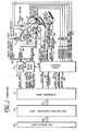
- the preferred embodiment of the recording system of the present invention is shown in Figure 2 in engagement with a tape cartridge 20.
- the system includes a capstan drive roller 56, a transducer head 62, a host controller 65, a beginning-of-stream sensing mechanism 70, a write protect sensor 76, a stepper motor 78, a transport drive motor 80, a "cartridge in place” sensor 82, a microprocessor 84, a host interface circuit 86, a read/write logic circuit 88 and a "servo and control logic” circuit 90.
- the cartridge 20 has a cut-out region 58 along one side edge thereof which is conformably shaped for receiving the transducer head 62 so that the head 62 can make contact with the tape 44 as illustrated in Figure 2.
- the cartridge 20 also has a cut-out region 64, where the capstan drive roller 56 contacts a belt capstan roller 50 within the cartridge 20.
- the belt capstan roller 50 has an upper larger portion and a lower smaller portion. The larger portion of the drive belt capstan 50 extends above and beyond the magnetic tape 44 so that the capstan drive roller 56 can engage the belt capstan roller without touching the tape 44.
- the cartridge 20 also has a mirror positioned behind a window which is utilized in connection with the beginning-of-stream sensing mechanism 70 for sensing the load point and early warning indications on the tape 44.
- the cartridge 20 also has a write protect mechanism consisting of a rotatable half cylinder positioned in front of a cut-out region. The write protect sensor 76 determines whether or not such cut-out region is blocked by the semi-circular portion of the file protect cylinder and provides a write protect signal on line 69 when the cut-out region is not blocked.
- the transducer head 62 is vertically positionable by energizing the stepper motor 78 to select any one of a plurality of different streams on the tape 44.
- the capstan drive roller 56 is mounted on the upper end of the shaft of the transport drive motor 80.
- the sensor 82 is mounted adjacent to the write protect sensor 76 and is utilized to detect when a cartridge 20 is in place within the drive.
- the host controller 65 is identical to the disk recorder controller 10 in the prior art disk recording system described above in relation to Figure 1.
- the host controller 65 communicates with the CPU 27 over the bus 26.
- the host controller 65 provides a write data signal on line 71, a write gate signal on line 73, step command signals on line 75, a direction select signal on line 77 and a "motor on" signal on line 79 in the same manner as the like- identified signals are provided by the disk recorder controller 10 on lines 51, 52, 29, 30-and 33 respectively in the prior art disk recorder system of Figure 1.
- the host controller 65 processes a read data signal received on line 81, a write protect signal received on line 83, a "track 00" signal received on line 85, and index pulses received on line 87 in the same manner as the like- identified signals received by the disk recorder control 10 from lines 61, 57, 31 and 32 respectively are processed in the prior art disk recorder system of Figure 1.
- the write data signal on line 71 from they host controller 65 is provided to the transducer head 62 via the host interface circuit 86, line 89, the read/write logic circuit 88 and line 91.
- the read data signal on line 81 is provided to the host controller 65 from the transducer head 62 via the line 91, the read/write logic circuit 88, line 93 and the host interface circuit 86.
- the write gate signal on line 73, the step command signals on line 75, the direction select signal on line 77 and the "motor on” signal on line 79 from the host controller 65 are provided to the microprocessor 84 via the host interface circuit 86 and a bus 94.
- the write protect signal on line 83, the "track 00" signal on line 85 and the index pulses on line 87 are provided to the host controller 6 5 from the microprocessor 84 via the bus 94 and the host interface circuit 86.
- the microprocessor 84 is enabled by a "cartridge in place” signal provided on line 95 from the sensor 82 when the cartridge 20 is in place in the cartridge tape drive.
- the microprocessor 84 includes logic circuits and firmware. Referring to Figure 3, the microprocessor functions as though it effectively -includes a process control logic circuit 97, an access control logic 98, an index pulse generator 99, an actual segment counter 100 and an addressed segment counter 101.
- a process flow diagram for the process control logic circuit 97 is shown in Figure 4.
- the process control logic circuit 97 responds to step commands on line 75 and the direction select signal on line 77 by providing count pulses 'on line 103 to the addressed segment counter 1101.
- the addressed segment counter 101 provides an addressed count signal on line 104 indicating the segment in the stream on the tape 44 that should be accessed by the transducer head 62.
- the actual segment counter 100 provides an actual count signal on line 105 indicating the segment being accessed by the transducer head 62.
- the process control logic circuit 97 compares the addressed count signal on line 104 with the actual count signal on line 105 and responds to such comparison by providing an access command signal on line 106 to the access control logic circuit 98 for controlling the transport apparatus in the cartridge tape drive to cause the transducer head 62 to access the segment that should be accessed.
- the operation of the actual segment counter in providing the actual count signal on line 105 is described below in relation to the description of the process flow diagram of Figure 4.
- the access control logic circuit 98 responds to the "motor on" signal on line 79 and the access command signal on line 106 by providing an access drive signal on line 107 to the "servo and control logic” circuit 90.
- the servo and control logic circuit 90 provides forward and reverse signals on lines 108 and 109 respectively to the transport drive motor 80.
- a tachometer (not shown) coupled to the capstan drive roller 56 provides a speed/distance indication signal on line 110 to the servo and control logic circuit 90 to complete a servo loop for controlling the speed at which the tape 44 is transported past the transducer head 62.
- the servo and" control logic circuit 90 fur/ther responds to the access drive signal on line 107 by providing a head position signal on line 111 to the stepper motor 78 for controlling the stepper motor 78 to cause the transducer head to access the stream on the tape 44 that contains the segment that should be accessed.
- the load point indication provided on the tape 44 as manufactured is sensed by the sensing mechanism 70 as the fully rewound tape 44 begins to be transported past the transducer head 62.
- the early warning indication provided on the tape 44 as manufactured is sensed by the sensing mechanism 70 as the fully wound tape 44 begins to be transported past the transducer head 62.
- the sensing mechanism provides a beginning-of-stream indication signal on line 112 in response to sensing the load point indication on the tape 44 when recording in the forward direction and in response to sensing the early warning indication on the tape 44 when recording in the reverse direction.
- the load point and 38 early warning indications thereby serve as beginning-of-stream indicators, and typically are provided on the tape 44 in the form of a hole 113, as in Figure 5, which illustrates a formatted stream on the tape 44. Figure 5 is not drawn to scale.
- the process control logic circuit 97 responds to the beginning-of-stream signal on line 112 by providing an erase command signal on line 114 to the read/write logic circuit' 88 to cause an erase signal to be provided ort line 115 to the transducer head 62 for erasing an initial gap 116 of a predetermined length in the stream on the tape 44.
- the process control logic circuit 97 provides an index command on line 118 to the index pulse generator 99.
- the index pulse generator 99 responds to the index command on line 118 by providing an initial beginning-of-segment index pulse on line 87 to the host controller 65.
- the host controller 65 responds to a beginning-of-segment index pulse on line 87 when in a formatting mode by providing a recording segment signal to the transducer head 62 via line 71 for formatting a recorded stream on the tape 44.
- each recorded segment 120 includes a first fill field 121, followed by a predetermined number of sectors 1, 2, ...n including identifying addresses and data, followed by a second fill field 122 until an end-of-segment index pulse is provided on line 87 by the microprocessor 84 to the host controller 65.
- the segment length is equivalent to the length of a concentric track on the recording disk 9 ( Figure 1).
- the host controller 65 also provides the write gate signal on line 73 whenever a recording segment signal is provided on line 71 to the transducer head 62 for formatting a recorded stream on the tape 44.
- the write gate signal on line 73 causes the process control logic circuit to provide a write command signal on write/erase line 114 to the read/write logic circuit 88 to enable the recording segment signal on line 71 to be provided to the transducer head 62 via line 91.
- the speed/distance indication signal on line 10 is passed by the "servo and control logic" circuit 90 via line 119 as a distance signal to the process and control logic circuit 97.
- the process and control logic circuit 97 processes the distance signal on line 119 to determine the length of tape 44 from the beginning of each segment 120.
- the process control logic circuit 97 responds to such determination by providing index commands on line 118 to the index pulse generator 99 to cause the index pulse generator 99 to generate end-of-segment index pulses on line 87 as a function of the length of tape transported past the transducer head 62 following each beginning-of-segment index pulse.
- the end-of-segment index pulses on line 87 are provided at predetermined fixed-length intervals along the stream on the tape 44 to define segments of uniform length.
- the process control logic circuit 97 provides an erase command on line 114 to the read/write logic circuit,88 for erasing an inter-segment gap 124 of a predetermined length in the stream following provision of each end-of-segment index pulse when a write gate signal is simultaneously received on line 73, thereby indicating that the host controller 65 is in a formatting mode.
- the process control logic circuit 97 provides an index command to the index pulse generator 99, which in turn provides a beginning-of-segment index pulse following each inter-segment gap 124 in the formatted stream.
- the host controller 65 responds to each beginning-of-segment index pulse on line 87 when in a formatting mode by providing a segment recording signal on line 71 as described above.
- the process control logic circuit 97 looks for a beginning-of-stream signal on line 112. If a beginning-of-stream signal is received on line 112, a command signal is provided on line 114 to cause the initial gap 116 to be erased in the stream by the transducer head 62. If a beginning-of-stream signal is not received on line 112 the process control logic circuit merely searches for a segment detection signal on line 117 which is provided upon the trailing edge of an inter-segment gap 124 being recognized by the read/write logic circuit 88 from the signal read by the transducer head 62.
- the process control logic'circuit 97 Upon either the conclusion of the erase command signal on line 114 for generating the initial gap 113, or the receipt of a segment detection signal on line 117, the process control logic'circuit 97 provides an index command signal on line 118 for causing a beginning-of-segment index pulse to be generated and provided on line 87 by the index pulse generator 99.
- the process control logic control circuit 97 Upon providing the index command signal on line 118, the process control logic control circuit 97 also provides a read enable signal on line 126 to the read/write logic circuit 88 for enabling data read by the transducer head to be provided over line 93 and thence over line 81 to the host controller 65.
- the process control logic circuit 97 determines by processing the distance signal received on line 119 whether a predetermined length of tape 44 defining a recorded segment 120 has been transported past the recording head 62, and upon each such segment-length of tape having been so transported, further determines whether a write gate signal is being received on line 73.
- the read enable signal on line 126 is discontinued so as to disable the provision of the read data signal on line 93 to the host controller via the host interface circuit 86 and line 81.
- the process control logic circuit 97 searches for a segment detection signal on line 117 which indicates that the trailing edge of an inter-segment gap 124 has been recognized.
- either the conclusion of the erase command signal on line 114 or the receipt of a segment detection signal on line 117 results in the process logic control circuit 97 providing an update count signal on line 132 to increment the count in the actual segment counter 100 by one.
- the actual segment counter 100 is reset at the beginning of each stream by a reset signal provided on line 130 by the process control logic circuit 97 in response to receipt of the beginning-of-segment signal on line 112.
- the process control logic circuit 97 provides a "track 00" signal on line 85 when the actual count signal provided on line 105 indicates that the first segment in the stream is being accessed by the transducer head 62.
- the process control logic circuit determines whether the transducer head 62 is entering the correct segment of the formatted stream as the tape is being transported in the direction in which data is recorded in the accessed stream. If so, an index command is provided on line 118 to cause the index pulse generator 99 to generate and provide another beginning-of-segment index pulse on line 87 and the process continues with the read enable signal being provided on line 126, etc.
- the process control logic circuit 97 provides an access command on line 106 to control the transport drive motor 80 to cause the transducer head to access either the beginning of the stream or the middle of the segment prior to the segment that should be accessed.
- a count update signal is then provided on line 132 to the actual segment counter 100 and the process is repeated from the start as indicated by the process flow diagram of Figure 4.
- the host controller 65 When the host controller 65 is in a read/write mode, it responds to an address requirement from the CPU 27 by searching the formatted stream accessed by the transducer head 62 for the recorded address indicated by the address signal; and the process control logic circuit 97 responds to the comparison of the count signals on lines 104 and 105 by providing an access command signal on line 106 that causes the transducer head 62 to access the segment containing the sector indicated by the address signal.
Landscapes
- Engineering & Computer Science (AREA)
- Theoretical Computer Science (AREA)
- Multimedia (AREA)
- Signal Processing (AREA)
- Human Computer Interaction (AREA)
- Physics & Mathematics (AREA)
- General Engineering & Computer Science (AREA)
- General Physics & Mathematics (AREA)
- Signal Processing For Digital Recording And Reproducing (AREA)
Applications Claiming Priority (2)
| Application Number | Priority Date | Filing Date | Title |
|---|---|---|---|
| US06/444,712 US4541019A (en) | 1982-11-26 | 1982-11-26 | Recording system for recording data on tape in a disk-recording format |
| US444712 | 1982-11-26 |
Publications (2)
| Publication Number | Publication Date |
|---|---|
| EP0110509A2 true EP0110509A2 (de) | 1984-06-13 |
| EP0110509A3 EP0110509A3 (de) | 1985-09-11 |
Family
ID=23766031
Family Applications (1)
| Application Number | Title | Priority Date | Filing Date |
|---|---|---|---|
| EP83305530A Ceased EP0110509A3 (de) | 1982-11-26 | 1983-09-20 | Aufzeichnungssystem für Datenaufzeichnung auf einem Band mit einer Plattenaufzeichnungsformatierung |
Country Status (3)
| Country | Link |
|---|---|
| US (1) | US4541019A (de) |
| EP (1) | EP0110509A3 (de) |
| JP (1) | JPS59101013A (de) |
Cited By (1)
| Publication number | Priority date | Publication date | Assignee | Title |
|---|---|---|---|---|
| US7142917B2 (en) | 2002-12-04 | 2006-11-28 | Terumo Kabushiki Kaisha | Heart treatment equipment and method for preventing fatal arrhythmia |
Families Citing this family (25)
| Publication number | Priority date | Publication date | Assignee | Title |
|---|---|---|---|---|
| US4623963A (en) | 1983-07-27 | 1986-11-18 | International Business Machines Corp. | Device independent data transfer |
| US4638383A (en) * | 1984-02-22 | 1987-01-20 | Mcginlay James G | Micro hard-disk drive system |
| US4727509A (en) * | 1984-06-28 | 1988-02-23 | Information Exchange Systems, Inc. | Master/slave system for replicating/formatting flexible magnetic diskettes |
| USRE33328E (en) * | 1985-04-17 | 1990-09-11 | Write protect control circuit for computer hard disc systems | |
| US4734851A (en) * | 1985-04-17 | 1988-03-29 | Dennis Director | Write protect control circuit for computer hard disc systems |
| US4775969A (en) * | 1986-05-15 | 1988-10-04 | Aquidneck Systems International, Inc. | Optical disk storage format, method and apparatus for emulating a magnetic tape drive |
| US5034914A (en) * | 1986-05-15 | 1991-07-23 | Aquidneck Systems International, Inc. | Optical disk data storage method and apparatus with buffered interface |
| US5247646A (en) * | 1986-05-15 | 1993-09-21 | Aquidneck Systems International, Inc. | Compressed data optical disk storage system |
| US5144501A (en) * | 1988-01-08 | 1992-09-01 | Sony Corporation | Data recorder and method of operation |
| US4858039A (en) * | 1988-02-04 | 1989-08-15 | Archive Corporation | Streaming tape drive with direct block addressability |
| US4947367A (en) * | 1988-03-28 | 1990-08-07 | Emc Corporation | System for converting digital data from magnetic tape format apparatus and method for converting a sequentially accessible magnetic tape data format to directly accessible write-once disk data format to worm optical disk format |
| JPH0782708B2 (ja) * | 1990-01-26 | 1995-09-06 | ティアツク株式会社 | データの追加書込み方法 |
| US5084787A (en) * | 1990-03-08 | 1992-01-28 | The United States Of America As Represented By The United States Department Of Energy | Method and apparatus for data decoding and processing |
| US5265208A (en) * | 1991-04-30 | 1993-11-23 | Hewlett-Packard Company | Addressable computer tape drive activation system |
| US5454098A (en) * | 1992-09-28 | 1995-09-26 | Conner Peripherals, Inc. | Method of emulating access to a sequential access data storage device while actually using a random access storage device |
| US5361176A (en) * | 1993-04-01 | 1994-11-01 | Hewlett-Packard Company | Index pulse generation in a data storage tape drive |
| US5710676A (en) * | 1996-03-12 | 1998-01-20 | International Business Machines Corporation | Pre-formatting of a storage media having fixed-size partitions |
| US6058462A (en) * | 1998-01-23 | 2000-05-02 | International Business Machines Corporation | Method and apparatus for enabling transfer of compressed data record tracks with CRC checking |
| US6778346B2 (en) * | 2000-03-30 | 2004-08-17 | Sony Corporation | Recording and reproducing apparatus and file managing method using the same |
| CN1122281C (zh) * | 2001-06-30 | 2003-09-24 | 深圳市朗科科技有限公司 | 一种多功能半导体存储装置 |
| US6988110B2 (en) * | 2003-04-23 | 2006-01-17 | International Business Machines Corporation | Storage system class distinction cues for run-time data management |
| US20050038954A1 (en) * | 2003-06-04 | 2005-02-17 | Quantum Corporation | Storage drive having universal format across media types |
| US7092185B2 (en) * | 2004-07-08 | 2006-08-15 | Agere Systems Inc. | Write gate timing for a servo bank |
| JP2006252733A (ja) * | 2005-03-14 | 2006-09-21 | Fujitsu Ltd | 媒体記憶装置及び媒体記憶装置のライト系経路診断方法。 |
| US7831793B2 (en) * | 2006-03-01 | 2010-11-09 | Quantum Corporation | Data storage system including unique block pool manager and applications in tiered storage |
Family Cites Families (6)
| Publication number | Priority date | Publication date | Assignee | Title |
|---|---|---|---|---|
| US3740720A (en) * | 1971-01-25 | 1973-06-19 | Ibm | Method adapted for continually updating information on a magnetic tape |
| BE792641A (fr) * | 1971-12-16 | 1973-03-30 | Ibm | Procede et systeme permettant d'obtenir des enregistrements magnetiquespouvant etre mis a jour |
| DE2726815A1 (de) * | 1976-06-14 | 1977-12-15 | Sharp Kk | Datensteuer- und verarbeitungsgeraet zur speicherung von digital- und tonfrequenzensignalen auf einem magnetband |
| US4321632A (en) * | 1979-06-01 | 1982-03-23 | Digital Equipment Corporation | Positioning system and formatting scheme for magnetic tape media |
| US4380047A (en) * | 1980-11-24 | 1983-04-12 | Corvus Systems, Inc. | Interface apparatus employing a video tape drive to back-up a disc drive and including error detecting and correcting circuitry |
| US4375655A (en) * | 1981-01-02 | 1983-03-01 | Memory Control Technology Corporation | Universal digital data copying system |
-
1982
- 1982-11-26 US US06/444,712 patent/US4541019A/en not_active Expired - Lifetime
-
1983
- 1983-09-20 EP EP83305530A patent/EP0110509A3/de not_active Ceased
- 1983-11-10 JP JP58210014A patent/JPS59101013A/ja active Granted
Non-Patent Citations (11)
| Title |
|---|
| COMPUTER DESIGN, vo. 21, no. 10, October 1982, pages 155-160, Winchester, Mass., US; D.M. KONRAD et al.:"Gaining compatibility through controller intelligence" * |
| COMPUTER DESIGN, vol. 21, no. 1, January 1982, pages 183-186, Winchester, Mass, US; E. SOLHJELL:"Solving the fixed disk backup dilemma" * |
| COMPUTER DESIGN, vol. 21, no. 4, April 1982, pages 103-111, Winchester, Mass. US; R. BRECHTLEIN: "An intelligent interface for disk/tape systems" * |
| ELECTRICAL DESIGN NEWS, vol. 25, no. 15, August 20, 1080, pages 133-137, Denver, US; R. GRAPPEL et al.:"Consider streaming tape for hard-disc backup" * |
| ELECTRICAL DESIGN NEWS, vol. 26, no. 6, March 18, 1981, pages 51-61, Boston, Massachusetts, US; C. WARREN:"3M-type drives' enhanced capabilities accommodate users' expanding needs" * |
| ELECTRONIC DESIGN, vol. 27, no. 22, October 25, 1979, pages 84-86, Rochelle Park, US;"Save and restore Winchester data efficiently with a streaming cartridge tape drive" * |
| ELECTRONIC DESIGN, vol. 29, no. 17, August 1981, pages 85-92, Waseca, MN, US; L. YENCHARIS: "Controllers get the most out of Winchester-to-hostinterface" * |
| ELECTRONICS INTERNATIONAL, vol. 54, no. 10, May 1981, pages 160-163, New York, US; T: SCOOROS:"Single-board controller interfaces hard disks and backup media" * |
| IBM TECHNICAL DISCLOSURE BULLETIN, vol. 20, no. 4, September 1977, pages 1359-1361, New York, US; M.J. MITCHELL Jr.:"Diskette load/dump control" * |
| IBM TECHNICAL DISCLOSURE BULLETIN, vol. 22, no. 9, February 1980, pages 4194-4195, New York, US; A. KING: "Use of a single microprocessor for DASD-tape streaming through two channels" * |
| IBM TECHNICAL DISCLOSURE BULLETIN, vol. 24, no. 4, September 1981, pages 1947-1948, New York, US; C. KINBERG et al.:"Overlapping data streaming and concurrent read/write references within a storage subsystem" * |
Cited By (1)
| Publication number | Priority date | Publication date | Assignee | Title |
|---|---|---|---|---|
| US7142917B2 (en) | 2002-12-04 | 2006-11-28 | Terumo Kabushiki Kaisha | Heart treatment equipment and method for preventing fatal arrhythmia |
Also Published As
| Publication number | Publication date |
|---|---|
| JPS59101013A (ja) | 1984-06-11 |
| US4541019A (en) | 1985-09-10 |
| JPH0461427B2 (de) | 1992-09-30 |
| EP0110509A3 (de) | 1985-09-11 |
Similar Documents
| Publication | Publication Date | Title |
|---|---|---|
| US4541019A (en) | Recording system for recording data on tape in a disk-recording format | |
| JP2798327B2 (ja) | データ処理装置を制御する方法 | |
| EP0584504B1 (de) | Bandformaterkennungssystem | |
| US5388016A (en) | Magnetic tape data management method and apparatus | |
| KR950001636A (ko) | 아이디가 없는 데이타 섹터 포맷 및 디스크 드라이브용 데이타 제어기 | |
| US4414593A (en) | Streaming cartridge tape drive | |
| US3860958A (en) | Offset read/write magnetic recording system with guard band | |
| US8054572B2 (en) | Data storage drive overwrite protection of non-worm cartridges | |
| US4563713A (en) | Method and apparatus for positioning and indexing read/write on a multiple track recording medium | |
| US4843490A (en) | System for discriminating between two tape assemblies of different recording characteristics to be loaded interchangeably in data transfer apparatus | |
| US4255807A (en) | Error testing of recording media such as magnetic tape | |
| US5268802A (en) | Reading non-standard tapes on tape drives | |
| US5155638A (en) | Compatible data storage apparatus for use with disk assemblies of two or more different storage capacities | |
| US3711844A (en) | Updatable magnetic records | |
| US5416642A (en) | Dust-immune method and apparatus for gain control of a read amplifier in a magnetic tape transport | |
| EP0595249B1 (de) | Magnetdisksteuereinrichtung, die fähig ist, fehlerhafte Schreiboperation zu vermeiden | |
| US5287229A (en) | Method of avoiding accidental overwriting on magnetic tape | |
| CA1273710C (en) | MAGNETIC TAPE SYSTEM WITH INSTRUCTION PREREADING DEVICE | |
| US7167332B2 (en) | Method and apparatus for recording data onto a recording medium including warning of the approach to an end of medium position | |
| JPH0695366B2 (ja) | ストリ−ミング磁気テ−プ装置のリポジシヨニング装置 | |
| US5436774A (en) | Dust-immune reading method and apparatus for magnetic tape transports | |
| US6057973A (en) | Method of seeking to tape segment without the use of inter-segment gap | |
| US3614020A (en) | Tape rewind speed change system | |
| CA2013183A1 (en) | Audio tape operation on a data storage drive | |
| US4791500A (en) | Method and apparatus for writing information on magnetic disk with single-gap magnetic head |
Legal Events
| Date | Code | Title | Description |
|---|---|---|---|
| PUAI | Public reference made under article 153(3) epc to a published international application that has entered the european phase |
Free format text: ORIGINAL CODE: 0009012 |
|
| AK | Designated contracting states |
Designated state(s): DE FR GB IT |
|
| PUAL | Search report despatched |
Free format text: ORIGINAL CODE: 0009013 |
|
| RHK1 | Main classification (correction) |
Ipc: G11B 20/12 |
|
| AK | Designated contracting states |
Designated state(s): DE FR GB IT |
|
| 17P | Request for examination filed |
Effective date: 19850726 |
|
| 17Q | First examination report despatched |
Effective date: 19870126 |
|
| STAA | Information on the status of an ep patent application or granted ep patent |
Free format text: STATUS: THE APPLICATION HAS BEEN REFUSED |
|
| 18R | Application refused |
Effective date: 19880925 |
|
| RIN1 | Information on inventor provided before grant (corrected) |
Inventor name: PRECOURT, NORMAND E. |