EP0110524B1 - Indicateur de panne pour pulvérisation électrostatique - Google Patents
Indicateur de panne pour pulvérisation électrostatique Download PDFInfo
- Publication number
- EP0110524B1 EP0110524B1 EP83306061A EP83306061A EP0110524B1 EP 0110524 B1 EP0110524 B1 EP 0110524B1 EP 83306061 A EP83306061 A EP 83306061A EP 83306061 A EP83306061 A EP 83306061A EP 0110524 B1 EP0110524 B1 EP 0110524B1
- Authority
- EP
- European Patent Office
- Prior art keywords
- spray
- malfunction detector
- detector system
- malfunction
- electrode
- Prior art date
- Legal status (The legal status is an assumption and is not a legal conclusion. Google has not performed a legal analysis and makes no representation as to the accuracy of the status listed.)
- Expired
Links
Images

Classifications
-
- B—PERFORMING OPERATIONS; TRANSPORTING
- B05—SPRAYING OR ATOMISING IN GENERAL; APPLYING FLUENT MATERIALS TO SURFACES, IN GENERAL
- B05B—SPRAYING APPARATUS; ATOMISING APPARATUS; NOZZLES
- B05B12/00—Arrangements for controlling delivery; Arrangements for controlling the spray area
- B05B12/004—Arrangements for controlling delivery; Arrangements for controlling the spray area comprising sensors for monitoring the delivery, e.g. by displaying the sensed value or generating an alarm
-
- B—PERFORMING OPERATIONS; TRANSPORTING
- B05—SPRAYING OR ATOMISING IN GENERAL; APPLYING FLUENT MATERIALS TO SURFACES, IN GENERAL
- B05B—SPRAYING APPARATUS; ATOMISING APPARATUS; NOZZLES
- B05B5/00—Electrostatic spraying apparatus; Spraying apparatus with means for charging the spray electrically; Apparatus for spraying liquids or other fluent materials by other electric means
- B05B5/08—Plant for applying liquids or other fluent materials to objects
- B05B5/10—Arrangements for supplying power, e.g. charging power
Definitions
- the present invention relates to spray malfunction detector systems for electrostatic sprayers and especially, but not exclusively, to such systems when used in the spraying of agricultural chemicals e.g., pesticides.
- the present invention provides a spray malfunction detector system for electrostatic spraying apparatus having a sprayhead including a nozzle connectable to a high voltage source and being adapted to direct a spray of charged particles of fluid towards an earthed target the said system comprising an earth circuit from the earthed target, an electrode located in the vicinity of the sprayhead and maintainable in use at such a potential as to attract corona discharge from the sprayhead and a current detector, characterised in that the current detector is located in the earth circuit between the earthed target and any junction in the earth circuit via which corona discharge joins the earth circuit from the said electrode.
- the said electrode is a field-intensifying electrode adapted to influence the electrostatic field in the vicinity of the sprayhead in use. Electrostatic spraying apparatus having such field-intensifying electrodes is described in our UK Patent No. 1.569.707.
- a spray malfunction detector in which a field-intensifying electrode is at least partially shrouded in electrically insulating material and in which an additional by-pass electrode is provided.
- the by-pass electrode and field-adjusting electrode are conveniently maintained at earth potential.
- the present invention permits the use of a simple current detector of a type which does not discriminate between current carried by the spray of charged particles and current due to corona discharge. In some circumstances, however; it may be advantageous to discriminate between spray current and corona discharge even when a by-pass electrode is present. These circumstances may arise when the sprayhead is heavily contaminated with plant debris causing some corona discharge to reach true earth. In this case a discriminating detector may be used.
- the current detector may be light emitter such as a neon lamp. This can conveniently be adapted to activate a photosensitive device when lit, enabling amplification in order to operate a signal, preferably audio or visual.
- an electrostatic sprayhead 1 comprises an annular channel 2 for liquid to be sprayed, between an inner core 3 and an outer wall 4 one or both being made from conducting material.
- the nozzle 12 thus formed is surrounded by, but spaced from, a field intensifying electrode in the form of a bare metal ring 5.
- the electrode 5 is connected to the earthed side of a high voltage source, comprising an HT inverter 6 and a battery 7, via junction 8.
- a trailing earth lead 9 makes electrical contact with the "true" earth 10 on which are crops to be sprayed.
- a current detector in the form a neon lamp 11.
- the whole apparatus is designed to be mounted on a frame for carrying upon the back of an operator spraying crops with agricultural chemicals.
- the sprayhead 1 is supplied with liquid from a container (not shown) and with high voltage of the order of 20 KV to produce a fine spray of charged droplets which are attracted to the crop which is at earth potential: current carried by the droplets then flows in the earth lead 9 and causes the neon lamp 11 to light giving a positive indication when spraying is taking place.
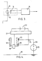
- FIG. 3 In practice in bright light a neon lamp may not be easily visible to the operator and it may be advantageous to amplify the indication from the neon lamp.
- the neon lamp 13 is located close to a photosensitive semi-conductor 14 in a black container 15.
- Light excluding potting compound is used for forming the black container and the photosensitive semi-conductor may be a photo-diode, photo-transistor or photo-resistor.
- the photosensitive semi-conductor is connected to a simple amplifier 16 the output from which may be in the form a digital yes/no output (specially useful with' tractor mounted apparatus) or may be used to activate a visual or audio indicator.
- An optional additional element is a variable resistance associated with the amplifier 16 which enables the sensitivity of the detector to be "tuned” if need be (e.g., so that it rejects both no flow and a preset low flow).
- the operator thus receives a positive indication as to whether the spray is functioning correctly, or not, even when the sprayhead itself is out of sight as is often the case with back-carried apparatus.
- the arrangement illustrated in Figure 3 has the advantage that semi-conductor components such as amplifier, digital logic etc. are opto-isolated from the HT circuit and thus rendered less vulnerable to any fluctuations, spikes etc which may occur.
- This effect can cause the current detector to register current even when no spray is being delivered.
- FIG. 4 A way of overcoming this problem according to a further aspect of the present invention is illustrated in Figure 4 in which a spray nozzle 18 is mounted within an outer housing 19 of insulating plastics material.
- a field-intensifying electrode 20 is buried in the wall of the housing so as to be fully shrouded by the insulating material from the nozzle 18 which is connected to a source of high voltage consisting of an HT generator 21 and a battery 22.
- Electrode 20 is connected to the earthed side of the high voltage source.
- a second earthed electrode 23 in the form of a bare metal ring is attached to the outside of the housing 19 about 15 to 20 cm above the electrode 20.
- Electrode 23 is connected to the earth side of the high voltage source via junction 24.
- a current detector in the form of a neon lamp 25 is located in the earth circuit 26 between "true" earth 10 and junction 24.
- by-pass electrode 23 in this example is chosen so as not to influence the operation of field-intensifying electrode 20.
- the location may be varied however provided the effect on the field in the vicinity of the nozzle is kept with acceptable limits or otherwise allowed for. Its structure and form may also be varied and multiple electrodes used if desired provided a by-pass for corona discharge is obtained.
- the complete apparatus is mounted on a tractor and in operation spraying crops with agricultural chemicals the tractor driver opens a supply of liquid (not shown) to the sprayhead 18 and connects the sprayhead to the high voltage source 21.
- a spray of fine charged droplets is formed and attracted to the crop which is at earth potential.
- a current is thus generated in the earth return circuit 26 sufficient to light neon lamp 25.
- the indication given by lamp 25 may be amplified as illustrated in Figure 3 and caused to activate an audio or visual signal in the driver's cab, thus giving a positive indication of the correct functioning of the sprayhead. if the spray ceases, stray residual current such as that caused by corona discharge will flow to electrode 23, thus bypassing the earth circuit between "true" earth 10 and junction 24 and avoiding the risk that lamp 25 may continue indicate in the absence of spray.
- the present invention therefore provides a cheap, simple and robust way of detecting spray malfunction. It responds directly to the current actually carried by the spray and reduces or eliminates interference from corona discharge thus having a greater degree of fail-safe capability and permitting the use of simple, robust devices which do not discriminate between different sources of current.
- it is possible to opto-isolate vulnerable components from the HT circuit thus safeguarding them against fluctuations or spikes in that circuit.
- the system of the present invention may also be used to detect malfunctions when spraying liquids other than agricultural chemicals e.g., paint, and with other forms of sprayhead e.g., those of linear slot configuration or spinning discs.
- agricultural chemicals e.g., paint
- other forms of sprayhead e.g., those of linear slot configuration or spinning discs.
- the apparatus When mounted on a tractor the apparatus may comprise several sprayheads mounted on a boom carried behind the tractor. In this case each sprayhead should be associated with a spray malfunction detector system if interruption of spray from individual sprayheads is to be detected.
Landscapes
- Chemical & Material Sciences (AREA)
- Analytical Chemistry (AREA)
- Electrostatic Spraying Apparatus (AREA)
- Fertilizing (AREA)
- Catching Or Destruction (AREA)
Claims (15)
Priority Applications (1)
| Application Number | Priority Date | Filing Date | Title |
|---|---|---|---|
| AT83306061T ATE31255T1 (de) | 1982-11-04 | 1983-10-06 | Stoerungsanzeiger fuer eine elektrostatische spritzvorrichtung. |
Applications Claiming Priority (4)
| Application Number | Priority Date | Filing Date | Title |
|---|---|---|---|
| GB8231486 | 1982-11-04 | ||
| GB8231486 | 1982-11-04 | ||
| GB838300770A GB8300770D0 (en) | 1983-01-12 | 1983-01-12 | Malfunction detector |
| GB8300770 | 1983-01-12 |
Publications (3)
| Publication Number | Publication Date |
|---|---|
| EP0110524A2 EP0110524A2 (fr) | 1984-06-13 |
| EP0110524A3 EP0110524A3 (en) | 1985-08-21 |
| EP0110524B1 true EP0110524B1 (fr) | 1987-12-09 |
Family
ID=26284304
Family Applications (1)
| Application Number | Title | Priority Date | Filing Date |
|---|---|---|---|
| EP83306061A Expired EP0110524B1 (fr) | 1982-11-04 | 1983-10-06 | Indicateur de panne pour pulvérisation électrostatique |
Country Status (7)
| Country | Link |
|---|---|
| US (1) | US4586657A (fr) |
| EP (1) | EP0110524B1 (fr) |
| AU (1) | AU2023883A (fr) |
| BR (1) | BR8305934A (fr) |
| CA (1) | CA1208426A (fr) |
| DE (1) | DE3374844D1 (fr) |
| GB (1) | GB2130123A (fr) |
Families Citing this family (9)
| Publication number | Priority date | Publication date | Assignee | Title |
|---|---|---|---|---|
| US4682735A (en) * | 1983-06-29 | 1987-07-28 | Graco Inc. | Electrostatic field indicator light for electrostatic nozzles |
| GB8801602D0 (en) * | 1988-01-25 | 1988-02-24 | Novatech Energy Systems | Apparatus for electrically charging liquid droplets for use in stimulation of plant growth/control of insects |
| US4986471A (en) * | 1989-07-03 | 1991-01-22 | General Dynamics Corp., Air Defense Systems Div. | Remote indicator light and safety shield for electrostatic spray gun |
| US5400975A (en) * | 1993-11-04 | 1995-03-28 | S. C. Johnson & Son, Inc. | Actuators for electrostatically charged aerosol spray systems |
| GB9409167D0 (en) * | 1994-05-09 | 1994-06-29 | Ici Plc | Spraying devices |
| US5598099A (en) * | 1995-06-22 | 1997-01-28 | Fire Sentry Systems, Inc. | System and method for coincidence detection of ungrounded parts with detectors located within and outside a production coating area |
| DE102004052949A1 (de) * | 2004-10-29 | 2006-05-04 | Nordson Corp., Westlake | Verfahren und Vorrichtung zur Überwachung von Strömungsverhältnissen in einem Leitungsstrang |
| PE20121059A1 (es) | 2010-10-07 | 2012-08-09 | Alamos Vasquez Adolfo | Nebulizadora electrostatica de alto caudal, capaz de imprimir una alta carga electrostatica en la boquilla a la gota a nebulizar, de gran simpleza de construccion |
| CN103048519B (zh) * | 2012-12-12 | 2015-01-07 | 华北电力大学 | 一种电晕初始电流的测量装置及方法 |
Family Cites Families (13)
| Publication number | Priority date | Publication date | Assignee | Title |
|---|---|---|---|---|
| US2395850A (en) * | 1943-09-18 | 1946-03-05 | Government Of The United Sates | Means for indicating the presence of radio frequency fields |
| US2610237A (en) * | 1949-11-16 | 1952-09-09 | Lloyd N Benner | Electric power indicating switch |
| US3260616A (en) * | 1961-04-06 | 1966-07-12 | George E F Brewer | Method of improving the capability of a paint composition to produce a coating of uniform appearance |
| US3831089A (en) * | 1971-08-20 | 1974-08-20 | G Pearce | Continuity tester |
| US3739228A (en) * | 1972-02-18 | 1973-06-12 | Air Ind | Apparatus for testing electrical contact between metallic objects |
| US3991367A (en) * | 1976-01-20 | 1976-11-09 | The United States Of America As Represented By The Secretary Of The Interior | Detection of potential on high-voltage transmission lines |
| GB1569707A (en) * | 1976-07-15 | 1980-06-18 | Ici Ltd | Atomisation of liquids |
| US4193356A (en) * | 1978-01-20 | 1980-03-18 | The Lely Corporation | Spray monitoring device and implement |
| ATE10711T1 (de) * | 1979-11-19 | 1984-12-15 | Imperial Chemical Industries Plc | Elektrostatischer spruehapparat. |
| GB2073052B (en) * | 1980-03-20 | 1983-12-07 | Ici Ltd | Electrostatic spraying |
| US4335419A (en) * | 1980-10-20 | 1982-06-15 | Hastings Edward E | Insulated dust control apparatus for use in an explosive environment |
| EP0058472B1 (fr) * | 1981-02-12 | 1986-04-23 | Imperial Chemical Industries Plc | Pulvérisateur agricole et réservoir à employer avec celui-ci |
| US4433296A (en) * | 1981-07-22 | 1984-02-21 | Nordson Corporation | Electrostatic system analyzer |
-
1983
- 1983-10-06 EP EP83306061A patent/EP0110524B1/fr not_active Expired
- 1983-10-06 GB GB08326784A patent/GB2130123A/en not_active Withdrawn
- 1983-10-06 DE DE8383306061T patent/DE3374844D1/de not_active Expired
- 1983-10-12 US US06/541,122 patent/US4586657A/en not_active Expired - Fee Related
- 1983-10-17 AU AU20238/83A patent/AU2023883A/en not_active Abandoned
- 1983-10-18 CA CA000439165A patent/CA1208426A/fr not_active Expired
- 1983-10-27 BR BR8305934A patent/BR8305934A/pt unknown
Also Published As
| Publication number | Publication date |
|---|---|
| EP0110524A3 (en) | 1985-08-21 |
| DE3374844D1 (en) | 1988-01-21 |
| CA1208426A (fr) | 1986-07-29 |
| BR8305934A (pt) | 1984-06-19 |
| AU2023883A (en) | 1984-05-10 |
| EP0110524A2 (fr) | 1984-06-13 |
| US4586657A (en) | 1986-05-06 |
| GB8326784D0 (en) | 1983-11-09 |
| GB2130123A (en) | 1984-05-31 |
Similar Documents
| Publication | Publication Date | Title |
|---|---|---|
| US4586657A (en) | Malfunction detector for electrostatic spraying apparatus | |
| EP0058472B1 (fr) | Pulvérisateur agricole et réservoir à employer avec celui-ci | |
| US4084748A (en) | Spray sensing system | |
| EP0198909B1 (fr) | Systeme de detection de gouttes avec element miroir | |
| EP0395135B1 (fr) | Méthode d'enregistrement et/ou d'extermination de rongeurs, par exemple des souris et des rats | |
| US5063880A (en) | Automatic spraying device for farm animals | |
| US5704554A (en) | Electrostatic spray nozzles for abrasive and conductive liquids in harsh environments | |
| US4079362A (en) | Piezo-electric seed-flow monitor | |
| EP0086030A1 (fr) | Tête de pulvérisation et installation munie d'une tête similaire | |
| US5768823A (en) | Controlled application of weed control chemicals from moving sprayer | |
| US5764145A (en) | Capacitive detector device and alarm system | |
| US3780297A (en) | Conveyor speed monitor | |
| GB2365524A (en) | Security Sensor having a Disturbance Detecting Capability | |
| CA2226502C (fr) | Buses electrostatiques pour liquides abrasifs et conducteurs | |
| GB1430891A (en) | Ionization fire sensors | |
| EP0554732A1 (fr) | Dispositif détecteur | |
| AU595292B2 (en) | Smoke detector with ionization chamber | |
| US4286424A (en) | Blockage detector for a cotton harvester | |
| JPS5998753A (ja) | 静電噴霧装置用の噴霧誤動作検出器装置 | |
| US3873981A (en) | Microwave radiation monitor | |
| US3754219A (en) | High impedance gaseous ion sensing and detection system | |
| US4788617A (en) | Liquid transfer apparatus | |
| US3399378A (en) | System for signalling between earthmoving vehicles | |
| EP0037237A2 (fr) | Circuit d'alimentation pour un ensemble de détection et d'alarme de feu du type à décharge | |
| EP0797916B1 (fr) | Méthode et dispositif pour fournir des produits à de la végétation présente sur une surface |
Legal Events
| Date | Code | Title | Description |
|---|---|---|---|
| PUAI | Public reference made under article 153(3) epc to a published international application that has entered the european phase |
Free format text: ORIGINAL CODE: 0009012 |
|
| AK | Designated contracting states |
Designated state(s): AT BE DE FR GB IT NL SE |
|
| PUAL | Search report despatched |
Free format text: ORIGINAL CODE: 0009013 |
|
| AK | Designated contracting states |
Designated state(s): AT BE DE FR GB IT NL SE |
|
| 17P | Request for examination filed |
Effective date: 19851108 |
|
| 17Q | First examination report despatched |
Effective date: 19860611 |
|
| GRAA | (expected) grant |
Free format text: ORIGINAL CODE: 0009210 |
|
| AK | Designated contracting states |
Kind code of ref document: B1 Designated state(s): AT BE DE FR GB IT NL SE |
|
| PG25 | Lapsed in a contracting state [announced via postgrant information from national office to epo] |
Ref country code: NL Effective date: 19871209 Ref country code: BE Effective date: 19871209 Ref country code: AT Effective date: 19871209 |
|
| REF | Corresponds to: |
Ref document number: 31255 Country of ref document: AT Date of ref document: 19871215 Kind code of ref document: T |
|
| ITF | It: translation for a ep patent filed | ||
| PG25 | Lapsed in a contracting state [announced via postgrant information from national office to epo] |
Ref country code: SE Effective date: 19871231 |
|
| REF | Corresponds to: |
Ref document number: 3374844 Country of ref document: DE Date of ref document: 19880121 |
|
| ET | Fr: translation filed | ||
| NLV1 | Nl: lapsed or annulled due to failure to fulfill the requirements of art. 29p and 29m of the patents act | ||
| PLBE | No opposition filed within time limit |
Free format text: ORIGINAL CODE: 0009261 |
|
| STAA | Information on the status of an ep patent application or granted ep patent |
Free format text: STATUS: NO OPPOSITION FILED WITHIN TIME LIMIT |
|
| 26N | No opposition filed | ||
| PGFP | Annual fee paid to national office [announced via postgrant information from national office to epo] |
Ref country code: GB Payment date: 19900927 Year of fee payment: 8 |
|
| PGFP | Annual fee paid to national office [announced via postgrant information from national office to epo] |
Ref country code: FR Payment date: 19910911 Year of fee payment: 9 |
|
| PGFP | Annual fee paid to national office [announced via postgrant information from national office to epo] |
Ref country code: DE Payment date: 19910930 Year of fee payment: 9 |
|
| PG25 | Lapsed in a contracting state [announced via postgrant information from national office to epo] |
Ref country code: GB Effective date: 19911006 |
|
| ITTA | It: last paid annual fee | ||
| GBPC | Gb: european patent ceased through non-payment of renewal fee | ||
| PG25 | Lapsed in a contracting state [announced via postgrant information from national office to epo] |
Ref country code: FR Effective date: 19930630 |
|
| PG25 | Lapsed in a contracting state [announced via postgrant information from national office to epo] |
Ref country code: DE Effective date: 19930701 |
|
| REG | Reference to a national code |
Ref country code: FR Ref legal event code: ST |