EP0110535A2 - Méthode et appareil pour remplacer le rouleau broyeur d'un broyeur vertical à rouleaux - Google Patents
Méthode et appareil pour remplacer le rouleau broyeur d'un broyeur vertical à rouleaux Download PDFInfo
- Publication number
- EP0110535A2 EP0110535A2 EP19830306272 EP83306272A EP0110535A2 EP 0110535 A2 EP0110535 A2 EP 0110535A2 EP 19830306272 EP19830306272 EP 19830306272 EP 83306272 A EP83306272 A EP 83306272A EP 0110535 A2 EP0110535 A2 EP 0110535A2
- Authority
- EP
- European Patent Office
- Prior art keywords
- roller
- mill
- mill housing
- cable
- grinding
- Prior art date
- Legal status (The legal status is an assumption and is not a legal conclusion. Google has not performed a legal analysis and makes no representation as to the accuracy of the status listed.)
- Withdrawn
Links
- 238000000034 method Methods 0.000 title claims description 11
- 238000005096 rolling process Methods 0.000 claims description 3
- 238000003780 insertion Methods 0.000 claims description 2
- 230000037431 insertion Effects 0.000 claims description 2
- 229910000831 Steel Inorganic materials 0.000 description 16
- 239000010959 steel Substances 0.000 description 16
- 239000000463 material Substances 0.000 description 2
- 230000003247 decreasing effect Effects 0.000 description 1
- 230000001627 detrimental effect Effects 0.000 description 1
- 239000000428 dust Substances 0.000 description 1
- 230000003014 reinforcing effect Effects 0.000 description 1
- 230000000284 resting effect Effects 0.000 description 1
- 230000000717 retained effect Effects 0.000 description 1
Images
Classifications
-
- B—PERFORMING OPERATIONS; TRANSPORTING
- B02—CRUSHING, PULVERISING, OR DISINTEGRATING; PREPARATORY TREATMENT OF GRAIN FOR MILLING
- B02C—CRUSHING, PULVERISING, OR DISINTEGRATING IN GENERAL; MILLING GRAIN
- B02C15/00—Disintegrating by milling members in the form of rollers or balls co-operating with rings or discs
-
- B—PERFORMING OPERATIONS; TRANSPORTING
- B02—CRUSHING, PULVERISING, OR DISINTEGRATING; PREPARATORY TREATMENT OF GRAIN FOR MILLING
- B02C—CRUSHING, PULVERISING, OR DISINTEGRATING IN GENERAL; MILLING GRAIN
- B02C15/00—Disintegrating by milling members in the form of rollers or balls co-operating with rings or discs
- B02C15/007—Mills with rollers pressed against a rotary horizontal disc
Definitions
- the invention relates to a method of and apparatus for replacing a grinding roller in a vertical roller.mill comprising grinding rollers rolling on a horizontal grinding table, and a mill housing having a side opening level with the rollers for removal or insertion of a grinding roller in the mill.
- a mill is hereinafter referred to as of the kind described.
- a method of replacing a roller in a mill of the kind described is characterised in that the roller to be replaced is placed in front of the side opening of the mill housing, released from its mounting and then hoisted vertically by means of at least one first cable suspended from at least one hoist at the top of the mill, whereupon a second cable suspended outside the mill and above the side opening is connected to the roller and drawn taut while the first cable is subsequently slackened and the roller thus swung out through the side opening until it only hangs on the second cable outside the mill housing, and in that a new roller is mounted in the mill by the same method.used for removing a roller, but carried out in reverse order.
- This method enables the hoist for lifting the roller to be placed in the top of the mill housing at a position which can easily be reinforced if necessary, or where the mill housing is already strong enough for carrying a grinding roller.- It is thus unnecessary to provide stiffening and reinforcing measures around the side opening in the mill housing or to dismount large parts of the mill housing and, possibly a built-in separator, for removing a roller. Furthermore, the swinging out of the grinding roller and the swinging in of a new roller can be made in a completely controlled way which is advantageous, also for reasons of security.
- the invention also includes an apparatus for carrying out the above method, characterised in that at least one hydraulic cylinder is secured to the top of the mill housing in a position substantially in the vertical centre plane of a grinding roller located in front of the side opening of the mill housing, and in that a piston rod, or an extension of the piston rod, of the cylinder extends down into the interior of the mill housing and has means for the attachment of the first cable.
- the hoisting apparatus comprises two hydraulic cylinders. which may then be disposed adjacent to the circumference of the mill housing.
- the or each cylinder is mounted on a ceiling of the mill housing in a rocker bearing so that the axis of the cylinder and the piston rod can. continuously adapt to the direction of pull in the first cable.
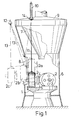
- the mill has a grinding table 1 which is rotatable about a vertical axis. Rolling on the grinding table 1 are three grinding rollers 2 which are rotatable about stationary horizontal shafts 3. The three rollers are secured to a common central frame 4 by means of flanges 5. The rollers are urged downwards against the grinding table by means of pull or pressure means, not shown.
- the mill is, in a manner known per se, encased by a mill housing 6, and at the top of the mill housing is a stationary, built-in separator 7.
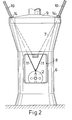
- the mill housing is provided with a side opening 8 level with the grinding rollers and having a size necessary for removing and inserting a grinding roller.
- a roof 9 of the mill housing On a roof 9 of the mill housing are mounted two hydraulic cylinders 10, the piston rods of which project into the housing.
- the cylinders are mounted in positions substantially in the centre plane of a roller placed ⁇ in front of the side opening of the housing.
- the hoisting apparatus in the form of the hydraulic cylinders, is operated in the following way:-The grinding roller to be removed from the mill housing is placed as shown in Figures 1 and 2 in front of the opening 8 of the housing. This is achieved by disconnecting the means for holding the roller axes stationary and also the means for urging the rollers downwards; and rotating the grinding table with the rollers resting and carried on the table. The grinding roller is then released from the central frame 4 and steel wires 11 fastened at one of their ends to the piston rods of the hydraulic cylinders 10 are secured at their other ends to the grinding roller 2, or as shown, form part of a continuous wire passing through a loop which is secured to the roller.
- the steel wires 11 are then effectively payed out and, by the pull from the steel wire 13 the roller is swung out through the side opening 8 from the position 2a to a position 2b in which the roller is supported by both the inside steel wire 11 and the outside steel wire 13.
- the outside steel wire 13 takes over more and more of the roller weight until the roller is suspended perpendicularly under the crane hook 12 in position 2c. In this position the steel wire 11 can be removed from the roller after which the roller can be lowered down onto a truck or carried away suspended from the crane hook 12.
Landscapes
- Engineering & Computer Science (AREA)
- Food Science & Technology (AREA)
- Crushing And Grinding (AREA)
Applications Claiming Priority (2)
| Application Number | Priority Date | Filing Date | Title |
|---|---|---|---|
| GB8233313 | 1982-11-23 | ||
| GB8233313 | 1982-11-23 |
Publications (1)
| Publication Number | Publication Date |
|---|---|
| EP0110535A2 true EP0110535A2 (fr) | 1984-06-13 |
Family
ID=10534428
Family Applications (1)
| Application Number | Title | Priority Date | Filing Date |
|---|---|---|---|
| EP19830306272 Withdrawn EP0110535A2 (fr) | 1982-11-23 | 1983-10-17 | Méthode et appareil pour remplacer le rouleau broyeur d'un broyeur vertical à rouleaux |
Country Status (1)
| Country | Link |
|---|---|
| EP (1) | EP0110535A2 (fr) |
Cited By (5)
| Publication number | Priority date | Publication date | Assignee | Title |
|---|---|---|---|---|
| DE3608192A1 (de) * | 1986-03-12 | 1987-09-17 | Pfeiffer Ag Geb | Walzenausbauvorrichtung |
| GB2449681A (en) * | 2007-05-31 | 2008-12-03 | Southwestern Corp Ltd | A method of adding additional grinding elements to a grinding mill |
| GB2451299A (en) * | 2007-10-05 | 2009-01-28 | Internat Innovative Technologi | Multi-sectional roller mill |
| CN103447789A (zh) * | 2013-05-31 | 2013-12-18 | 上海宝冶集团有限公司 | 立式磨机磨辊辊套的更换方法 |
| WO2017186971A1 (fr) * | 2016-04-29 | 2017-11-02 | General Electric Technology Gmbh | Système, procédé et appareil pour l'entretien d'un pulvérisateur |
-
1983
- 1983-10-17 EP EP19830306272 patent/EP0110535A2/fr not_active Withdrawn
Cited By (13)
| Publication number | Priority date | Publication date | Assignee | Title |
|---|---|---|---|---|
| DE3608192A1 (de) * | 1986-03-12 | 1987-09-17 | Pfeiffer Ag Geb | Walzenausbauvorrichtung |
| GB2449681A (en) * | 2007-05-31 | 2008-12-03 | Southwestern Corp Ltd | A method of adding additional grinding elements to a grinding mill |
| GB2449681B (en) * | 2007-05-31 | 2009-11-11 | Southwestern Corp Ltd | Adapting a grinding mill to introduce a grinding element |
| GB2451299A (en) * | 2007-10-05 | 2009-01-28 | Internat Innovative Technologi | Multi-sectional roller mill |
| GB2451299B (en) * | 2007-10-05 | 2009-07-22 | Internat Innovative Technologi | Multi-sectional roller mill |
| US8360351B2 (en) | 2007-10-05 | 2013-01-29 | Graham Dixon | Multi-sectional roller mill |
| CN103447789A (zh) * | 2013-05-31 | 2013-12-18 | 上海宝冶集团有限公司 | 立式磨机磨辊辊套的更换方法 |
| CN103447789B (zh) * | 2013-05-31 | 2016-08-10 | 上海宝冶集团有限公司 | 立式磨机磨辊辊套的更换方法 |
| WO2017186971A1 (fr) * | 2016-04-29 | 2017-11-02 | General Electric Technology Gmbh | Système, procédé et appareil pour l'entretien d'un pulvérisateur |
| CN109219483A (zh) * | 2016-04-29 | 2019-01-15 | 通用电器技术有限公司 | 用于保养粉碎机的系统、方法和设备 |
| KR20190041967A (ko) * | 2016-04-29 | 2019-04-23 | 제네럴 일렉트릭 테크놀러지 게엠베하 | 미분탄기를 수리하는 시스템, 방법 및 장치 |
| US10343173B2 (en) | 2016-04-29 | 2019-07-09 | General Electric Technology Gmbh | System, method and apparatus for servicing a pulverizer |
| US11679964B2 (en) | 2016-04-29 | 2023-06-20 | General Electric Technology Gmbh | System, method and apparatus for servicing a pulverizer |
Similar Documents
| Publication | Publication Date | Title |
|---|---|---|
| US8438713B2 (en) | Pin changing device and method | |
| US3973679A (en) | Bridge crane with load cells for correlating the lift operation | |
| EP0110535A2 (fr) | Méthode et appareil pour remplacer le rouleau broyeur d'un broyeur vertical à rouleaux | |
| CA2004972A1 (fr) | Mouflage a dispositif stabilisateur incorpore pour grues | |
| JP3053547B2 (ja) | 原子炉格納容器内の重量物の据付方法 | |
| CN112158585A (zh) | 物料抓取设备 | |
| CN2297432Y (zh) | 一种拆装方便的上回转塔式起重机 | |
| US4053059A (en) | Portable overhead crane and method of installing it | |
| GB2187658A (en) | Apparatus for dismounting rollers in a vertical roller mill | |
| CN211169597U (zh) | 立车随机悬臂吊 | |
| JPH08157919A (ja) | 高炉用ステーブ取付方法及び取付装置 | |
| PL189043B1 (pl) | Sposób wymiany lin nośnych w górniczych wyciągach szybowych | |
| CN210005352U (zh) | 一种建筑混凝土强度检测装置 | |
| CN207108300U (zh) | 一种单臂架固定吊 | |
| SU1022939A1 (ru) | Плавучий кран | |
| CN217323141U (zh) | 升压站导管架吊装装置 | |
| CN218452270U (zh) | 一种用于废钢破碎机喂料系统的安全防护罩 | |
| KR920007178Y1 (ko) | 제강전로 무버블후드 인출입장치 | |
| JPH0240066Y2 (fr) | ||
| CN109589523B (zh) | 臂架装置及特种车辆 | |
| CN218287841U (zh) | 一种用于煤矿机电的装载设备 | |
| CN210305478U (zh) | 一种带有防护罩的钢筋弯曲机 | |
| US20240262656A1 (en) | Elevator traction machine installation apparatus and elevator traction machine installation method | |
| SU146014A1 (ru) | Монтажный гидроподъемник | |
| KR19980043629U (ko) | 호이스팅 와이어 로프의 자동 권취장치 |
Legal Events
| Date | Code | Title | Description |
|---|---|---|---|
| PUAI | Public reference made under article 153(3) epc to a published international application that has entered the european phase |
Free format text: ORIGINAL CODE: 0009012 |
|
| AK | Designated contracting states |
Designated state(s): BE DE FR GB IT |
|
| STAA | Information on the status of an ep patent application or granted ep patent |
Free format text: STATUS: THE APPLICATION HAS BEEN WITHDRAWN |
|
| 18W | Application withdrawn |
Withdrawal date: 19841119 |
|
| RIN1 | Information on inventor provided before grant (corrected) |
Inventor name: PETERSEN, LUIS Inventor name: REINHARDT, ERIK |