EP0110604A1 - Appareil et méthode pour positionner un transducteur - Google Patents
Appareil et méthode pour positionner un transducteur Download PDFInfo
- Publication number
- EP0110604A1 EP0110604A1 EP83306891A EP83306891A EP0110604A1 EP 0110604 A1 EP0110604 A1 EP 0110604A1 EP 83306891 A EP83306891 A EP 83306891A EP 83306891 A EP83306891 A EP 83306891A EP 0110604 A1 EP0110604 A1 EP 0110604A1
- Authority
- EP
- European Patent Office
- Prior art keywords
- head
- carrier
- camming
- cam follower
- camming means
- Prior art date
- Legal status (The legal status is an assumption and is not a legal conclusion. Google has not performed a legal analysis and makes no representation as to the accuracy of the status listed.)
- Granted
Links
- 238000000034 method Methods 0.000 title claims abstract description 6
- KJFBVJALEQWJBS-XUXIUFHCSA-N maribavir Chemical compound CC(C)NC1=NC2=CC(Cl)=C(Cl)C=C2N1[C@H]1O[C@@H](CO)[C@H](O)[C@@H]1O KJFBVJALEQWJBS-XUXIUFHCSA-N 0.000 abstract 1
- 238000004519 manufacturing process Methods 0.000 description 2
- 239000000463 material Substances 0.000 description 2
- 239000003292 glue Substances 0.000 description 1
- 230000003993 interaction Effects 0.000 description 1
Images

Classifications
-
- G—PHYSICS
- G11—INFORMATION STORAGE
- G11B—INFORMATION STORAGE BASED ON RELATIVE MOVEMENT BETWEEN RECORD CARRIER AND TRANSDUCER
- G11B5/00—Recording by magnetisation or demagnetisation of a record carrier; Reproducing by magnetic means; Record carriers therefor
- G11B5/48—Disposition or mounting of heads or head supports relative to record carriers ; arrangements of heads, e.g. for scanning the record carrier to increase the relative speed
- G11B5/54—Disposition or mounting of heads or head supports relative to record carriers ; arrangements of heads, e.g. for scanning the record carrier to increase the relative speed with provision for moving the head into or out of its operative position or across tracks
- G11B5/55—Track change, selection or acquisition by displacement of the head
- G11B5/5504—Track change, selection or acquisition by displacement of the head across tape tracks
-
- G—PHYSICS
- G11—INFORMATION STORAGE
- G11B—INFORMATION STORAGE BASED ON RELATIVE MOVEMENT BETWEEN RECORD CARRIER AND TRANSDUCER
- G11B5/00—Recording by magnetisation or demagnetisation of a record carrier; Reproducing by magnetic means; Record carriers therefor
- G11B5/48—Disposition or mounting of heads or head supports relative to record carriers ; arrangements of heads, e.g. for scanning the record carrier to increase the relative speed
- G11B5/56—Disposition or mounting of heads or head supports relative to record carriers ; arrangements of heads, e.g. for scanning the record carrier to increase the relative speed with provision for moving the head support for the purpose of adjusting the position of the head relative to the record carrier, e.g. manual adjustment for azimuth correction or track centering
Definitions
- This invention relates generally to magnetic recording, and more particularly to head indexing devices for use with magnetic tape.
- the mounting, the interconnecting, and the adjustment of all these components also required a great degree of precision.
- the present invention additionally reduces the complexity of the adjustments relative to those previously required in interconnecting the individual components.
- a gear train including an electric motor and a cam, are all mounted together, as one subassembly, on a supporting member.
- One end of the supporting member is pivotably mounted to the tape machine itself, and the other end is fixed by an eccentric; as the eccentric is rotated, the end of the supporting member contacting the eccentric is moved up or down.
- the whole subassembly moves about its pivot point.
- This simple movement has the end result of adjusting the relationship of the head to the tape. This allows a relaxation in the tolerance limits in production and allows for a simple and accurate fine adjustment of the head position, relative to the tape.
- the head is adjusted, in the factory, to a given location on a reference tape. It is during this initial factory adjustment that the supporting member is pivoted. Once the head is positioned correctly, relative to the reference tape, the eccentric is fixed (e.g. by quick setting glue) and the head is then moved only by means of the electric motor and the gear train.
- the present invention is an apparatus for positioning a transducer head relative to a recording medium wherein the head is carried by a carrier mounted for translational movement and the carrier supports a cam follower means, the carrier and the cam follower means resiliently biased against a camming means, the apparatus comprising: a gear train, including both a motor and the camming means, all pivotally mounted as a single unit such that the camming means contacts the cam follower means and adjustments can be made to the position of the head relative to the medium either by pivoting the entire gear train or by rotating the camming means.
- the present invention is a method of positioning a transducer head relative to a recording medium wherein the head is carried by a carrier mounted for translational movement and the carrier supports a cam follower means, the carrier and the cam follower means resiliently biased against a camming means, whereby the rotation of the camming means to different angular positions causes the cam follower means, and consequently the head, to move, the method characterized by: pivotally mounting the camming means and the drive means therefor on a common support means; and adjusting the position of the transducer head, relative to the recording medium, by either a) moving the distal end of the common support about its pivot point, or b) rotating the camming means via the drive means.
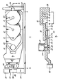
- Figure 1 depicts in simplified fashion an apparatus 10 for positioning a magnetic transducer 30 (Figure 4).
- Magnetic transducer (head) 30 is designed to read and write information on a magnetic tape.
- the movement provided to the transducer 30 is an up and down movement.
- Figures 1 and 3 be referenced together to aid in understanding the operation of the present invention.
- Figure 3 additionally depicts the gear wheels 17, 18, and 19 and motor 21 (only partly in section) with its shaft 22 and gear wheel 23.
- Apparatus 10 comprises a gear frame 12 supporting shafts 13, 14, and 15, about which gears 17, 18, and 19 respectively, rotate.
- Motor 21 ( Figure 3) is mounted to frame 12 and its shaft 22 protrudes through an aperture 24 in frame 12 and supports a gear wheel 23 for driving the gear train 26 (note: gears 23, 17, 18, and 19 are referred to collectively as gear train 26).
- Gear wheel 17 has a large diameter toothed portion referenced generally as 17a and has a smaller diameter toothed portion referenced generally as 17b.
- Gear wheel 19 includes as an integral part of itself a toothed portion 19a and a camming surface 19b (attention is directed to Figures 5a and 5b).
- Camming surface 19b interacts with cam follower 28 ( Figure 4) so as to position head carrier 29 and consequently the magnetic transducer (head) 30 itself.
- gear frame 12 is pivotally connected to the equipment housing 32 (only partially depicted) via arm 33 fitting into a recess 34 in housing 32.
- Eccentric 36 (attention is also directed to Figures 2a, 2b and 2c) comprises a disk portion 37 and a stud portion 38. Stud 38 is mounted, as shown, off-center from the center of disk 37; consequently, as disk 37 rotates about its geometric center, stud 38 follows the path of a circle. Eccentric 36 is rotated by a screwdriver or similar instrument inserted into slot 39.
- stud 38 protrudes into slot 41 provided in frame 12.
- eccentric 36 is rotated about its geometric axis stud 38 is caused to move in a generally circular motion thereby causing frame 12 to move in an up and down motion about its pivot point (i.e. arm 33).
- FIGS 2a, 2b, and 2c depict eccentric 36 in more detail.
- Eccentric 36 comprises disk portion 37 and stud portion 38.
- the geometric axis of disk portion 37 is depicted by the dashed line referenced generally as 41 (and shown simply as a point in Figure 2a).
- stud 38 follows the path of a circle.
- Figure 4 depicts gear wheel 19 and its interaction with head carrier 29 in more detail.
- the view in Figure 4 is as taken along section line 4-4 in Figure 3, omitting gear wheel 18 and additionally including head carrier 29, its associated equipment, and a section of tape 31.
- Note that the toothed portion 19a is indicated generally by three concentric broken lines.
- Head carrier 29 supports a magnetic transducer 30 and is mounted (by means not shown) so as to have only an up and down movement.
- Flanges 42a and 42b (of which only 42a can be seen in this view) support cam follower 28.
- Cam follower 28 is rotatably mounted between flanges 42a and 42b by spindle 46 and bears against camming surface 19b of gear wheel 19; spring 47 (shown schematically) exerts a force on head carrier 29 biasing it downwards toward gear wheel 19.
- gear wheel 19 is at one of its extremes of travel and head carrier 29 is consequently at its lowest position.
- Gear wheel 19 cannot move any more in a counter clockwise (CCW) direction than that shown in Figure 4 since pin 43 (protruding from gear frame 12) is contacting the end of circular slot 44 in gear wheel 19.
- Gear wheel 19 can, however, move approximately 300° in a clockwise (CW) direction until pin 43 contacts the other end of slot 44 and limits movement in that direction.
- gear wheel 19, and camming surface 19b is designed to be rotated to one of six positions, each approximately 60° apart. These six positions are the zones between the following pairs of reference characters: E and F; G and H; J and K; L and M; N and P; and R and S.
- gear 19 is in a first position with the zone between the characters E and F being at the top (12 o'clock position) and being the surface against which cam follower 28 rests.
- the second position occurs with gear wheel 19 rotated 60° C.W. from that position depicted in Figure 4, and consequently the zone between characters G and H is then at the top (12 o'clock position) and is then the surface against which cam follower 28 rests.
- the zone between characters J and K defining a third position
- the zone between characters L and M defining a fourth position
- the zone between characters N and P defining a fifth position
- the zone between characters R and S defining a sixth position.
- Figures 5a and 5b depict gear wheel 19 in somewhat more detail.
- Figure 5b is the same view as in Figure 4, and
- Figure 5a is a cross-sectional view of Figure 5b as taken along section line 5a-5a.
- camming surface 19b itself. From Figure 5b it can be seen that, beginning at letter E, and going along camming surface 19b in a counter clockwise direction, surface 19b gradually amd monotonically increases in distance from the center of shaft 15. It should be noted however, that the six zones of surface 19b referred to previously (i.e. E to F; G to H; J to K; L to M; N to P; and R to S) are each a constant distance from the center of shaft 15 for their duration i.e. they each have a constant radius for their duration. More specifically, zone E to F has a nominal radius of 0.425 inches;
- motor shaft 22 of motor 21 had an output torque of approximately 2 ounce-inches.
- Gear wheel 23 had a 0.2917 inch pitch diameter
- gear wheel 17 had a 1.1666 inch pitch diameter on its large gear 17a and a 0.2708 inch pitch diameter on its small gear 17b
- gear wheel 18 had a 1.000 inch pitch diameter
- gear wheel 19a had a 0.8125 inch pitch diameter.
- the result of this gear train was an output torque of 24 ounce-inches. It should also be noted that two revolutions of motor shaft 22 resulted in a rotation of gear wheel 19 of approximately 60°.
Landscapes
- Transmission Devices (AREA)
- Adjustment Of The Magnetic Head Position Track Following On Tapes (AREA)
Applications Claiming Priority (2)
| Application Number | Priority Date | Filing Date | Title |
|---|---|---|---|
| US06/444,868 US4566049A (en) | 1982-11-29 | 1982-11-29 | Transducer head indexing device and method |
| US444868 | 1982-11-29 |
Publications (2)
| Publication Number | Publication Date |
|---|---|
| EP0110604A1 true EP0110604A1 (fr) | 1984-06-13 |
| EP0110604B1 EP0110604B1 (fr) | 1987-02-04 |
Family
ID=23766679
Family Applications (1)
| Application Number | Title | Priority Date | Filing Date |
|---|---|---|---|
| EP83306891A Expired EP0110604B1 (fr) | 1982-11-29 | 1983-11-11 | Appareil et méthode pour positionner un transducteur |
Country Status (5)
| Country | Link |
|---|---|
| US (1) | US4566049A (fr) |
| EP (1) | EP0110604B1 (fr) |
| JP (1) | JPS59110025A (fr) |
| CA (1) | CA1197007A (fr) |
| DE (1) | DE3369761D1 (fr) |
Cited By (1)
| Publication number | Priority date | Publication date | Assignee | Title |
|---|---|---|---|---|
| EP0235643B1 (fr) * | 1986-02-14 | 1991-01-02 | Hewlett-Packard Company | Contrôle d'arrêt limite pour un entraînement de disque à mémoire |
Families Citing this family (2)
| Publication number | Priority date | Publication date | Assignee | Title |
|---|---|---|---|---|
| JPS609066U (ja) * | 1983-06-29 | 1985-01-22 | アルプス電気株式会社 | ヘツドのトラツク位置調整装置 |
| DE69626812T2 (de) * | 1996-09-13 | 2003-10-02 | Deutsche Thomson-Brandt Gmbh | Vorrichtung für Grob- und Feinpositionierung eines ersten und zweiten Elementes relativ zueinander |
Citations (4)
| Publication number | Priority date | Publication date | Assignee | Title |
|---|---|---|---|---|
| US4003092A (en) * | 1973-11-15 | 1977-01-11 | Canon Kabushiki Kaisha | Reading or writing head positioning device |
| GB1474953A (en) * | 1973-07-12 | 1977-05-25 | Basf Ag | Recording/playback transducer positioning and adjusting device |
| US4144549A (en) * | 1977-11-21 | 1979-03-13 | Basf Aktiengesellschaft | Transducer positioning device |
| EP0003339A1 (fr) * | 1978-01-23 | 1979-08-08 | BASF Aktiengesellschaft | Dispositif pour positionner avec précision une tête transductrice dans des systèmes d'enregistrement |
Family Cites Families (5)
| Publication number | Priority date | Publication date | Assignee | Title |
|---|---|---|---|---|
| US3661397A (en) * | 1969-07-25 | 1972-05-09 | Eg & G Inc | Addressing mechanism |
| US3761644A (en) * | 1970-04-21 | 1973-09-25 | Iit Res Inst | Mounting structure for transducer heads |
| US3833923A (en) * | 1972-08-21 | 1974-09-03 | Iit | Channel indexing system with manual or automatic operation and with manual fine adjustment |
| US3839735A (en) * | 1972-10-13 | 1974-10-01 | Newell Ind | Transducer head positioning device |
| DE2918020A1 (de) * | 1979-05-04 | 1980-11-13 | Basf Ag | Positioniereinrichtung fuer einen magnetkopf eines magnetbandgeraetes |
-
1982
- 1982-11-29 US US06/444,868 patent/US4566049A/en not_active Expired - Lifetime
-
1983
- 1983-03-03 CA CA000422800A patent/CA1197007A/fr not_active Expired
- 1983-11-11 DE DE8383306891T patent/DE3369761D1/de not_active Expired
- 1983-11-11 EP EP83306891A patent/EP0110604B1/fr not_active Expired
- 1983-11-28 JP JP58222289A patent/JPS59110025A/ja active Pending
Patent Citations (4)
| Publication number | Priority date | Publication date | Assignee | Title |
|---|---|---|---|---|
| GB1474953A (en) * | 1973-07-12 | 1977-05-25 | Basf Ag | Recording/playback transducer positioning and adjusting device |
| US4003092A (en) * | 1973-11-15 | 1977-01-11 | Canon Kabushiki Kaisha | Reading or writing head positioning device |
| US4144549A (en) * | 1977-11-21 | 1979-03-13 | Basf Aktiengesellschaft | Transducer positioning device |
| EP0003339A1 (fr) * | 1978-01-23 | 1979-08-08 | BASF Aktiengesellschaft | Dispositif pour positionner avec précision une tête transductrice dans des systèmes d'enregistrement |
Cited By (1)
| Publication number | Priority date | Publication date | Assignee | Title |
|---|---|---|---|---|
| EP0235643B1 (fr) * | 1986-02-14 | 1991-01-02 | Hewlett-Packard Company | Contrôle d'arrêt limite pour un entraînement de disque à mémoire |
Also Published As
| Publication number | Publication date |
|---|---|
| EP0110604B1 (fr) | 1987-02-04 |
| DE3369761D1 (en) | 1987-03-12 |
| US4566049A (en) | 1986-01-21 |
| CA1197007A (fr) | 1985-11-19 |
| JPS59110025A (ja) | 1984-06-25 |
Similar Documents
| Publication | Publication Date | Title |
|---|---|---|
| US4630145A (en) | Fine positioning apparatus for floppy disk drive | |
| JP4115526B2 (ja) | テープドライブにおけるアジマス記録のためのヘッド傾斜機構 | |
| EP0304262B1 (fr) | Dispositif de déplacement de tête | |
| EP0110604B1 (fr) | Appareil et méthode pour positionner un transducteur | |
| US5309628A (en) | Assembling position adjusting mechanism of a spindle motor for a magnetic disk apparatus | |
| US4609958A (en) | Precision bearing for reciprocating a magnetic head | |
| JP2000195062A (ja) | 光ディスクプレ―ヤのスキュ―調整装置 | |
| KR900005603Y1 (ko) | 디스크 지지장치 | |
| GB2147728A (en) | Magnetic head feed mechanism | |
| US4652952A (en) | Head moving device | |
| CA1325272C (fr) | Dispositif d'entrainement de tete | |
| US4651247A (en) | Carriage moving mechanism for recording and reproducing device | |
| US4875122A (en) | Head transport assembly having simplified mutually independent positional adjustments | |
| JP2545229B2 (ja) | 磁気ディスクの駆動装置 | |
| JPS639855Y2 (fr) | ||
| JPH0229583Y2 (fr) | ||
| JPS639856Y2 (fr) | ||
| US4669014A (en) | Alignment system for magnetic disc drive | |
| JPH0229580Y2 (fr) | ||
| JP3034742B2 (ja) | キャリッジ移送機構 | |
| JPS639859Y2 (fr) | ||
| JPH082854Y2 (ja) | 記録再生装置 | |
| KR910003399Y1 (ko) | 테이프레코오더의 자기헤드장치 | |
| JPS637945Y2 (fr) | ||
| JPH0418120Y2 (fr) |
Legal Events
| Date | Code | Title | Description |
|---|---|---|---|
| PUAI | Public reference made under article 153(3) epc to a published international application that has entered the european phase |
Free format text: ORIGINAL CODE: 0009012 |
|
| AK | Designated contracting states |
Designated state(s): DE FR GB IT NL SE |
|
| 17P | Request for examination filed |
Effective date: 19840917 |
|
| GRAA | (expected) grant |
Free format text: ORIGINAL CODE: 0009210 |
|
| AK | Designated contracting states |
Kind code of ref document: B1 Designated state(s): DE FR GB IT NL SE |
|
| ITF | It: translation for a ep patent filed | ||
| REF | Corresponds to: |
Ref document number: 3369761 Country of ref document: DE Date of ref document: 19870312 |
|
| ET | Fr: translation filed | ||
| PGFP | Annual fee paid to national office [announced via postgrant information from national office to epo] |
Ref country code: NL Payment date: 19871130 Year of fee payment: 5 |
|
| PLBE | No opposition filed within time limit |
Free format text: ORIGINAL CODE: 0009261 |
|
| STAA | Information on the status of an ep patent application or granted ep patent |
Free format text: STATUS: NO OPPOSITION FILED WITHIN TIME LIMIT |
|
| 26N | No opposition filed | ||
| PGFP | Annual fee paid to national office [announced via postgrant information from national office to epo] |
Ref country code: DE Payment date: 19881230 Year of fee payment: 6 |
|
| PG25 | Lapsed in a contracting state [announced via postgrant information from national office to epo] |
Ref country code: GB Effective date: 19891111 |
|
| PG25 | Lapsed in a contracting state [announced via postgrant information from national office to epo] |
Ref country code: SE Effective date: 19891112 |
|
| PG25 | Lapsed in a contracting state [announced via postgrant information from national office to epo] |
Ref country code: NL Effective date: 19900601 |
|
| GBPC | Gb: european patent ceased through non-payment of renewal fee | ||
| NLV4 | Nl: lapsed or anulled due to non-payment of the annual fee | ||
| PG25 | Lapsed in a contracting state [announced via postgrant information from national office to epo] |
Ref country code: FR Effective date: 19900731 |
|
| PG25 | Lapsed in a contracting state [announced via postgrant information from national office to epo] |
Ref country code: DE Effective date: 19900801 |
|
| REG | Reference to a national code |
Ref country code: FR Ref legal event code: ST |
|
| EUG | Se: european patent has lapsed |
Ref document number: 83306891.9 Effective date: 19900705 |