EP0110664A2 - Verfahren zum Renovieren von Abflussrinnen - Google Patents
Verfahren zum Renovieren von Abflussrinnen Download PDFInfo
- Publication number
- EP0110664A2 EP0110664A2 EP83307147A EP83307147A EP0110664A2 EP 0110664 A2 EP0110664 A2 EP 0110664A2 EP 83307147 A EP83307147 A EP 83307147A EP 83307147 A EP83307147 A EP 83307147A EP 0110664 A2 EP0110664 A2 EP 0110664A2
- Authority
- EP
- European Patent Office
- Prior art keywords
- pipe
- sewer
- lining
- bag
- length
- Prior art date
- Legal status (The legal status is an assumption and is not a legal conclusion. Google has not performed a legal analysis and makes no representation as to the accuracy of the status listed.)
- Withdrawn
Links
- 238000000034 method Methods 0.000 title claims abstract description 36
- 239000011440 grout Substances 0.000 claims abstract description 15
- 230000004927 fusion Effects 0.000 claims abstract description 4
- 238000011065 in-situ storage Methods 0.000 claims abstract description 3
- 238000009416 shuttering Methods 0.000 claims description 21
- 210000002445 nipple Anatomy 0.000 claims description 13
- 230000001939 inductive effect Effects 0.000 claims description 8
- 230000006698 induction Effects 0.000 claims description 6
- 238000003466 welding Methods 0.000 claims description 6
- 239000011248 coating agent Substances 0.000 claims description 4
- 238000000576 coating method Methods 0.000 claims description 4
- XLYOFNOQVPJJNP-UHFFFAOYSA-N water Substances O XLYOFNOQVPJJNP-UHFFFAOYSA-N 0.000 claims description 4
- 229920002635 polyurethane Polymers 0.000 claims description 3
- 239000004814 polyurethane Substances 0.000 claims description 3
- 229920001169 thermoplastic Polymers 0.000 claims description 3
- 239000004416 thermosoftening plastic Substances 0.000 claims description 3
- 239000004698 Polyethylene Substances 0.000 claims description 2
- 238000001816 cooling Methods 0.000 claims description 2
- -1 polyethylene Polymers 0.000 claims description 2
- 229920000573 polyethylene Polymers 0.000 claims description 2
- 239000011347 resin Substances 0.000 claims description 2
- 229920005989 resin Polymers 0.000 claims description 2
- 239000002184 metal Substances 0.000 description 8
- 239000004020 conductor Substances 0.000 description 4
- 238000009412 basement excavation Methods 0.000 description 3
- 239000000463 material Substances 0.000 description 3
- 230000000903 blocking effect Effects 0.000 description 1
- 210000000481 breast Anatomy 0.000 description 1
- 230000000694 effects Effects 0.000 description 1
- 230000007246 mechanism Effects 0.000 description 1
- 239000000155 melt Substances 0.000 description 1
- 239000004033 plastic Substances 0.000 description 1
- 229920003023 plastic Polymers 0.000 description 1
- 239000000565 sealant Substances 0.000 description 1
- 238000007789 sealing Methods 0.000 description 1
Images

Classifications
-
- E—FIXED CONSTRUCTIONS
- E03—WATER SUPPLY; SEWERAGE
- E03F—SEWERS; CESSPOOLS
- E03F3/00—Sewer pipe-line systems
- E03F3/06—Methods of, or installations for, laying sewer pipes
-
- F—MECHANICAL ENGINEERING; LIGHTING; HEATING; WEAPONS; BLASTING
- F16—ENGINEERING ELEMENTS AND UNITS; GENERAL MEASURES FOR PRODUCING AND MAINTAINING EFFECTIVE FUNCTIONING OF MACHINES OR INSTALLATIONS; THERMAL INSULATION IN GENERAL
- F16L—PIPES; JOINTS OR FITTINGS FOR PIPES; SUPPORTS FOR PIPES, CABLES OR PROTECTIVE TUBING; MEANS FOR THERMAL INSULATION IN GENERAL
- F16L55/00—Devices or appurtenances for use in, or in connection with, pipes or pipe systems
- F16L55/16—Devices for covering leaks in pipes or hoses, e.g. hose-menders
- F16L55/162—Devices for covering leaks in pipes or hoses, e.g. hose-menders from inside the pipe
- F16L55/1645—Devices for covering leaks in pipes or hoses, e.g. hose-menders from inside the pipe a sealing material being introduced inside the pipe by means of a tool moving in the pipe
-
- E—FIXED CONSTRUCTIONS
- E03—WATER SUPPLY; SEWERAGE
- E03F—SEWERS; CESSPOOLS
- E03F3/00—Sewer pipe-line systems
- E03F3/06—Methods of, or installations for, laying sewer pipes
- E03F2003/065—Refurbishing of sewer pipes, e.g. by coating, lining
Definitions
- This invention relates to an improved method of renovating sewers, in particular by relining the sewer with small lengths of plastic pipe.
- a method of overcoming this problem is to put the hole cutting means down the lateral and to cut a hole from outside the sewer.
- the main problem with this method is that for it to be successful the location of the top of the laterals, that is, the man-hole where they reach the ground, must be both known and easily accessible. In many cases these positions are not known and the man-hole may even have been built over.
- Another method of accommodating laterals which has been proposed is to find the location of the laterals with respect to the end of the sewer and then to cut the appropriate holes in the lining before placing the lining in the sewer.
- the major problem involved in this is that it is difficult to find the exact location of each lateral and any variation in temperature along the sewer can cause expansion of the lining which means that the holes cut in the sewer lining may not be aligned with the lateral. Any error in the positioning of the holes in the lining can be disastrous since it can cause the blocking of the laterals and can often only be solved by complete excavation of the sewer.
- a method of relining sewers wich is now being developed is to reline a sewer by taking small lengths of pipe up a sewer separately and building up the sewer lining section by section so chat any mistakes will not involve the digging up of the whole sewer.
- Another advantage of this method is that a small section of pipe can go over any obstructions in a sewer with much more ease than if the sewer was to be lined with only one length of pipe.
- a method of lining a sewer comprises passing a first length of pipe along the sewer from the control station to a predetermined starting position within the sewer to form a first length of lining, and subsequently repeating the steps of passing a further length of pipe along the sewer from the control station to a joint position wherein the further length pipe abuts the sewer lining, and forming a permanent joint between the further length of pipe to the lining to extend the sewer lining, wherein all the steps are controlled from the control station.
- a method commonly used for taking the separate pieces of pipe up the sewer is to insert an inflatable bag in its deflated state into the pipe, and then to inflate the bag to give a tight fit.
- the inflatable bag has means to attach to a winch to pull the pipe along the sewer. When the pipe is in place the bag is deflated and returned to the working end of the sewer.
- the lining pipes are thermoplastic and the joints are effected by induction fusion welding.
- the method of inductively welding the pipes together is based on European patent application No.809006026 in which a inductive coil is used to induce a current in a electrically conductive material which melts the thermoplastic pipes to weld them together.
- the pipes have a spigot at one end and a socket at the other, the socket carrying on its inside surface a strip of electrically conductive material.
- the inflatable bag preferably carries an inductive coil. The inflatable bag is positioned so that the coil is located within the spigot end of the pipe. When the spigot of the pipe pulled up the sewer is in place within the socket of the last pipe fixed in the sewer then the inductive coil and the electrically conductive material are aligned with each other and inductive welding may take place.
- the annular space between the further length of pipe and the sewer is filled with grout, the grouting being effected and controlled at the control station.
- the grouting is carried out by a grouting pump which is small and may be carried up the sewer within the pipe.
- a grouting pump which is small and may be carried up the sewer within the pipe.
- Each pipe includes a tiny hole having connected to it a nipple which has a weakened portion.
- the grouting pump is placed within the pipe with a tube leading from it to the nipple.
- the weakened portion of the nipple breaks and the grouting pump may then be removed from the sewer.
- the cable which pulls the pieces of pipe up the sewer includes a thin metal rod along part of its length.
- an inflatable bag is used which has a hole of slightly larger diameter than the metal rod extending along its length on a point close to its edge.
- a cage which has a similar hole is attached to it by inserting a metal rod through both the hole on the cage and the hole on the inflatable bag.
- the cage carries a close-circuit T.V. camera which is movable from one end of the cage to the other end of the cage. It also includes a rotatable mirror which means that the camera may scan all around the sewer.
- the T.V. camera is then moved along the cage, the T.V. signals being sent to a viewer outside the sewer.
- the viewer shows the camera has located the edge of a lateral
- the mirror is rotated around until the camera notes the longitudinal position of the start of the lateral.
- the opposite edge of the lateral is found in a similar way.
- the radial position of the lateral with respect to the fixed point of the metal rod is then found.
- the cage is then removed from the sewer leaving the inflatable bag in position in the last pipe.
- a similar inflatable bag with a hole along the length of its circumference is placed within another piece of pipe and a hole is cut in the pipe at the correct longitudinal and radial position with respect to the hole in the bag using the data collected by the T.V. camera.
- T.V. camera is placed in this cut pipe facing out of the hole. The pipe is then carried up the sewer. When the cut pipe comes close to the last pipe the metal rod will enter the hole in the bag and bring the pipe into the correct radial position with respect to the fixed point. The T.V. camera checks that the
- the bag inside the cut pipe is then deflated and removed from the sewer, also bringing the T.V. camera out of the sewer.
- the auxiliary grouting bag comprising a first flexible cylindrical bag having a hole in its side which is fixed a flexible shuttering bag, the shuttering bag being capable of being in two positions, a first position wherein the shuttering bag is totally enclosed within the cylinder, the cylindrical bag being placed within the cut pipe with the hole of the bag and the pipe generally aligned, pressure being applied from the control station to the shuttering bag to inflate the shuttering bag from its first position to its second position where it protrudes out of the cylinder into the lateral whereby the lateral is completely sealed off so that the annulus between the cut pipe and sewer may be grouted.
- the cut price includes two nipples, the flexible bag having outlets in a corresponding position which are connected to the grouting pump. When the bag is in position in the cut pipe the holes and the nipples are aligned. The flexible bag is prevented from rotation by the weight of the connection to the pump.
- the shuttering bag has a string attached to it and the auxiliary grouting pipe includes a photocell so that when the shuttering bag is completely inflated up the Lateral the string is moved and the photocell senses that the bag is in position.
- the method of locating a lateral, cutting a hole in the correct position and grouting around the cut pipe is very efficient since there are checks involved along the way at each step in the process. This avoids any errors and any danger of having to dig up the sewer.
- a grouting pump for mixing grout from at least two components in situ comprising at least two containers each container holding one of the two components, each container being coupled to a measuring means to measure a required quantity of the component, the measuring means delivering a measured quantity of each component to a mixing and delivering nozzle which mixes the components and feeds the grout out of the pump, and control means coupled to the measuring means and the mixing nozzle to control the operation of the pump.
- the measuring means is in the form of pistons which measure a fixed quantity of each component and feed this measured quantity of component to the mixing nozzle.
- the mixing nozzle spins the components together to mix them thoroughly.
- the pump is controlled by air logic so that the pump may be used under water.
- the pump runs from an air logic system which means that no power has to be applied to the pump so that the pump may be used under water safely.
- the preferred method according to this invention is very efficient and cost effective since no excavation is required, since the pipes may be entered into the sewer via an existing man-hole. This means that if a sewer is under a busy road the road does not have to be closed. Since at each step in the method there is some check that the pipes are in the correct position there is little likelihood of error occurring resulting in the sewer having to be totally dug up. Also since the grouting pump used is run by an air logic system the sewer may be relined and renovated while still running which avoidsy;any disruption of local amenities.
- a cut pipe has more strength if the hole which is cut in it is near the centre of the pipe.
- the length of the last pipe before the lateral may be varied so that the position of the lateral is around the middle of the pipe to be cut. Since it is possible to have laterals of different diameters it is preferred that auxiliary grouting pipes with holes of different diameters may be used.
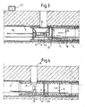
- a piece of pipe 1 to be placed in a sewer has a spigot end 2 and a socket end 3, the socket end 3 carries within it a strip df electrically conductive material 4.
- a bag 5 Before placing the pipe within the sewer a bag 5 is inserted into the pipe 1.
- the bag 5 carries an inductive coil 6 which is positioned directly adjacent the spigot end 2 of the pipe. The bag is then inflated to fix it into position.
- the pipe 1 also includes the grouting pump 7 which is attached to the nipple 8 of the pipe 1 through which the grout is pumped outside the pipe.
- the pipe 1 enters through the sewer 9 by a man-hole 10 and is pulled through the sewer 9 by a cable 11 which is attached to a winch 12.
- the pipe 1 is pulled up the sewer until the coil 6 of the bag 5 is in line with the electrically conductive strip 13 on the last fixed pipe 14.
- the pipe is fixed into position since it is grouted and therefore does not vary in length due to any temperature change.
- a deflection is shown on the voltmeter connected to the inductive coil showing that the pipe 1 is in its correct position. At this point more current is supplied to coil 6 to heat strip 13 to fuse the pipe 1 to the fixed pipe 14.
- Strip 13 is coated with a polyethylene coating 13a.
- This cycle of steps is repeated until the distance between the last pipe 14 and the next approximate position of a lateral is less than the length of a pipe.
- a bag 15 and a cage 16 which both have holes 17 along their lengths are threaded onto a metal rod 18 which is attached to the cable 11 running through the sewer 9.
- the bag and cage are then pulled along the sewer until the cage 16 meets the end of the pipe 14.
- the bag 15 is inflated to form a fixed reference position.
- the cage 16 carries a T.V. camera 19 wh3zh is movable along its length.
- the T.V. camera 19 also includes a rotatable mirror 20 which means that the camera can scan the whole of the sewer 9.
- a graduated scale 21 which shows the longitudinal position of the camera and around its circumference there is a graduated scale 22 which shows the radial position of the mirror.
- the T.V. camera 19 sends signals to a viewer 23 outside the sewer.
- the T.V. camera 19 is drawn back along the cage until a picture of the first edge of the lateral 24 is sent to the viewer 23.
- the mirror 20 is then rotated until an image of the scale 21 is sent to the viewer 23.
- the radial position of the mirror is measured from the scale 22 which is measured with respect to the fixed position 17.
- the cage 16 is then removed from the sewer 9.
- a hole 26 is then cut out of another pipe which is the correct longitudinal distance from the end of the pipe and in the correct radial position with respect to the fixed position 17 of a bag 27 which is similar to the bag 15.
- the bag 27 also carries a coil 27a to effect the welding.
- the cut pipe carries a T.V. camera 28 which is directed out of the hole 26 to check that the pipe is aligned to the lateral 29.
- the T.V. camera 28 senses that the hole is aligned to the lateral 24, a current is induced in the coil 27a to weld the cut pipe to the last pipe 14.
- the bag 26 and the T.V. camera 28 are then removed from the sewer.
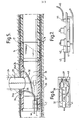
- a flexible grouting bag 31 includes a hole along its circumference so that it will be in a fixed radial position with respect to the pipe 14.
- the auxiliary grouting bag includes an elliptical hole 32 around which is sealed a flexible shuttering bag 33. Positioned around this hole are two smaller holes 34.
- the cut pipe also includes two nipples 34a.
- To the flexible bag 33 is connected a cord 35 which is used to check that the bag is in position at the lateral.
- the flexible shuttering bag 33 is in its first position where it is totally enclosed within the grouting bag 33 when it is placed in the sewer.
- the grouting pump 7 is connected to the auxiliary grouting bag 31 and moves up the sewer with it.
- the auxiliary grouting bag 31 is brought up the sewer until it is in the correct longitudinal and radial position with respect to the fixed position 17.
- the grouting pump 7 is small enough to fit in a pipe. It carries two containers 37 and 38 which hold the components of the grout. Measured quantities of each component are drawn into measuring pistons 39, 40 which are controlled by control means 41.
- the control means 41 is run by an air-logic system 42 which is controlled by pulses of air carried along pipe 43 from outside the sewer.
- the measured quantities of each component are drawn into a mixing nozzle 44 where the components are spun together rapidly to mix them thoroughly.
- the grout produced is fed from the pump through tube 45.
- the grouting material is a soluble polyurethane which expands to many times its original volume so that it forms an excellent sealant.
- Two typical components for polyurethane material are resin and isocyne 8..
- the length of the pistons 39, 40 and thus the quantity of each unit of component may be varied according to the different components and the relative volumes required to produce the grouting material.
- control mechanisms in this method such as the air control in the grouting pipe, the current to fuse the pipes together, and the control of the T.V. cameras and the inflation and deflation of the bags are all carried in one cable 46 which extends from the sewer to the control station on the ground surface.
Landscapes
- Engineering & Computer Science (AREA)
- General Engineering & Computer Science (AREA)
- Health & Medical Sciences (AREA)
- Life Sciences & Earth Sciences (AREA)
- Hydrology & Water Resources (AREA)
- Public Health (AREA)
- Water Supply & Treatment (AREA)
- Mechanical Engineering (AREA)
- Sewage (AREA)
- Lining Or Joining Of Plastics Or The Like (AREA)
Applications Claiming Priority (2)
| Application Number | Priority Date | Filing Date | Title |
|---|---|---|---|
| GB8233618 | 1982-11-24 | ||
| GB8233618 | 1982-11-24 |
Publications (2)
| Publication Number | Publication Date |
|---|---|
| EP0110664A2 true EP0110664A2 (de) | 1984-06-13 |
| EP0110664A3 EP0110664A3 (de) | 1986-04-16 |
Family
ID=10534507
Family Applications (1)
| Application Number | Title | Priority Date | Filing Date |
|---|---|---|---|
| EP83307147A Withdrawn EP0110664A3 (de) | 1982-11-24 | 1983-11-23 | Verfahren zum Renovieren von Abflussrinnen |
Country Status (3)
| Country | Link |
|---|---|
| US (1) | US4728223A (de) |
| EP (1) | EP0110664A3 (de) |
| DK (1) | DK535783A (de) |
Cited By (12)
| Publication number | Priority date | Publication date | Assignee | Title |
|---|---|---|---|---|
| EP0158042A3 (en) * | 1984-04-09 | 1986-07-23 | Wiik & Hoeglund | Method and device for incorporating plastic tubes into sewers |
| EP0192338A1 (de) * | 1985-01-24 | 1986-08-27 | Haden Drysys International Limited | Verfahren und Vorrichtung zum Beschichten der Oberfläche eines Körpers |
| WO1986005569A1 (en) * | 1985-03-13 | 1986-09-25 | Pirelli Construction Company Limited | Grouting method |
| DE3602281A1 (de) * | 1986-01-25 | 1987-07-30 | Klaus Zawisla | Vorrichtung zur behandlung unterirdisch verlegter kanalrohre |
| WO1987005365A1 (fr) * | 1986-03-03 | 1987-09-11 | Allgemeine Baugesellschaft - A. Porr Aktiengesells | Procede de renovation de canalisations menacees d'effondrement, en particulier de canalisations profilees |
| DE3618963A1 (de) * | 1986-06-05 | 1987-12-10 | Adolf Prof Dipl Ing Voss | Verfahren und vorrichtung zum verbinden eines abwasserkanales mit einem quer einmuendenden hausanschlusskanal oder dergleichen |
| WO1989003459A1 (fr) * | 1987-10-06 | 1989-04-20 | Allgemeine Baugesellschaft - A. Porr Aktiengesells | Procede de reparation de canalisations |
| DE3737301A1 (de) * | 1987-11-04 | 1989-05-18 | Hemscheidt Maschf Hermann | Verfahren und vorrichtung zum sanieren von abwasserkanalrohren |
| DE3810437A1 (de) * | 1988-03-26 | 1989-10-12 | Hemscheidt Maschf Hermann | Verfahren zum verbinden des inliners einer kanalrohrleitung mit den zulaufleitungen |
| DE3830821A1 (de) * | 1988-09-10 | 1990-03-22 | Niederberg Chemie | Verfahren und vorrichtung zum relining von kanalrohren und dergleichen |
| DE4204174A1 (de) * | 1992-02-13 | 1993-08-19 | Jt Elektronik Gmbh | Packer mit aufblasbaren dichtelementen und kolbenpumpe |
| DE19526302A1 (de) * | 1995-07-19 | 1997-01-23 | Helmar Haas | Einrichtung und Verfahren zum Herstellen von Bohrungen in sanierte unterirdisch verlegte Rohre |
Families Citing this family (38)
| Publication number | Priority date | Publication date | Assignee | Title |
|---|---|---|---|---|
| WO1987005984A1 (en) * | 1986-03-25 | 1987-10-08 | Danby Pty. Ltd. | Reinstatement of lateral branch connections in relined sewers or pipes |
| GB8726073D0 (en) * | 1987-11-06 | 1987-12-09 | Rice N | Re-lining of sewers |
| CA1279584C (en) * | 1988-04-13 | 1991-01-29 | Oy Wiik & Hoglund Ab | Sewer pipe relining method |
| US4956032A (en) * | 1988-04-28 | 1990-09-11 | Keller Industries Ltd. | Method of grouting using a vacuum |
| CH682945A5 (de) * | 1989-12-01 | 1993-12-15 | Sika Robotics Ag | Ferngesteuerter Schalungseinbau in nicht begehbaren Rohrverzweigungen und Einmündungen. |
| US5002438B1 (en) * | 1990-01-03 | 1995-05-30 | Strong Systems Inc | Method of rehabilitating manholes by custom lining/relining. |
| CH681905A5 (de) * | 1990-09-14 | 1993-06-15 | Leo Corazza | |
| GB2249603B (en) * | 1990-11-02 | 1995-05-10 | British Gas Plc | Replacing mains |
| US5674030A (en) * | 1991-08-27 | 1997-10-07 | Sika Equipment Ag. | Device and method for repairing building branch lines in inacessible sewer mains |
| US5375626A (en) * | 1991-11-08 | 1994-12-27 | Fears; Clois D. | Method of and lining for water intake pipes |
| US5527135A (en) * | 1993-03-03 | 1996-06-18 | Kabushiki Kaisha Iseki Kaihatsu Koki | Method for injecting lubricant or back-filling material into a space between the outside of double-wall pipes and the ground in the pipe-jacking method and an apparatus therefor |
| GB2275981B (en) * | 1993-03-10 | 1997-03-12 | British Gas Plc | Apparatus and method for introducing sealant into a clearance |
| US5386669A (en) * | 1993-03-15 | 1995-02-07 | Almeida; Antonio V. | Corrosion resistant leakproof plastic manhole system |
| AT400052B (de) * | 1993-05-05 | 1995-09-25 | Klug Kanal Leitungs Und | Verfahren zum auskleiden eines kanals und einbring-und rückholschlitten zur durchführungdes verfahr ens |
| AT399184B (de) * | 1993-07-14 | 1995-03-27 | Kuebel Johann | Verfahren zum dichtenden auskleiden von hohlräumen, sowie verkleidungselement, insbesondere zur durchführung dieses verfahrens |
| AT403391B (de) * | 1994-03-01 | 1998-01-26 | Klug Kanal Leitungs Und Umwelt | Verfahren zur herstellung dichter einmündungen von hausanschlussrohren und ähnlichen zuflussrohren in abwasserkanäle |
| US5527133A (en) * | 1994-08-17 | 1996-06-18 | Csillag; Robert | Tool for a sewer robot |
| US6494978B1 (en) * | 1995-02-13 | 2002-12-17 | Richard L. Bertram | Deteriorated structure repair method for restoring and lining corroded structure |
| US5564863A (en) * | 1995-03-13 | 1996-10-15 | Tti Trenchless Technologies, Inc. | Method and apparatus for point-repair of sewer and other utility lines |
| US5626442A (en) * | 1995-10-24 | 1997-05-06 | Boyer, Inc. | Pipe rehabilitation system and methods |
| US6494437B1 (en) | 1995-10-24 | 2002-12-17 | Mark L. Boyer | Boom mounted winch |
| US6967045B1 (en) | 1998-06-12 | 2005-11-22 | Bertram Richard L | Integrated composite structural conduit formed in place |
| US6673193B1 (en) | 1998-12-17 | 2004-01-06 | Linabond Inc. | System and method for welding a seam between thermoplastic liner sheets |
| DE19932647A1 (de) * | 1999-07-13 | 2001-01-18 | Stadtwerke Muenchen Gmbh | Verfahren und System zur Umfüllung eines endlos verlegten Rohrstrangs mit Füllbeton |
| GB2357988B (en) * | 2000-01-05 | 2004-04-28 | Channeline Sewer Systems Ltd | Linings for sewers |
| US7000642B2 (en) * | 2002-10-30 | 2006-02-21 | J.R. Pipeline Co., Inc. | Apparatus and method for installation of pipe liner |
| US20050016608A1 (en) * | 2003-06-13 | 2005-01-27 | Underground Solutions Technologies Group, Inc. | Fluid system for conduit expansion and mobile arrangement therefor |
| AU2004250155A1 (en) | 2003-06-13 | 2004-12-29 | Underground Solutions Technologies Group, Inc. | System and arrangement for conduit reparation |
| US20050016450A1 (en) | 2003-06-13 | 2005-01-27 | Underground Solutions Technologies Group, Inc. | System and arrangement for conduit reparation |
| US20130243533A1 (en) * | 2012-03-14 | 2013-09-19 | Concrete Alternatives & More, Inc. | Method for Installing a Helical Pier with Polyurthane Resin Grout |
| JP6423819B2 (ja) * | 2016-05-27 | 2018-11-14 | 明石セミシールド建設株式会社 | 既設管の更生方法及び既設管の更生構造 |
| GB2554866B (en) * | 2016-10-05 | 2020-12-02 | Pioneer Lining Tech Limited | Methods of joining or repairing lined pipes and associated apparatus |
| FR3058355B1 (fr) * | 2016-11-04 | 2019-10-18 | Saipem S.A. | Methode d'assemblage de tubes thermoplastiques par soudage par induction |
| DE102017109980A1 (de) * | 2017-05-09 | 2018-11-15 | Pipetronics Gmbh & Co. Kg | Vorrichtung zum Sanieren von schadhaften Leitungswandungen mit einer Heizeinrichtung zum schnelleren Aushärten der Sanierungsmasse |
| GB2569549B (en) * | 2017-12-19 | 2021-02-10 | Acergy France SAS | Electrofusion of pipe liners |
| CN112303257B (zh) * | 2020-10-31 | 2022-05-10 | 江苏明通福路流体控制设备有限公司 | 一种通用性高的带锁阀门 |
| CN113653157A (zh) * | 2021-08-16 | 2021-11-16 | 广东楠通建设工程有限公司 | 一种市政雨污管道内壁注浆修复方法 |
| US11976768B2 (en) * | 2022-04-07 | 2024-05-07 | Carboshield, Inc. | Composite reinforcement of tubular structures |
Family Cites Families (11)
| Publication number | Priority date | Publication date | Assignee | Title |
|---|---|---|---|---|
| US2794758A (en) * | 1954-09-03 | 1957-06-04 | Pan American Petroleum Corp | Method and apparatus for in-place lining of a pipeline |
| IL33199A (en) * | 1968-11-04 | 1972-10-29 | Mills D | Pipe relining method and apparatus |
| US3926345A (en) * | 1972-02-03 | 1975-12-16 | Stabilator Ab | Device for the batching of media |
| US3989228A (en) * | 1974-12-19 | 1976-11-02 | Products Research & Chemical Corporation | Mixing and dispensing apparatus |
| US3915437A (en) * | 1975-01-10 | 1975-10-28 | Goodyear Tire & Rubber | Mixing apparatus |
| US4197908A (en) * | 1978-04-06 | 1980-04-15 | Underground Surveys Corporation | Apparatus for porting a side wall of a conduit from interiorly thereof |
| US4228924A (en) * | 1978-08-23 | 1980-10-21 | Gilbert Charles H | Mixture metering machine |
| GB2041147B (en) * | 1979-01-22 | 1982-12-15 | Fusion Equipment Ltd | Renovating sewers |
| WO1980002124A1 (en) * | 1979-04-05 | 1980-10-16 | Haxey Eng Ltd | Methods for joining together thermoplastics pipes and pipe fittings |
| GB2079805B (en) * | 1980-07-05 | 1985-04-03 | Demco Ltd | Lining underground conduits |
| WO1982004086A1 (en) * | 1981-05-12 | 1982-11-25 | Rice Nigel Leonard | Pipe connecting method |
-
1983
- 1983-11-23 US US06/554,784 patent/US4728223A/en not_active Expired - Fee Related
- 1983-11-23 DK DK535783A patent/DK535783A/da not_active Application Discontinuation
- 1983-11-23 EP EP83307147A patent/EP0110664A3/de not_active Withdrawn
Cited By (14)
| Publication number | Priority date | Publication date | Assignee | Title |
|---|---|---|---|---|
| US4724108A (en) * | 1984-04-09 | 1988-02-09 | Wiik & Hoglund Gmbh | Method for the installation of plastic pipes in sewage piping |
| EP0158042A3 (en) * | 1984-04-09 | 1986-07-23 | Wiik & Hoeglund | Method and device for incorporating plastic tubes into sewers |
| EP0192338A1 (de) * | 1985-01-24 | 1986-08-27 | Haden Drysys International Limited | Verfahren und Vorrichtung zum Beschichten der Oberfläche eines Körpers |
| WO1986005569A1 (en) * | 1985-03-13 | 1986-09-25 | Pirelli Construction Company Limited | Grouting method |
| DE3602281A1 (de) * | 1986-01-25 | 1987-07-30 | Klaus Zawisla | Vorrichtung zur behandlung unterirdisch verlegter kanalrohre |
| WO1987005365A1 (fr) * | 1986-03-03 | 1987-09-11 | Allgemeine Baugesellschaft - A. Porr Aktiengesells | Procede de renovation de canalisations menacees d'effondrement, en particulier de canalisations profilees |
| US4948298A (en) * | 1986-03-03 | 1990-08-14 | Allgemeine Baugesellschaft-A. Porr Aktiengesellschaft | Process for restoring channels threatening to collapse, in particular profiled channels |
| DE3618963A1 (de) * | 1986-06-05 | 1987-12-10 | Adolf Prof Dipl Ing Voss | Verfahren und vorrichtung zum verbinden eines abwasserkanales mit einem quer einmuendenden hausanschlusskanal oder dergleichen |
| WO1989003459A1 (fr) * | 1987-10-06 | 1989-04-20 | Allgemeine Baugesellschaft - A. Porr Aktiengesells | Procede de reparation de canalisations |
| DE3737301A1 (de) * | 1987-11-04 | 1989-05-18 | Hemscheidt Maschf Hermann | Verfahren und vorrichtung zum sanieren von abwasserkanalrohren |
| DE3810437A1 (de) * | 1988-03-26 | 1989-10-12 | Hemscheidt Maschf Hermann | Verfahren zum verbinden des inliners einer kanalrohrleitung mit den zulaufleitungen |
| DE3830821A1 (de) * | 1988-09-10 | 1990-03-22 | Niederberg Chemie | Verfahren und vorrichtung zum relining von kanalrohren und dergleichen |
| DE4204174A1 (de) * | 1992-02-13 | 1993-08-19 | Jt Elektronik Gmbh | Packer mit aufblasbaren dichtelementen und kolbenpumpe |
| DE19526302A1 (de) * | 1995-07-19 | 1997-01-23 | Helmar Haas | Einrichtung und Verfahren zum Herstellen von Bohrungen in sanierte unterirdisch verlegte Rohre |
Also Published As
| Publication number | Publication date |
|---|---|
| US4728223A (en) | 1988-03-01 |
| EP0110664A3 (de) | 1986-04-16 |
| DK535783D0 (da) | 1983-11-23 |
| DK535783A (da) | 1984-05-25 |
Similar Documents
| Publication | Publication Date | Title |
|---|---|---|
| US4728223A (en) | Methods of renovating sewers | |
| CA1279584C (en) | Sewer pipe relining method | |
| EP0114727B1 (de) | Vorrichtung zum Abdichten von Abzweigleitungen | |
| US5329063A (en) | Liner assembly for lining branch pipes and a method for manufacturing the liner assembly | |
| US4991006A (en) | Apparatus using an everted hose for inspecting the interior of a lateral pipeline | |
| US7448413B2 (en) | Method of locating liner within sewer pipe | |
| EP0413495B1 (de) | Einsatzrohr für die Reparatur von Rohrleitungen | |
| US3602263A (en) | Pipe relining method and apparatus | |
| GB2041147A (en) | Renovating sewers | |
| US20140085643A1 (en) | Method and means for determining pipe diameter | |
| JP2007502227A (ja) | 導管の融着方法 | |
| IE71184B1 (en) | Improvements in methods for installing a substantially rigid thermoplastic pipe in an existing conduit | |
| US5486332A (en) | Method for everting a tubular liner bag | |
| US5527135A (en) | Method for injecting lubricant or back-filling material into a space between the outside of double-wall pipes and the ground in the pipe-jacking method and an apparatus therefor | |
| WO1986005569A1 (en) | Grouting method | |
| GB2147080A (en) | Apparatus for and method of repairing ducts | |
| GB2136912A (en) | Sealing pipes | |
| GB2098300A (en) | Improvements in and relating to the lining of sewers pipes or the like | |
| EP0078816A1 (de) | Verfahren zum verbinden von rohren | |
| EP0441982B1 (de) | Verfahren zur rohrauskleidung durch umstülpen ohne baugrube | |
| US20240093823A1 (en) | A method of relining a sewer pipe | |
| JP2586959B2 (ja) | 管路の更新方法 | |
| KR200253935Y1 (ko) | 관로 가변구간 보수장비 | |
| JPH03265798A (ja) | 既設管路の補修方法および補修用被覆体 | |
| US20070258773A1 (en) | Method and system for repairing subterranean structures |
Legal Events
| Date | Code | Title | Description |
|---|---|---|---|
| PUAI | Public reference made under article 153(3) epc to a published international application that has entered the european phase |
Free format text: ORIGINAL CODE: 0009012 |
|
| AK | Designated contracting states |
Designated state(s): AT BE CH DE FR GB IT LI LU NL SE |
|
| PUAL | Search report despatched |
Free format text: ORIGINAL CODE: 0009013 |
|
| AK | Designated contracting states |
Kind code of ref document: A3 Designated state(s): AT BE CH DE FR GB IT LI LU NL SE |
|
| 17P | Request for examination filed |
Effective date: 19861015 |
|
| 17Q | First examination report despatched |
Effective date: 19870504 |
|
| RAP1 | Party data changed (applicant data changed or rights of an application transferred) |
Owner name: PIRELLI CONSTRUCTION COMPANY LIMITED |
|
| STAA | Information on the status of an ep patent application or granted ep patent |
Free format text: STATUS: THE APPLICATION IS DEEMED TO BE WITHDRAWN |
|
| 18D | Application deemed to be withdrawn |
Effective date: 19890405 |
|
| RIN1 | Information on inventor provided before grant (corrected) |
Inventor name: RICE, NIGEL LEONARD |