EP0110733A2 - Appareil de transfert à membrane - Google Patents
Appareil de transfert à membrane Download PDFInfo
- Publication number
- EP0110733A2 EP0110733A2 EP83307449A EP83307449A EP0110733A2 EP 0110733 A2 EP0110733 A2 EP 0110733A2 EP 83307449 A EP83307449 A EP 83307449A EP 83307449 A EP83307449 A EP 83307449A EP 0110733 A2 EP0110733 A2 EP 0110733A2
- Authority
- EP
- European Patent Office
- Prior art keywords
- stack
- membrane
- conduit
- fluid
- depressions
- Prior art date
- Legal status (The legal status is an assumption and is not a legal conclusion. Google has not performed a legal analysis and makes no representation as to the accuracy of the status listed.)
- Granted
Links
Images


Classifications
-
- F—MECHANICAL ENGINEERING; LIGHTING; HEATING; WEAPONS; BLASTING
- F28—HEAT EXCHANGE IN GENERAL
- F28D—HEAT-EXCHANGE APPARATUS, NOT PROVIDED FOR IN ANOTHER SUBCLASS, IN WHICH THE HEAT-EXCHANGE MEDIA DO NOT COME INTO DIRECT CONTACT
- F28D21/00—Heat-exchange apparatus not covered by any of the groups F28D1/00 - F28D20/00
- F28D21/0015—Heat and mass exchangers, e.g. with permeable walls
-
- B—PERFORMING OPERATIONS; TRANSPORTING
- B01—PHYSICAL OR CHEMICAL PROCESSES OR APPARATUS IN GENERAL
- B01D—SEPARATION
- B01D63/00—Apparatus in general for separation processes using semi-permeable membranes
- B01D63/08—Flat membrane modules
- B01D63/082—Flat membrane modules comprising a stack of flat membranes
-
- F—MECHANICAL ENGINEERING; LIGHTING; HEATING; WEAPONS; BLASTING
- F28—HEAT EXCHANGE IN GENERAL
- F28D—HEAT-EXCHANGE APPARATUS, NOT PROVIDED FOR IN ANOTHER SUBCLASS, IN WHICH THE HEAT-EXCHANGE MEDIA DO NOT COME INTO DIRECT CONTACT
- F28D9/00—Heat-exchange apparatus having stationary plate-like or laminated conduit assemblies for both heat-exchange media, the media being in contact with different sides of a conduit wall
- F28D9/0087—Heat-exchange apparatus having stationary plate-like or laminated conduit assemblies for both heat-exchange media, the media being in contact with different sides of a conduit wall with flexible plates
Definitions
- the invention is concerned with apparatus for effecting transfer of heat or mass between two fluids, of which a first one may be blood, through a transfer membrane.
- the first fluid is blood
- the second fluid will be oxygen, in the case 'of a blood oxygenator; or dialysate in the case of a dialyser; or water at a suitable temperature in the case of a heat exchanger for blood.
- the invention is concerned with such apparatus incorporating a number of parallel channels, each channel comprising a first conduit for the first fluid formed between two closely spaced transfer membrane sheets with the outer face of each sheet supported against a profiled plate such that second conduits for the second fluid are provided one on each side of the first conduit between a respective membrane sheet and supporting plate.
- the supporting plates are mounted spaced apart in a stack with the double membrane sheets between each adjacent pair of plates.
- an inlet manifold for the first fluid has been fitted across the full width of the front of the stack and an outlet manifold for the first fluid across the full width of the back of the stack, the first fluid flowing from the inlet manifold through the parallel first conduits, each of elongate cross-section between adjacent pairs of membrane sheets, to the outlet manifold.
- the first and second fluid conduits have been separated by wrapping each support plate with transfer membrane material to provide the membrane sheets one on each face of the plate and hence one in each of an adjacent pair of channels. Sealing has been achieved by tucking the ends of the double sheet into a slot in the front or rear edge of the respective plate.
- the transfer membrane sheets are provided as parts of a continuous web of transfer membrane material which is folded in concertina fashion, one set of folds each extending around the front edge of a respective plate and the other set of folds each closing a respective first conduit adjacent to the rear of the stack; each first conduit being sealed along a narrow zone extending from a point substantially halfway along the front of the stack towards, but short of, the membrane fold adjacent to the rear of the stack, whereby each first conduit is substantially U-shaped, extending from one side of the front of the stack towards and across the rear of the stack and back to the other side of the front of the stack, or W-shaped; and inlet and outlet manifolds for the first fluid being provided alongside one another across the front of the stack.
- the essential plumbing for the first fluid can be provided at the front of the stack and the folds of transfer membrane material, extending around the front edges of the plate, provide a faired entry for the first fluid from the inlet manifold into each first conduit and a faired exit of the first fluid from each first conduit into the outlet manifold. This materially reduces the stagnation problem when the first fluid is blood.
- each first conduit may be provided with. a repetitive series of hollows, such as dimples, and the first fluid may be pumped through the conduits with a pulsatile component, superimposed on the mean flow, to promote vortex mixing of the first fluid in the first conduit, as described generally in GB-A-1,442,754.
- the hollows in the membrane material may be preformed, or formed in situ by expansion of the membrane material partly into corresponding profiling of the plates.
- the second fluid will preferably flow in countercurrent to the mean flow of the first fluid, through similarly U-shaped conduits formed on either side of and superposed over each first conduit.
- inlet and outlet manifolds for the second fluid are connected to the second fluid conduits at the sides of the stack adjacent to the front of the stack.
- the apparatus shown in Figure 1 forms part of an artificial lung and has a rectangular housing 1 with an inlet 2 and outlet 3 through which blood is fed to the housing.
- Manifolds separated by a wall 4 with a rubber sealing portion 4', enable blood to be supplied to a stack of U-shaped conduits 5 formed by a polypropylene microporous membrane 6 which is disposed in a sinuous folded path around the front of and between a plurality of stacked, spaced apart, plates 7.
- Each of the plates 7 is injection moulded from polycarbonate and has a tapered front end 8 which provides faired inlet and outlet portions to the U-shaped conduits 5 formed between the plates 7 by the membrane 6.
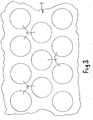
- each of the plates 7 is formed with a plurality of part-spherical depressions 9 extending in rows from a point just adjacent the front of the plate to a point well spaced from the rear of the plate.
- the depressions 9 in adjacent rows are closely packed, so that adjacent depressions 9 are substantially equi-distantly spaced apart, by offsetting adjacent rows by half the spacing between the centres of- adjacent depressions in each row.
- Connecting the depressions along each respective row is a groove 10 formed to the same depth as the depressions 9.
- the depressions 9 are shown only in the top pair of plates in Figure 1 '-and, at that, only diagrammatically.
- Figures 4 and 5 illustrate the formation of the depressions and grooves more accurately as they are drawn to a larger scale.
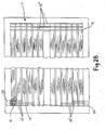
- manifold apertures 20 are formed in the front side edges of each plate as shown in Figure 2B.
- Grooves 10' feeding the oxygen from the apertures to the front ends of the slots 10 and grooves 10" feeding the oxygen across the rear of the plate between the two sides of the U-shaped path.
- each conduit 5 is formed in a U-shape as shown more particularly by Figure 2 which illustrates, in plan, one side of one of the conduits formed by the membrane 6.
- the membrane 6 is held between the plates by rubber gaskets which press against the two membrane portions and squeeze them together to form a seal.
- fold lines 11,12 At either end of the side portion of the conduit-forming membrane sheet 6 are fold lines 11,12 about which the membrane is folded at the front of the stack of plates and at the back respectively.
- the arrows B in Figure 2 illustrate the flow path of blood from and to the inlet and outlet manifolds within the conduit formed by the two superimposed areas of the membrane 6 which lie between a respective pair of the plates 7.
- the membrane In longitudinally extending areas 13 the membrane is dimpled outwardly of the conduit, the dimples 14 being provided, as with the depressions in the plates 7, in longitudinally extending rows, adjacent rows being offset by half the distance between the centres of the dimples.
- the dimples 14 are preferably formed in the membrane prior to it being folded and stacked with the plates 7, but it is envisaged that when the membrane is formed of thermoplastic materials, the dimples could be formed in situ from an essentially planar membrane, by passing, for example hot water, under pressure through the conduits after initial assembly so as to stretch the membrane into the depressions 9 to form the dimples 14.
- Longitudinal ribs 15 separate the adjacent longitudinal dimpled sections 13 and in the centre of the membrane a wider rib portion 16 is provided, the two sheet portions of the membrane 6 which form each side of a conduit being sealed to one another along this portion 16 so as to define the generally U-shaped path for the blood.
- Each of the plates 7 has a corresponding rib portion (not shown) of substantially the same length as the portion 16, the opposed rib portions on adjacent plates squeezing the membrane between them so as to produce the seal along the portion 16.
- Side portions 17 on each side of the conduit are likewise sealed between corresponding side portions of adjacent plates 7 to seal the edges of the conduit.
- the flow of oxygen through the artificial lung also follows a U-shaped path around each conduit 5, the oxygen being fed from the apertures 20, through the grooves 10', under the dimpled portions 14, through the depressions 9 and the grooves 10, and across the undimpled portion 18 of the conduit through the grooves 10" and then back down a similar path on the other side.
- Oxygen is fed to the apertures through suitable ducts (not shown).
- the dimples in the membrane sheet 6 and the depressions 9 are arranged in alignment with one another so that, as shown in Figure 5,- the dimples 14 extend partly into the depressions 9.
- Each of the dimples and depressions has a diameter of substantially 1.5 mm., the dimples having a depth of 0.5 mm. and the depressions a depth of 1 mm., the grooves 10 having a width of 0.5 mm. and a depth, the same as the depressions, i.e. 1 mm.
- the portions of the plates 7 which have the depressions formed in them are spaced apart a distance of 0.5 mm.
- blood is pumped through the artificial lung preferably with a pulsatile flow, for example, by means of a pair of rolling-diaphragm piston pumps which may be located in the respective manifolds and which are operated in anti-phase to produce oscillating blood flow inside the lung.
- Blood will thus flow in a plurality of U-shaped paths through the conduits 5 formed by the folded membrane 6.
- the blood flows with a mean flow velocity through the conduits 5, but the superimposed reciprocatory component causes the blood alternately to accelerate and decelerate and this sets up eddies or vortices in the dimples 14 to promote intimate mixing of the blood and contact between the blood and the transfer membrane.
- oxygen is pumped in a steady stream through the housing in countercurrent to the flow of blood, also in U-shaped paths between the conduits 5 formed by the membrane and the plates 7.
- the countercurrent flow of oxygen produces good transfer through the membrane walls of the conduits.
Landscapes
- Engineering & Computer Science (AREA)
- Physics & Mathematics (AREA)
- Thermal Sciences (AREA)
- Mechanical Engineering (AREA)
- General Engineering & Computer Science (AREA)
- Chemical & Material Sciences (AREA)
- Chemical Kinetics & Catalysis (AREA)
- Separation Using Semi-Permeable Membranes (AREA)
- External Artificial Organs (AREA)
- Heat-Exchange Devices With Radiators And Conduit Assemblies (AREA)
Priority Applications (1)
| Application Number | Priority Date | Filing Date | Title |
|---|---|---|---|
| AT83307449T ATE28797T1 (de) | 1982-12-07 | 1983-12-07 | Vorrichtung zur uebertragung mit einer membran. |
Applications Claiming Priority (4)
| Application Number | Priority Date | Filing Date | Title |
|---|---|---|---|
| GB8234893 | 1982-12-07 | ||
| GB8234892 | 1982-12-07 | ||
| GB8234893 | 1982-12-07 | ||
| GB8234892 | 1982-12-07 |
Publications (3)
| Publication Number | Publication Date |
|---|---|
| EP0110733A2 true EP0110733A2 (fr) | 1984-06-13 |
| EP0110733A3 EP0110733A3 (en) | 1984-07-11 |
| EP0110733B1 EP0110733B1 (fr) | 1987-08-12 |
Family
ID=26284622
Family Applications (1)
| Application Number | Title | Priority Date | Filing Date |
|---|---|---|---|
| EP83307449A Expired EP0110733B1 (fr) | 1982-12-07 | 1983-12-07 | Appareil de transfert à membrane |
Country Status (7)
| Country | Link |
|---|---|
| US (1) | US4636310A (fr) |
| EP (1) | EP0110733B1 (fr) |
| JP (1) | JPS60500005A (fr) |
| AT (1) | ATE28797T1 (fr) |
| AU (1) | AU2336784A (fr) |
| DE (1) | DE3372917D1 (fr) |
| WO (1) | WO1984002276A1 (fr) |
Families Citing this family (14)
| Publication number | Priority date | Publication date | Assignee | Title |
|---|---|---|---|---|
| CH670573A5 (fr) * | 1985-11-22 | 1989-06-30 | Sulzer Ag | |
| GB8725636D0 (en) * | 1987-11-02 | 1987-12-09 | Bellhouse Brian John | Transfer membrane apparatus |
| EP0487576B1 (fr) * | 1989-08-17 | 1995-02-15 | Brian John Bellhouse | Procede et appareil de transfert de chaleur ou de masse a travers une membrane a l'aide de tourbillons |
| US5217627A (en) * | 1990-11-06 | 1993-06-08 | Pall Corporation | System and method for processing biological fluid |
| CA2074671A1 (fr) * | 1991-11-04 | 1993-05-05 | Thomas Bormann | Dispositif et methode permettant de separer le plasma d'un liquide biologique |
| US7759113B2 (en) * | 1999-04-30 | 2010-07-20 | The General Hospital Corporation | Fabrication of tissue lamina using microfabricated two-dimensional molds |
| CN1450930A (zh) * | 2000-03-23 | 2003-10-22 | W·L·戈尔有限公司 | 软管装置 |
| US7776021B2 (en) * | 2000-04-28 | 2010-08-17 | The Charles Stark Draper Laboratory | Micromachined bilayer unit for filtration of small molecules |
| US20040060867A1 (en) * | 2002-09-27 | 2004-04-01 | Bmc Industries, Inc. | Membrane support devices and methods of manufacturing |
| WO2004065616A2 (fr) | 2003-01-16 | 2004-08-05 | The General Hospital Corporation | Utilisation de systemes microfabriques tridimensionnels du genie tissulaire pour applications pharmacologiques |
| WO2005034624A2 (fr) | 2003-05-21 | 2005-04-21 | The General Hospital Corporation | Compositions microfabriquees et procedes de genie tissulaire permettant d'obtenir des tissus contenant des types cellulaires multiples |
| EP3463507B1 (fr) * | 2016-05-27 | 2025-05-14 | The Charles Stark Draper Laboratory, Inc. | Dispositif microfluidique biomimétique pour l'élimination de dioxyde de carbone à haut rendement chez des patients à des débits sanguins faibles |
| CN114593623B (zh) * | 2022-03-30 | 2023-10-20 | 内蒙古工业大学 | 一种可自动调整换热面积的换热器 |
| CN115518219B (zh) * | 2022-08-30 | 2023-06-16 | 四川大学华西医院 | 一种低容量活化白细胞吸附器 |
Family Cites Families (13)
| Publication number | Priority date | Publication date | Assignee | Title |
|---|---|---|---|---|
| US3907687A (en) * | 1968-12-07 | 1975-09-23 | Baxter Laboratories Inc | Plate dialyzer |
| US3724673A (en) * | 1970-08-28 | 1973-04-03 | Gen Electric | Textured membranes for blood dialyzers oxygenators and the like |
| GB1442754A (en) * | 1972-06-28 | 1976-07-14 | Nat Res Dev | Apparatus for and method of effecting heat or mass transfer berween fluids |
| US3910841A (en) * | 1974-04-02 | 1975-10-07 | William G Esmond | Stacked exchange device |
| GB1595058A (en) * | 1976-10-22 | 1981-08-05 | Bellhouse Brian John | Membrane blood oxygenators |
| US4115273A (en) * | 1976-11-15 | 1978-09-19 | Extracorporeal Medical Specialties, Inc. | Wave patterned support for dialyzer membrane |
| JPS5450196A (en) * | 1977-09-28 | 1979-04-19 | Kato Isamu | Method of dialyzing blood in artificial kidney |
| DE2754220C2 (de) * | 1977-12-06 | 1982-10-28 | SECON Gesellschaft für Separations- und Concentrationstechnik mbH, 3400 Göttingen | Dialysator |
| DE2810949A1 (de) * | 1978-03-14 | 1979-10-11 | Sigdell Jan Erik Dr | Membrantraegerstruktur fuer kuenstliche nieren |
| US4351797A (en) * | 1978-11-08 | 1982-09-28 | Bellhouse Brian John | Transfer membrane assembly |
| GB2048114B (en) * | 1978-11-22 | 1983-02-09 | Bellhouse Brian John | Transfer membrane apparatus |
| US4383921A (en) * | 1979-11-21 | 1983-05-17 | Bellhouse Brian John | Apparatus for heat or mass transfer |
| WO1981002681A1 (fr) * | 1980-03-19 | 1981-10-01 | Gambro Ag | Dispositif de diffusion de substances entre deux fluides via des membranes semi-permeables |
-
1983
- 1983-12-07 DE DE8383307449T patent/DE3372917D1/de not_active Expired
- 1983-12-07 AU AU23367/84A patent/AU2336784A/en not_active Abandoned
- 1983-12-07 US US06/629,837 patent/US4636310A/en not_active Expired - Fee Related
- 1983-12-07 WO PCT/GB1983/000325 patent/WO1984002276A1/fr not_active Ceased
- 1983-12-07 AT AT83307449T patent/ATE28797T1/de active
- 1983-12-07 EP EP83307449A patent/EP0110733B1/fr not_active Expired
- 1983-12-07 JP JP59500104A patent/JPS60500005A/ja active Pending
Also Published As
| Publication number | Publication date |
|---|---|
| ATE28797T1 (de) | 1987-08-15 |
| EP0110733A3 (en) | 1984-07-11 |
| DE3372917D1 (en) | 1987-09-17 |
| EP0110733B1 (fr) | 1987-08-12 |
| AU2336784A (en) | 1984-07-05 |
| JPS60500005A (ja) | 1985-01-10 |
| WO1984002276A1 (fr) | 1984-06-21 |
| US4636310A (en) | 1987-01-13 |
Similar Documents
| Publication | Publication Date | Title |
|---|---|---|
| EP0111423B1 (fr) | Appareil de transfert à membrane | |
| US4636310A (en) | Transfer membrane apparatus | |
| CA1136057A (fr) | Appareil de transfert a diaphragme | |
| US4110220A (en) | Mass transfer device | |
| US4075091A (en) | Method for effecting heat or mass transfer | |
| EP0487576B1 (fr) | Procede et appareil de transfert de chaleur ou de masse a travers une membrane a l'aide de tourbillons | |
| HU216182B (hu) | Töltet | |
| WO2002076529A1 (fr) | Dispositif de traitement de sang | |
| US6217208B1 (en) | Heatable static mixing device with undulating or zigzag bars | |
| CA1054069A (fr) | Dialyseur a plaques | |
| EP0856351A3 (fr) | Appareil d'électrodialyse | |
| EP0018823B1 (fr) | Echangeur de chaleur en matériau thermoplastique | |
| US4351797A (en) | Transfer membrane assembly | |
| EP0086503A2 (fr) | Appareil pour la diffusion de substances entre deux fluides au moyen de membranes semi-perméables | |
| US4450903A (en) | Plate type heat exchanger with transverse hollow slotted bar | |
| EP0387270B1 (fr) | Appareil a membrane de transfert | |
| US4054527A (en) | Countercurrent capillary transfer device | |
| CN210321338U (zh) | 基于圆形微通道波浪面换热板的板壳式换热器 | |
| US3729098A (en) | Treating blood | |
| GB2024653A (en) | Mass transfer device | |
| JPH0417351B2 (fr) | ||
| GB1592772A (en) | Apparatus for heat or mass transfer |
Legal Events
| Date | Code | Title | Description |
|---|---|---|---|
| PUAI | Public reference made under article 153(3) epc to a published international application that has entered the european phase |
Free format text: ORIGINAL CODE: 0009012 |
|
| PUAL | Search report despatched |
Free format text: ORIGINAL CODE: 0009013 |
|
| AK | Designated contracting states |
Designated state(s): AT BE CH DE FR GB IT LI LU NL SE |
|
| AK | Designated contracting states |
Designated state(s): AT BE CH DE FR GB IT LI LU NL SE |
|
| 17P | Request for examination filed |
Effective date: 19841116 |
|
| GRAA | (expected) grant |
Free format text: ORIGINAL CODE: 0009210 |
|
| AK | Designated contracting states |
Kind code of ref document: B1 Designated state(s): AT BE CH DE FR GB IT LI LU NL SE |
|
| PG25 | Lapsed in a contracting state [announced via postgrant information from national office to epo] |
Ref country code: NL Effective date: 19870812 Ref country code: LI Effective date: 19870812 Ref country code: CH Effective date: 19870812 Ref country code: BE Effective date: 19870812 Ref country code: AT Effective date: 19870812 |
|
| REF | Corresponds to: |
Ref document number: 28797 Country of ref document: AT Date of ref document: 19870815 Kind code of ref document: T |
|
| ITF | It: translation for a ep patent filed | ||
| PG25 | Lapsed in a contracting state [announced via postgrant information from national office to epo] |
Ref country code: SE Effective date: 19870831 |
|
| ET | Fr: translation filed | ||
| REF | Corresponds to: |
Ref document number: 3372917 Country of ref document: DE Date of ref document: 19870917 |
|
| REG | Reference to a national code |
Ref country code: CH Ref legal event code: PL |
|
| NLV1 | Nl: lapsed or annulled due to failure to fulfill the requirements of art. 29p and 29m of the patents act | ||
| PLBE | No opposition filed within time limit |
Free format text: ORIGINAL CODE: 0009261 |
|
| STAA | Information on the status of an ep patent application or granted ep patent |
Free format text: STATUS: NO OPPOSITION FILED WITHIN TIME LIMIT |
|
| 26N | No opposition filed | ||
| ITTA | It: last paid annual fee | ||
| REG | Reference to a national code |
Ref country code: GB Ref legal event code: 732 |
|
| PGFP | Annual fee paid to national office [announced via postgrant information from national office to epo] |
Ref country code: GB Payment date: 19910125 Year of fee payment: 8 |
|
| PGFP | Annual fee paid to national office [announced via postgrant information from national office to epo] |
Ref country code: FR Payment date: 19910212 Year of fee payment: 8 |
|
| PGFP | Annual fee paid to national office [announced via postgrant information from national office to epo] |
Ref country code: LU Payment date: 19910225 Year of fee payment: 8 |
|
| PGFP | Annual fee paid to national office [announced via postgrant information from national office to epo] |
Ref country code: DE Payment date: 19910228 Year of fee payment: 8 |
|
| EPTA | Lu: last paid annual fee | ||
| PG25 | Lapsed in a contracting state [announced via postgrant information from national office to epo] |
Ref country code: LU Free format text: LAPSE BECAUSE OF NON-PAYMENT OF DUE FEES Effective date: 19911207 Ref country code: GB Effective date: 19911207 |
|
| GBPC | Gb: european patent ceased through non-payment of renewal fee | ||
| PG25 | Lapsed in a contracting state [announced via postgrant information from national office to epo] |
Ref country code: FR Effective date: 19920831 |
|
| PG25 | Lapsed in a contracting state [announced via postgrant information from national office to epo] |
Ref country code: DE Effective date: 19920901 |
|
| REG | Reference to a national code |
Ref country code: FR Ref legal event code: ST |