EP0110744A1 - Radial- und Axialbefestigung einer Verdichterschaufel - Google Patents
Radial- und Axialbefestigung einer Verdichterschaufel Download PDFInfo
- Publication number
- EP0110744A1 EP0110744A1 EP83402057A EP83402057A EP0110744A1 EP 0110744 A1 EP0110744 A1 EP 0110744A1 EP 83402057 A EP83402057 A EP 83402057A EP 83402057 A EP83402057 A EP 83402057A EP 0110744 A1 EP0110744 A1 EP 0110744A1
- Authority
- EP
- European Patent Office
- Prior art keywords
- wedge
- blade
- foot
- sheath
- engaged
- Prior art date
- Legal status (The legal status is an assumption and is not a legal conclusion. Google has not performed a legal analysis and makes no representation as to the accuracy of the status listed.)
- Granted
Links
- 229920001971 elastomer Polymers 0.000 claims abstract description 8
- 239000000806 elastomer Substances 0.000 claims abstract description 8
- 239000000463 material Substances 0.000 claims abstract description 5
- 238000011144 upstream manufacturing Methods 0.000 claims description 4
- 239000013536 elastomeric material Substances 0.000 claims description 2
- 238000000605 extraction Methods 0.000 claims description 2
- 230000036316 preload Effects 0.000 claims description 2
- 230000014759 maintenance of location Effects 0.000 abstract description 2
- 238000013016 damping Methods 0.000 description 2
- 229910052751 metal Inorganic materials 0.000 description 2
- 241000272165 Charadriidae Species 0.000 description 1
- 229910000831 Steel Inorganic materials 0.000 description 1
- 210000003323 beak Anatomy 0.000 description 1
- 238000000576 coating method Methods 0.000 description 1
- 238000012423 maintenance Methods 0.000 description 1
- 238000004519 manufacturing process Methods 0.000 description 1
- 239000002184 metal Substances 0.000 description 1
- 238000012986 modification Methods 0.000 description 1
- 230000004048 modification Effects 0.000 description 1
- 230000000284 resting effect Effects 0.000 description 1
- 125000006850 spacer group Chemical group 0.000 description 1
- 239000010959 steel Substances 0.000 description 1
Images

Classifications
-
- F—MECHANICAL ENGINEERING; LIGHTING; HEATING; WEAPONS; BLASTING
- F01—MACHINES OR ENGINES IN GENERAL; ENGINE PLANTS IN GENERAL; STEAM ENGINES
- F01D—NON-POSITIVE DISPLACEMENT MACHINES OR ENGINES, e.g. STEAM TURBINES
- F01D5/00—Blades; Blade-carrying members; Heating, heat-insulating, cooling or antivibration means on the blades or the members
- F01D5/30—Fixing blades to rotors; Blade roots ; Blade spacers
- F01D5/32—Locking, e.g. by final locking blades or keys
- F01D5/323—Locking of axial insertion type blades by means of a key or the like parallel to the axis of the rotor
Definitions
- the present invention relates to an axial and radial retaining device for fan blades.
- Axial and radial blade retaining devices are known, such as that described in French patent 2,345,605, which consists of a shim which is placed between the foot of the blade and the bottom of a groove or recess provided in the rim of the rotor disc so as to press the part of the blade root dovetail radially furthest from the axis against the lateral teeth of the groove, the wedge being held in the axial direction by a U-shaped lock which cooperates with corresponding notches provided in the root of the blade and in the teeth of the groove.
- This device also includes a corner interposed between the beak of the wedge and the front of the blade root.
- the centrifugal force exerted on the blades is no longer sufficient to keep the blade roots pressed at the same time on the two oblique faces of the grooves.
- the blades pass from a support position on one side of the cell to a support position on the other side. This produces a rattling and, what is more serious, a mat which very seriously damages the surfaces in contact. If such damage is already difficult to accept for easily replaceable parts, such as shims or, if need be, the blades, it is not the same for the rotor disc for which such damage is absolutely unacceptable.
- French patent 2,029,000 relates to a device for radial attachment of a fan blade comprising a shim made of molded elastomer material interposed between the root of the blade and the bottom of the groove or cell.
- This elastomer spacer plays a role of damping and reduction of the friction zones between the foot of the blade and the cell; however, this device does not include a metallic element under stress exerting a significant force against the blade root.
- French patent 2,376,958 is also known, which relates to a vibration damping device consisting of an element made of elastomer material in which an elastically deformable metal part is embedded.
- the thin steel sheet molded in the elastomer does not really exert a force in the radial direction on the blades, but acts only to keep the damper in contact with the plates.
- the present invention relates to a device for exerting on the foot of the blade a significant effort in the radial direction and to improve the resistance of the coatings applied to the bulb of the blade root or on the sides of the disc alveoli.
- an axial and radial fan blade retention device in which the blade comprises a dovetail foot capable of being engaged by axial sliding in corresponding cells of the rim of the rotor disc, the rim of the disc having, at its periphery, teeth projecting axially towards the front, provided with radial grooves arranged opposite one another and in which is housed an axial locking means of the blade root, the device comprising an elastic shim interposed between the blade root and the bottom of the groove to exert on the foot of the blade a force directed radially outwards and a wedge for preloading the wedge, interposed between the wedge and the lower front face of the blade foot, characterized in that it comprises a sheath made of elastomeric material in the form of a gutter extending axially and interposed between the wedge, the sides and the bottom of the cell, said sheath having an opening in which is engaged a stop of the wedge constituting a central bearing of the wedge on the bottom of the cell.
- the sheath ensures the centering of the shim in the cell and it also performs the function of axial stop. Furthermore, this elastomer sheath is interposed between the sides of the cell and the wedge and it reduces the surface of the areas in contact.
- the shims can be cut from a stretched or machined profile, so that this results in simplified and less costly manufacture.
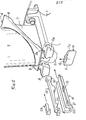
- FIGS 1 and 2 there is shown a disc 1 of a fan rotor having a rim in which are formed axially oriented cells or grooves 2 having in section the shape of a dovetail.
- each of the cells 2 is engaged by axial sliding a foot 3 of a blade 4 which comprises a blade 5, a platform 6 and a stilt 7 connecting the blade to the foot 3.
- the foot 3 has a tail-shaped section dovetail corresponding to that of groove 2.
- the rim of the disc 1 has at its periphery teeth 8, 8a projecting axially forwardly provided with radial grooves 9, 9a arranged opposite one another and in which is housed a member 10 for axial locking of the foot 3 of dawn.
- the locking member 10 consists of a rectangular parallelepiped whose lateral edges 11, lla rounded are engaged in the radial grooves 9, 9a and which has on its outer edge a tongue 12 abutting under the upstream edge of the plate -form 6 of dawn ( Figure 2).
- a stop 14 located in its central part is engaged in an opening or cut 15 of a sheath 16 of elastomer material in the form of gutter extending axially and interposed between the wedge 13, the sides and the bottom of the cell 2.
- the central stop 14 which bears against the bottom of the cell 2 constitutes a central bearing of the wedge 13 on the bottom of the cell and ensures by its engagement in the opening 15 of the sheath the axial maintenance of the wedge.
- the wedge 13 further comprises a safety stop 20, also engaged in an opening 21 of the sheath.
- the elastic wedge 13 has at the front a spout 17 comprising a hole 18 to facilitate its extraction by means of a tool; at the rear, the wedge has a stop 19 which bears against the foot 3 of the blade.
- the sheath 16 engaged in the cell 2 has at the front a spoiler 22 bearing against the front face of the disc 1.
- a wedge 23 which maintains the preload of the wedge 13, said wedge being held by a front cover 24 fixed by means of screws 25 to the disc 1.
- the foot 3 of the blade is slid into the cell 2 until its upstream face is flush with the upstream face of the disc 1.
- the blade 4 is locked axially by means of the locking member 10 which is introduced from the inside to the outside into the grooves 9, 9a of the disc.
- the locking member 10 abuts by its tongue 12 against the internal face of the platform 6, and it is held in this position by means of a clamp.
- the wedge 13 is inserted into the sheath 16, the stop 14 being engaged in the opening 15 of the sheath.
- the assembly thus constituted by the wedge 13 and the sheath 16 is engaged in the cavity 2 of the disc, under the foot 3 of the blade, until the spoiler 22 abuts against the front face of the disc 1 You can then remove the clamp holding the locking member.
- the elastic wedge 13 is curved towards the axis of the machine. After the introduction of the wedge 23 between the wedge and the foot of the blade, the wedge is released, so that, by reaction, the elastic wedge 13 presses the foot 3 of the blade against the flanks of the disc.
- the corner 23 is then locked in place by means of the front cover 24 fixed to the disc.
Landscapes
- Engineering & Computer Science (AREA)
- Mechanical Engineering (AREA)
- General Engineering & Computer Science (AREA)
- Structures Of Non-Positive Displacement Pumps (AREA)
Applications Claiming Priority (2)
| Application Number | Priority Date | Filing Date | Title |
|---|---|---|---|
| FR8218653 | 1982-11-08 | ||
| FR8218653A FR2535794A1 (fr) | 1982-11-08 | 1982-11-08 | Dispositif de retenue axiale et radiale d'aubes de soufflante |
Publications (2)
| Publication Number | Publication Date |
|---|---|
| EP0110744A1 true EP0110744A1 (de) | 1984-06-13 |
| EP0110744B1 EP0110744B1 (de) | 1986-10-01 |
Family
ID=9278974
Family Applications (1)
| Application Number | Title | Priority Date | Filing Date |
|---|---|---|---|
| EP83402057A Expired EP0110744B1 (de) | 1982-11-08 | 1983-10-24 | Radial- und Axialbefestigung einer Verdichterschaufel |
Country Status (5)
| Country | Link |
|---|---|
| US (1) | US4478554A (de) |
| EP (1) | EP0110744B1 (de) |
| JP (1) | JPS59101599A (de) |
| DE (1) | DE3366620D1 (de) |
| FR (1) | FR2535794A1 (de) |
Cited By (8)
| Publication number | Priority date | Publication date | Assignee | Title |
|---|---|---|---|---|
| GB2262139A (en) * | 1991-12-04 | 1993-06-09 | Rolls Royce Plc | Fan blade retainer |
| EP0699824A1 (de) * | 1994-08-29 | 1996-03-06 | Mtu Motoren- Und Turbinen-Union MàNchen Gmbh | Einrichtung zur Laufschaufelfixierung und zur Beseitigung von Rotorwuchten bei axial durchströmten Verdichtern oder Turbinen von Gasturbinentriebwerken |
| WO2011018425A1 (fr) * | 2009-08-11 | 2011-02-17 | Snecma | Cale amortisseuse de vibrations pour aube de soufflante |
| FR2974864A1 (fr) * | 2011-05-04 | 2012-11-09 | Snecma | Rotor de turbomachine avec moyen de retenue axiale des aubes |
| EP2865849A1 (de) * | 2013-10-22 | 2015-04-29 | Rolls-Royce plc | Rückhalteplatte |
| WO2018093473A1 (en) * | 2016-11-18 | 2018-05-24 | General Electric Company | Turbomachine bucket with radial support, shim and related turbomachine rotor |
| EP4036374A1 (de) * | 2021-02-02 | 2022-08-03 | Doosan Heavy Industries & Construction Co., Ltd. | Drehmaschine mit einer rotorscheibe und schaufeln |
| US11555407B2 (en) | 2020-05-19 | 2023-01-17 | General Electric Company | Turbomachine rotor assembly |
Families Citing this family (41)
| Publication number | Priority date | Publication date | Assignee | Title |
|---|---|---|---|---|
| FR2566061B1 (fr) * | 1984-06-14 | 1988-09-02 | Snecma | Dispositif de verrouillage axial d'une aube de turbomachine |
| FR2585069B1 (fr) * | 1985-07-16 | 1989-06-09 | Snecma | Dispositif de limitation du debattement angulaire d'aubes montees sur un disque de rotor de turbomachine |
| US5205714A (en) * | 1990-07-30 | 1993-04-27 | General Electric Company | Aircraft fan blade damping apparatus |
| JPH04161698A (ja) * | 1990-10-26 | 1992-06-05 | K F C:Kk | トンネルのコンクリート覆工施工法 |
| US5282720A (en) * | 1992-09-15 | 1994-02-01 | General Electric Company | Fan blade retainer |
| GB9223593D0 (en) * | 1992-11-11 | 1992-12-23 | Rolls Royce Plc | Gas turbine engine fan blade assembly |
| US5350279A (en) * | 1993-07-02 | 1994-09-27 | General Electric Company | Gas turbine engine blade retainer sub-assembly |
| FR2715975B1 (fr) * | 1994-02-10 | 1996-03-29 | Snecma | Rotor de turbomachine à rainures d'aube débouchantes axiales ou inclinées. |
| FR2728299B1 (fr) * | 1994-12-14 | 1997-01-24 | Snecma | Dispositif de fixation axiale d'aubes de rotor de turboreacteur |
| FR2746456B1 (fr) * | 1996-03-21 | 1998-04-30 | Snecma | Dispositif de retenue du pied des aubes d'une soufflante |
| ITMI991210A1 (it) * | 1999-05-31 | 2000-12-01 | Nuovo Pignone Spa | Dispositivo di fissaggio per palette per turbine a gas |
| FR2803623B1 (fr) * | 2000-01-06 | 2002-03-01 | Snecma Moteurs | Agencement de retenue axiale d'aubes dans un disque |
| US6520742B1 (en) * | 2000-11-27 | 2003-02-18 | General Electric Company | Circular arc multi-bore fan disk |
| US6739837B2 (en) | 2002-04-16 | 2004-05-25 | United Technologies Corporation | Bladed rotor with a tiered blade to hub interface |
| GB0216951D0 (en) * | 2002-07-20 | 2002-08-28 | Rolls Royce Plc | A fan blade assembly |
| JP2005273646A (ja) * | 2004-02-25 | 2005-10-06 | Mitsubishi Heavy Ind Ltd | 動翼体及びこの動翼体を有する回転機械 |
| FR2888897B1 (fr) * | 2005-07-21 | 2007-10-19 | Snecma | Dispositif d'amortissement des vibrations d'un anneau de retention axiale des aubes de soufflante d'une turbomachine |
| FR2889264B1 (fr) * | 2005-07-29 | 2007-11-02 | Snecma | Verrouillage des aubes dans un rotor de soufflante |
| US20080226455A1 (en) * | 2007-03-15 | 2008-09-18 | Grimesey Daren T | Quick click |
| US8485785B2 (en) | 2007-07-19 | 2013-07-16 | Siemens Energy, Inc. | Wear prevention spring for turbine blade |
| US8182229B2 (en) * | 2008-01-14 | 2012-05-22 | General Electric Company | Methods and apparatus to repair a rotor disk for a gas turbine |
| US8894370B2 (en) * | 2008-04-04 | 2014-11-25 | General Electric Company | Turbine blade retention system and method |
| FR2930595B1 (fr) * | 2008-04-24 | 2011-10-14 | Snecma | Rotor de soufflante d'une turbomachine ou d'un moteur d'essai |
| EP2184443A1 (de) | 2008-11-05 | 2010-05-12 | Siemens Aktiengesellschaft | Gasturbine mit Sicherungsplatte zwischen Schaufelfuss und Scheibe |
| FR2945329B1 (fr) * | 2009-05-06 | 2011-06-03 | Snecma | Rotor de soufflante d'un turboracteur d'avion |
| US8439635B2 (en) * | 2009-05-11 | 2013-05-14 | Rolls-Royce Corporation | Apparatus and method for locking a composite component |
| US8215915B2 (en) * | 2009-05-15 | 2012-07-10 | Siemens Energy, Inc. | Blade closing key system for a turbine engine |
| GB0914969D0 (en) * | 2009-08-28 | 2009-09-30 | Rolls Royce Plc | An aerofoil blade assembly |
| GB2474449B (en) * | 2009-10-14 | 2012-02-22 | Rolls Royce Plc | Annulus filler element for a rotor of a turbomachine |
| US8876479B2 (en) | 2011-03-15 | 2014-11-04 | United Technologies Corporation | Damper pin |
| US8951014B2 (en) * | 2011-03-15 | 2015-02-10 | United Technologies Corporation | Turbine blade with mate face cooling air flow |
| DE102013205948B4 (de) * | 2013-04-04 | 2015-03-12 | MTU Aero Engines AG | Sicherungssystem und Verfahren zur Sicherung eines Befestigungsbereichs wenigstens einer Rotorschaufel oder eines Rotorschaufelsegments in einem Montagebereich eines Rotorgrundkörpers |
| US9970297B2 (en) | 2014-08-29 | 2018-05-15 | Rolls-Royce Corporation | Composite fan slider with nano-coating |
| US10215035B2 (en) * | 2014-12-29 | 2019-02-26 | Rolls-Royce North American Technologies Inc. | Turbine wheels with preloaded blade attachment |
| EP3073052B1 (de) * | 2015-02-17 | 2018-01-24 | Rolls-Royce Corporation | Bläserbaugruppe |
| GB201503303D0 (en) | 2015-02-27 | 2015-04-15 | Rolls Royce Plc | Retention device |
| US10472975B2 (en) * | 2015-09-03 | 2019-11-12 | General Electric Company | Damper pin having elongated bodies for damping adjacent turbine blades |
| FR3057908B1 (fr) * | 2016-10-21 | 2019-11-22 | Safran Aircraft Engines | Ensemble rotatif d'une turbomachine muni d'un systeme de maintien axial d'une aube |
| FR3075284B1 (fr) * | 2017-12-18 | 2020-09-04 | Safran Aircraft Engines | Dispositif amortisseur |
| CN115751480A (zh) * | 2021-09-03 | 2023-03-07 | 广东美的暖通设备有限公司 | 风机组件、空调室外机及空调器 |
| US12410720B2 (en) * | 2023-11-02 | 2025-09-09 | General Electric Company | Turbine engine having a rotatable disk and a blade |
Citations (7)
| Publication number | Priority date | Publication date | Assignee | Title |
|---|---|---|---|---|
| FR1570396A (de) * | 1967-09-21 | 1969-06-06 | ||
| US3832092A (en) * | 1973-10-19 | 1974-08-27 | Gen Electric | Device for locking turbomachinery blades |
| US3936234A (en) * | 1975-02-10 | 1976-02-03 | General Electric Company | Device for locking turbomachinery blades |
| US4033705A (en) * | 1976-04-26 | 1977-07-05 | The United States Of America As Represented By The Administrator Of The National Aeronautics And Space Administration | Blade retainer assembly |
| FR2426151A1 (fr) * | 1978-05-18 | 1979-12-14 | Gen Electric | Dispositif de blocage des aubes de rotor |
| GB2026101A (en) * | 1978-07-22 | 1980-01-30 | Rolls Royce | Rotor blade fixing |
| GB2038959A (en) * | 1979-01-02 | 1980-07-30 | Gen Electric | Turbomachinery blade retaining assembly |
Family Cites Families (3)
| Publication number | Priority date | Publication date | Assignee | Title |
|---|---|---|---|---|
| US3653781A (en) * | 1970-12-18 | 1972-04-04 | Gen Electric | Turbomachinery blade retainer |
| GB1491480A (en) * | 1975-07-28 | 1977-11-09 | Rolls Royce | Fixing blades for fluid flow machines |
| FR2502690B1 (fr) * | 1981-03-27 | 1985-09-13 | Snecma | Dispositif de verrouillage d'aubes de soufflante et de fixation de capot avant d'un turboreacteur |
-
1982
- 1982-11-08 FR FR8218653A patent/FR2535794A1/fr active Granted
-
1983
- 1983-10-18 US US06/542,972 patent/US4478554A/en not_active Expired - Lifetime
- 1983-10-24 DE DE8383402057T patent/DE3366620D1/de not_active Expired
- 1983-10-24 EP EP83402057A patent/EP0110744B1/de not_active Expired
- 1983-11-07 JP JP58208902A patent/JPS59101599A/ja active Granted
Patent Citations (7)
| Publication number | Priority date | Publication date | Assignee | Title |
|---|---|---|---|---|
| FR1570396A (de) * | 1967-09-21 | 1969-06-06 | ||
| US3832092A (en) * | 1973-10-19 | 1974-08-27 | Gen Electric | Device for locking turbomachinery blades |
| US3936234A (en) * | 1975-02-10 | 1976-02-03 | General Electric Company | Device for locking turbomachinery blades |
| US4033705A (en) * | 1976-04-26 | 1977-07-05 | The United States Of America As Represented By The Administrator Of The National Aeronautics And Space Administration | Blade retainer assembly |
| FR2426151A1 (fr) * | 1978-05-18 | 1979-12-14 | Gen Electric | Dispositif de blocage des aubes de rotor |
| GB2026101A (en) * | 1978-07-22 | 1980-01-30 | Rolls Royce | Rotor blade fixing |
| GB2038959A (en) * | 1979-01-02 | 1980-07-30 | Gen Electric | Turbomachinery blade retaining assembly |
Cited By (14)
| Publication number | Priority date | Publication date | Assignee | Title |
|---|---|---|---|---|
| GB2262139A (en) * | 1991-12-04 | 1993-06-09 | Rolls Royce Plc | Fan blade retainer |
| EP0699824A1 (de) * | 1994-08-29 | 1996-03-06 | Mtu Motoren- Und Turbinen-Union MàNchen Gmbh | Einrichtung zur Laufschaufelfixierung und zur Beseitigung von Rotorwuchten bei axial durchströmten Verdichtern oder Turbinen von Gasturbinentriebwerken |
| DE4430636A1 (de) * | 1994-08-29 | 1996-03-14 | Mtu Muenchen Gmbh | Einrichtung zur Laufschaufelfixierung und zur Beseitigung von Rotorunwuchten bei axial durchströmten Verdichtern oder Turbinen von Gasturbinentriebwerken |
| US8911210B2 (en) | 2009-08-11 | 2014-12-16 | Snecma | Vibration-damping shim for fan blade |
| FR2949142A1 (fr) * | 2009-08-11 | 2011-02-18 | Snecma | Cale amortisseuse de vibrations pour aube de soufflante |
| WO2011018425A1 (fr) * | 2009-08-11 | 2011-02-17 | Snecma | Cale amortisseuse de vibrations pour aube de soufflante |
| FR2974864A1 (fr) * | 2011-05-04 | 2012-11-09 | Snecma | Rotor de turbomachine avec moyen de retenue axiale des aubes |
| EP2865849A1 (de) * | 2013-10-22 | 2015-04-29 | Rolls-Royce plc | Rückhalteplatte |
| US9745995B2 (en) | 2013-10-22 | 2017-08-29 | Rolls-Royce Plc | Retainer plate |
| WO2018093473A1 (en) * | 2016-11-18 | 2018-05-24 | General Electric Company | Turbomachine bucket with radial support, shim and related turbomachine rotor |
| US10400614B2 (en) | 2016-11-18 | 2019-09-03 | General Electric Company | Turbomachine bucket with radial support, shim and related turbomachine rotor |
| US11555407B2 (en) | 2020-05-19 | 2023-01-17 | General Electric Company | Turbomachine rotor assembly |
| EP4036374A1 (de) * | 2021-02-02 | 2022-08-03 | Doosan Heavy Industries & Construction Co., Ltd. | Drehmaschine mit einer rotorscheibe und schaufeln |
| US11702942B2 (en) | 2021-02-02 | 2023-07-18 | Doosan Enerbility Co., Ltd. | Rotary machine, gas turbine including same, and rotary machine assembly method |
Also Published As
| Publication number | Publication date |
|---|---|
| JPS6323397B2 (de) | 1988-05-16 |
| FR2535794B1 (de) | 1985-01-11 |
| FR2535794A1 (fr) | 1984-05-11 |
| US4478554A (en) | 1984-10-23 |
| JPS59101599A (ja) | 1984-06-12 |
| DE3366620D1 (en) | 1986-11-06 |
| EP0110744B1 (de) | 1986-10-01 |
Similar Documents
| Publication | Publication Date | Title |
|---|---|---|
| EP0110744B1 (de) | Radial- und Axialbefestigung einer Verdichterschaufel | |
| EP0083289B1 (de) | Rotorrad eines Turbostrahltriebwerkes mit einer Vorrichtung zum axialen und radialen Befesten der Rotorschaufeln am Rotorrad | |
| EP1439282B1 (de) | Vorrichtung zur Halterung eines ringförmigen Lagerschildes an einer radialen Seite eines Rotors | |
| FR2888897A1 (fr) | Dispositif d'amortissement des vibrations d'un anneau de retention axiale des aubes de soufflante d'une turbomachine | |
| EP0213009B1 (de) | Membranfederkupplung, insbesondere für Kraftfahrzeuge | |
| EP0069620A1 (de) | Dämpfungsvorrichtung für Turbomaschinenschaufeln insbesondere von Gebläsen | |
| FR2619880A1 (fr) | Butee de debrayage, notamment pour vehicules automobiles | |
| FR2813227A1 (fr) | Systeme antivibratile sur un outil de travail tel qu'une debroussailleuse | |
| EP0357469B1 (de) | Feder für Scheibenbremse | |
| EP0080949A1 (de) | Scheibenbremse und Bremsbacken für eine derartige Bremse | |
| WO2004028236A2 (fr) | Dispositif de fixation de lames a un arbre rotatif et machine agricole equipee d’un tel dispositif | |
| FR2828349A1 (fr) | Machine electrique tournante telle qu'un alternateur, notamment pour vehicule automobile, adaptable a differents types de moteurs de vehicule automobile | |
| EP0908374B1 (de) | Vorrichtung zur Befestigung einer Forderfront an einem Vorderbau eines Kraftfahrzeuges | |
| FR3059961B1 (fr) | Adaptateur pour balai d'essuie glace | |
| FR2476519A1 (fr) | Dispositif de guidage pour scie transportable | |
| EP0183578A1 (de) | Gehäuse und ein solches Gehäuse aufweisende Kupplung | |
| EP0407282A1 (de) | Klammerartige Mutter zum Montieren auf den Rand einer Platte oder dergleichen | |
| FR2956910A1 (fr) | Pedale pour vehicule comportant un patin rapporte sur l'ame de la pedale et patin correspondant | |
| EP1723003B1 (de) | Schwingungswarnvorrichtung und damit versehener sitz | |
| FR2746744A1 (fr) | Bras d'essuie-glace, notamment pour vehicule automobile | |
| FR2787156A1 (fr) | Boitier de plaque de pression destine a etre visse avec une masse d'inertie | |
| FR2896948A1 (fr) | Dispositif de fixation de lames a des flasques solidaires d'un arbre rotatif pour machine agricole. | |
| FR2671147A1 (fr) | Dispositif d'immobilisation de deux pieces assemblees par pression de l'une sur l'autre, en particulier pour vehicule automobile. | |
| FR2626946A1 (fr) | Frein a disque a garnitures partielles | |
| FR2538487A1 (fr) | Frein a disque |
Legal Events
| Date | Code | Title | Description |
|---|---|---|---|
| PUAI | Public reference made under article 153(3) epc to a published international application that has entered the european phase |
Free format text: ORIGINAL CODE: 0009012 |
|
| 17P | Request for examination filed |
Effective date: 19831031 |
|
| AK | Designated contracting states |
Designated state(s): DE FR GB SE |
|
| GRAA | (expected) grant |
Free format text: ORIGINAL CODE: 0009210 |
|
| AK | Designated contracting states |
Kind code of ref document: B1 Designated state(s): DE FR GB SE |
|
| REF | Corresponds to: |
Ref document number: 3366620 Country of ref document: DE Date of ref document: 19861106 |
|
| PLBE | No opposition filed within time limit |
Free format text: ORIGINAL CODE: 0009261 |
|
| STAA | Information on the status of an ep patent application or granted ep patent |
Free format text: STATUS: NO OPPOSITION FILED WITHIN TIME LIMIT |
|
| 26N | No opposition filed | ||
| EAL | Se: european patent in force in sweden |
Ref document number: 83402057.0 |
|
| PGFP | Annual fee paid to national office [announced via postgrant information from national office to epo] |
Ref country code: SE Payment date: 20010911 Year of fee payment: 19 |
|
| PGFP | Annual fee paid to national office [announced via postgrant information from national office to epo] |
Ref country code: FR Payment date: 20010921 Year of fee payment: 19 |
|
| PGFP | Annual fee paid to national office [announced via postgrant information from national office to epo] |
Ref country code: GB Payment date: 20011024 Year of fee payment: 19 |
|
| PGFP | Annual fee paid to national office [announced via postgrant information from national office to epo] |
Ref country code: DE Payment date: 20011129 Year of fee payment: 19 |
|
| REG | Reference to a national code |
Ref country code: GB Ref legal event code: IF02 |
|
| REG | Reference to a national code |
Ref country code: FR Ref legal event code: TP Ref country code: FR Ref legal event code: CD |
|
| PG25 | Lapsed in a contracting state [announced via postgrant information from national office to epo] |
Ref country code: GB Free format text: LAPSE BECAUSE OF NON-PAYMENT OF DUE FEES Effective date: 20021024 |
|
| PG25 | Lapsed in a contracting state [announced via postgrant information from national office to epo] |
Ref country code: SE Free format text: LAPSE BECAUSE OF NON-PAYMENT OF DUE FEES Effective date: 20021025 |
|
| PG25 | Lapsed in a contracting state [announced via postgrant information from national office to epo] |
Ref country code: DE Free format text: LAPSE BECAUSE OF NON-PAYMENT OF DUE FEES Effective date: 20030501 |
|
| EUG | Se: european patent has lapsed | ||
| GBPC | Gb: european patent ceased through non-payment of renewal fee |
Effective date: 20021024 |
|
| PG25 | Lapsed in a contracting state [announced via postgrant information from national office to epo] |
Ref country code: FR Free format text: LAPSE BECAUSE OF NON-PAYMENT OF DUE FEES Effective date: 20030630 |
|
| REG | Reference to a national code |
Ref country code: FR Ref legal event code: ST |