EP0110837B1 - Einsteckanlage für vorgewickelte Spulen zum Gebrauch bei der Fertigung von dynamoelektrischen Maschinen - Google Patents
Einsteckanlage für vorgewickelte Spulen zum Gebrauch bei der Fertigung von dynamoelektrischen Maschinen Download PDFInfo
- Publication number
- EP0110837B1 EP0110837B1 EP83830208A EP83830208A EP0110837B1 EP 0110837 B1 EP0110837 B1 EP 0110837B1 EP 83830208 A EP83830208 A EP 83830208A EP 83830208 A EP83830208 A EP 83830208A EP 0110837 B1 EP0110837 B1 EP 0110837B1
- Authority
- EP
- European Patent Office
- Prior art keywords
- wedge
- guide
- coil
- bush
- fact
- Prior art date
- Legal status (The legal status is an assumption and is not a legal conclusion. Google has not performed a legal analysis and makes no representation as to the accuracy of the status listed.)
- Expired
Links
- 238000004519 manufacturing process Methods 0.000 title description 2
- 238000003780 insertion Methods 0.000 claims description 30
- 230000037431 insertion Effects 0.000 claims description 30
- 230000008878 coupling Effects 0.000 claims description 3
- 238000010168 coupling process Methods 0.000 claims description 3
- 238000005859 coupling reaction Methods 0.000 claims description 3
- 230000002093 peripheral effect Effects 0.000 claims 1
- 230000000694 effects Effects 0.000 description 3
- 238000006073 displacement reaction Methods 0.000 description 2
- VOXZDWNPVJITMN-ZBRFXRBCSA-N 17β-estradiol Chemical compound OC1=CC=C2[C@H]3CC[C@](C)([C@H](CC4)O)[C@@H]4[C@@H]3CCC2=C1 VOXZDWNPVJITMN-ZBRFXRBCSA-N 0.000 description 1
- 230000006978 adaptation Effects 0.000 description 1
- 230000005540 biological transmission Effects 0.000 description 1
- 239000012530 fluid Substances 0.000 description 1
- 239000011810 insulating material Substances 0.000 description 1
- 230000003134 recirculating effect Effects 0.000 description 1
- 230000000717 retained effect Effects 0.000 description 1
- 238000010561 standard procedure Methods 0.000 description 1
Images
Classifications
-
- H—ELECTRICITY
- H02—GENERATION; CONVERSION OR DISTRIBUTION OF ELECTRIC POWER
- H02K—DYNAMO-ELECTRIC MACHINES
- H02K15/00—Processes or apparatus specially adapted for manufacturing, assembling, maintaining or repairing of dynamo-electric machines
- H02K15/06—Embedding prefabricated windings in the machines
- H02K15/062—Windings in slots; Salient pole windings
- H02K15/065—Windings consisting of complete sections, e.g. coils or waves
- H02K15/067—Windings consisting of complete sections, e.g. coils or waves inserted in parallel to the axis of the slots or inter-polar channels
- H02K15/068—Strippers; Embedding windings by strippers
-
- Y—GENERAL TAGGING OF NEW TECHNOLOGICAL DEVELOPMENTS; GENERAL TAGGING OF CROSS-SECTIONAL TECHNOLOGIES SPANNING OVER SEVERAL SECTIONS OF THE IPC; TECHNICAL SUBJECTS COVERED BY FORMER USPC CROSS-REFERENCE ART COLLECTIONS [XRACs] AND DIGESTS
- Y10—TECHNICAL SUBJECTS COVERED BY FORMER USPC
- Y10T—TECHNICAL SUBJECTS COVERED BY FORMER US CLASSIFICATION
- Y10T29/00—Metal working
- Y10T29/49—Method of mechanical manufacture
- Y10T29/49002—Electrical device making
- Y10T29/49009—Dynamoelectric machine
-
- Y—GENERAL TAGGING OF NEW TECHNOLOGICAL DEVELOPMENTS; GENERAL TAGGING OF CROSS-SECTIONAL TECHNOLOGIES SPANNING OVER SEVERAL SECTIONS OF THE IPC; TECHNICAL SUBJECTS COVERED BY FORMER USPC CROSS-REFERENCE ART COLLECTIONS [XRACs] AND DIGESTS
- Y10—TECHNICAL SUBJECTS COVERED BY FORMER USPC
- Y10T—TECHNICAL SUBJECTS COVERED BY FORMER US CLASSIFICATION
- Y10T29/00—Metal working
- Y10T29/53—Means to assemble or disassemble
- Y10T29/5313—Means to assemble electrical device
- Y10T29/53143—Motor or generator
- Y10T29/53152—Means to position insulation
-
- Y—GENERAL TAGGING OF NEW TECHNOLOGICAL DEVELOPMENTS; GENERAL TAGGING OF CROSS-SECTIONAL TECHNOLOGIES SPANNING OVER SEVERAL SECTIONS OF THE IPC; TECHNICAL SUBJECTS COVERED BY FORMER USPC CROSS-REFERENCE ART COLLECTIONS [XRACs] AND DIGESTS
- Y10—TECHNICAL SUBJECTS COVERED BY FORMER USPC
- Y10T—TECHNICAL SUBJECTS COVERED BY FORMER US CLASSIFICATION
- Y10T29/00—Metal working
- Y10T29/53—Means to assemble or disassemble
- Y10T29/5313—Means to assemble electrical device
- Y10T29/53143—Motor or generator
- Y10T29/53161—Motor or generator including deforming means
Definitions
- the present invention relates to a device for inserting pre-wound coils into the stator slots of dynamo-electric machines, the device being of the type comprising:
- a device ofthe type specified above is, for example, described and illustrated in U.S. Patent No. 3324536 (Hill).
- the distance between the free ends ofthecoti-guide blades and the free ends of the wedge-guide blades corresponds substantially to the length (axial dimension) of the stator on which the device is designed to operate.
- wedges is used in the art to indicate inserts, usually U-shape, of insulating material with whichthestatorslots are closed to protect the pre-wound coils inserted into the stator.
- inserts usually U-shape
- the wedges are inserted into the stator slots during the coil insertion operation by means of a series of wedge-thrusting rods which urge the wedges thermselves in the direction of the stator through the spaces between one wedge-guide and the next.
- the object of the present invention is to provide a device of the above specified type type which allows automatic adaptation to different stator length in a simple and rapid manner.
- the main characteristic of the device according to the invention lies in the fact that the wedge-guide blades are axially displaceable in a direction away from their free ends, against the action of resilient means.
- the said free ends of the wedge-guide blades are disposed at a distance from the ends of the coil-guide blades corresponding to the length of the stator.
- the variation in the relative position of the wedge-guide blades and the coil-guide blades does not require any control operation but is automatically effected by the same action as that which places the stator over the upper free ends of the wedge-guide blades.
- the device according to the invention is illustrated with its coil-guide blades and the wedge-guide blades disposed vertically with their free ends facing upwards. Therefore, both in the description itself and in the claims which follow, the terms upper and lower are used with reference to this working position even though, of course, the device according to the invention could also be used in a different orientation.
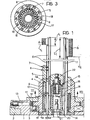
- reference numeral 1 indicates an annular element for supporting a rolling-element bearing 3, this element being fixed to a plate 2 which can be a fixed plate (if the device is constituted by a single insertion tool) or form part of a rotatable table (if the device forms part of a multiple-tool insertion machine).
- the rolling-element bearing 3 supports a guide bush 4 for rotation about its axis.
- the wedge-guide blades 6 are fixed to the slidable bush 5 by screws 7 and a reference pin 8.
- each spring 9 is interposed between the blind end of the associated hole 5a and an inner annular flange 4a with which the bush 4 is provided at its lower end.
- the lower ends of guide pins 10 are fixed to the flange 4a, each pin being inserted within a respective spring 9 and a respective hole 5a.
- the bush 4 is maintained in a fixed axial position by a ring 11 and is formed with an outer annular flange provided on its periphery with a reference notch 12 intended to cooperate with a reference member 13 resiliently urged against it in such a way as to allow the correct angular positioning of the bush 4.
- a cylindrical blade carrier 16 is keyed and axially fixed to the inner bush 14a by means of a resilient ring 15.
- the cylindrical blade carrier 16 has on its outer surface, in a manner known perse, a series of longitudinal grooves in which the coil-guide blades 17 are received and retained by means of pins 18.
- the annular series of coil-guide blades 17 is surrounded by the annular series of wedge-guide blades 6.
- Each wedge-guide blade 6 is disposed adjacent the outer face of an associated coil-guide blade.
- the said outer face of each coil-guide blade has, in a known way, longitudinal grooves in which the respective wedge-guide blade is slidably mounted. This latter has, also in a known way, two sides having each a groove for guiding an associated wedge.
- the annular flange 14 of the bush 14a is provided in a known manner on its periphery with two or more coupling slots 19 for coupling an indexing head operable to control the rotation of the unit supported rotatably by the bearing 3. This has the purpose of allowing the correct positioning of the various coils in the stator slots.
- the flange 14 further has an annular series of axial through slots for guiding the wedges.
- the bush 14 a is further provided internally and adjacent its lower end with a bush 20 for guiding a rod 21 intended to control the vertical movement of a thrust member 22, of a type known per se, which is slidably mounted within the annular series of coild-guide blades 17 and which is intended to effect the insertion of the coils into the stator.
- the rod 21 has an upper end which is connectable to the thrust member by means of a ball catch which is not described below, since it is of known type and does not fall within the scope of the present invention.
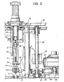
- the insertion rod 21 is fixed at its lower end to an insertion carriage 23. Also connected to this insertion carriage 23 is a support 24 to which is fixed a series of wedge-thrusting rods 28 intended to effect insertion of the wedges into the stator slots.
- the support 24 has two lower pins 25 slidably mounted within two bushes 26 carried by the insertion carriage 23.
- One of the pins 25 is locked in a fixed axial position relative to the insertion carriage 23 by means of a grooved wedge 27 control - led by a fluid cylinder (not illustrated).
- a helical spring 31 is interposed between an annular shoulder of the rod 21 and the support 24 and serves to urge the support 24 downwardly, causing the pins 25 to slide within the bushes 26 as soon as the wedge 27 is released. Following this release, the lower ends of the pins 25 come into contact with the two stop members 32.
- the vertical displacement of the insertion carriage 23 is controlled by a recirculating ball screw 33 engaged within a lead nut 34 forming part of the insertion carriage 23.
- This latter also includes a central structure slidably mounted with the interposition of bushes 36 on a guide column 35.
- the rotation of the screw 33 ist controlled by a d.c. motor 37 via a toothed belt transmission including a pair of pulleys 38, 39 and a toothed belt 40.
- the screw 33 is supported at its ends by bearing supports 41, 42 which ensure its rigidity.
- the wedge store (indicated with the reference numeral 29) is also illustrated in Fig. 2.
- This store is of a type known per se and has on its periphery a series of longitudinal grooves in which the wedges 30 intended to be inserted into the stator slots are received.
- the device When the relative position between the coil-guide blades and the wedge-guide blades is as illustrated in the left half of Fig. 1, the device is ready to operate on stators of minimum length.
- the stator (indicated A) is disposed around the coil-guide blades 17 and rests on the free ends of the wedge-guide blades 6.
- the motor 36 drives the screw 33 in such a way as to cause the insertion carriage 23 to rise.
- the surface of the carriage 23 (indicated X in Fig. 2) is thus carried to the level X"
- the carriage 23 axially moves the insertion rod 21 which effects insertion of the pre-wound coils into the stator slots.
- pre-wound coils are disposed on the coil-guide blades before insertion into the stator in such a way that, when the thrust member 22 rises within the coil-blade guides, it causes the coils to slide with respect to the coil-guide blades until they are inserted into the interior of the stator slots.
- the insertion carriage 23 acting via the support 24 and the pins 25 causes the wedge-thrusting rods 28 to rise.
- the wedge-thrusting rods 28 press the wedges 30 through the magazine 29 and through the spaces lying between the wedge-guide blades in such a way that when the carriage 23 has reached the said point X, the upper part of the wedge-thrusting rods 28 has reached the point indicated Y, in the left part of Fig. 1.
- the wedges 30 (of length L) are thus introduced into the slots of the stator A.
Landscapes
- Engineering & Computer Science (AREA)
- Manufacturing & Machinery (AREA)
- Power Engineering (AREA)
- Manufacture Of Motors, Generators (AREA)
Claims (10)
dadurch gekennzeichnet, dass die Keil-Führungszungen (6) gegen die Wirkung von Federmitteln (9) in die ihren freien Enden entgegengesetzte Richtung axial verschiebbar ist.
Applications Claiming Priority (2)
| Application Number | Priority Date | Filing Date | Title |
|---|---|---|---|
| IT6826182 | 1982-10-28 | ||
| IT68261/82A IT1156100B (it) | 1982-10-28 | 1982-10-28 | Dispositivo per l inserimento di matasse prevvolte nelle cave di statori di macchine dinamoelettriche atto ad operare su statori di altezza qualsiasi avente mezzi per l adeguamento automatico ad ogni altezza |
Publications (2)
| Publication Number | Publication Date |
|---|---|
| EP0110837A1 EP0110837A1 (de) | 1984-06-13 |
| EP0110837B1 true EP0110837B1 (de) | 1986-03-12 |
Family
ID=11308739
Family Applications (1)
| Application Number | Title | Priority Date | Filing Date |
|---|---|---|---|
| EP83830208A Expired EP0110837B1 (de) | 1982-10-28 | 1983-10-24 | Einsteckanlage für vorgewickelte Spulen zum Gebrauch bei der Fertigung von dynamoelektrischen Maschinen |
Country Status (5)
| Country | Link |
|---|---|
| US (1) | US4521958A (de) |
| EP (1) | EP0110837B1 (de) |
| JP (1) | JPS59103550A (de) |
| DE (1) | DE3362560D1 (de) |
| IT (1) | IT1156100B (de) |
Families Citing this family (3)
| Publication number | Priority date | Publication date | Assignee | Title |
|---|---|---|---|---|
| JPH0744807B2 (ja) * | 1990-11-26 | 1995-05-15 | 三工機器株式会社 | 単一駆動機構を有するコイル挿入機 |
| DE19708089A1 (de) * | 1997-01-24 | 1998-10-15 | Elmotec Elektro Motoren Tech | Verfahren und Vorrichtung zum Einziehen von Spulen in Nuten von Statorblechpaketen elektrischer Maschinen |
| DE19902198C2 (de) * | 1999-01-21 | 2001-02-22 | Elmotec Elektro Motoren Tech | Verfahren und Vorrichtung zum axialen Einziehen von Spulen in Statoren oder Rotoren elektrischer Maschinen |
Family Cites Families (10)
| Publication number | Priority date | Publication date | Assignee | Title |
|---|---|---|---|---|
| GB644761A (en) * | 1947-10-10 | 1950-10-18 | Gen Motors Corp | Improved apparatus for the manufacture of armatures for dynamo-electric machines |
| FR2203206B1 (de) * | 1972-03-21 | 1979-03-16 | Gen Electric | |
| FR2203205B1 (de) * | 1972-03-21 | 1976-10-29 | Gen Electric | |
| US3888638A (en) * | 1974-02-28 | 1975-06-10 | Industra Products | Insulating wedge insertion |
| DE2612904A1 (de) * | 1975-03-28 | 1976-10-07 | Gen Electric | Vorrichtung zum anordnen von spulen und verfahren zum einrichten der vorrichtung fuer das anordnen von spulen in kernen mit verschiedenen axialen laengen |
| US3968556A (en) * | 1975-11-07 | 1976-07-13 | Essex International, Inc. | Wedge feeding mechanism for short stroke dynamoelectric machine coil and wedge inserting apparatus |
| US4097989A (en) * | 1977-05-25 | 1978-07-04 | Essex Group, Inc. | Dynamoelectric machine coil inserting apparatus |
| GB1599353A (en) * | 1977-06-13 | 1981-09-30 | Gen Electric | Stator assemblies for dynamoelectric machines |
| US4156964A (en) * | 1978-03-23 | 1979-06-05 | Industra Products, Inc. | Coil placing machine with stack height adjustment |
| US4480379A (en) * | 1983-04-28 | 1984-11-06 | Industra Products, Inc. | Stack height adjustment for coil placing machines |
-
1982
- 1982-10-28 IT IT68261/82A patent/IT1156100B/it active
-
1983
- 1983-10-24 DE DE8383830208T patent/DE3362560D1/de not_active Expired
- 1983-10-24 EP EP83830208A patent/EP0110837B1/de not_active Expired
- 1983-10-28 JP JP58203581A patent/JPS59103550A/ja active Pending
- 1983-10-28 US US06/546,358 patent/US4521958A/en not_active Expired - Lifetime
Also Published As
| Publication number | Publication date |
|---|---|
| IT8268261A0 (it) | 1982-10-28 |
| EP0110837A1 (de) | 1984-06-13 |
| IT1156100B (it) | 1987-01-28 |
| DE3362560D1 (en) | 1986-04-17 |
| JPS59103550A (ja) | 1984-06-15 |
| US4521958A (en) | 1985-06-11 |
Similar Documents
| Publication | Publication Date | Title |
|---|---|---|
| US4449289A (en) | Automatic system and method for compressing coil turns and inserting insulators in slots of a slotted stator core | |
| US3698063A (en) | Apparatus for inserting coil side turn portions and insulators into the slots of a magnetic core | |
| US4223579A (en) | Machine tool | |
| US5207745A (en) | Methods and apparatus for automated stator winding station set up | |
| CA1091431A (en) | Method for drawing in of windings in grooves of stator packages and armatures in electro motors and an apparatus for the carrying out of the method | |
| EP0555323B1 (de) | Keileneinschiebvorrichtung mit keilenzwischenhalterung | |
| US4521958A (en) | Pre-wound coils inserting device for use in the manufacture of dynamo-electric machines | |
| US4347657A (en) | Method for the insertion of pre-wound coils into stator slots | |
| US4616788A (en) | Method and apparatus for winding dynamoelectric devices | |
| EP0052852A1 (de) | Einziehvorrichtung von Spulen | |
| US4003116A (en) | Apparatus for setting insulators and pressing end turns | |
| US4480379A (en) | Stack height adjustment for coil placing machines | |
| US4594771A (en) | Apparatus and method for automatically inserting coils and wedges into a stator core of any given length | |
| US4449293A (en) | Coil winding and inserting machine | |
| US4051595A (en) | Methods for setting insulators and pressing end turns | |
| US5647405A (en) | Device for winding coils for electrical machines | |
| DE3138495C2 (de) | Vorrichtung zum Einsetzen von Spulen in die Nuten eines Blechpaketes | |
| GB2115447A (en) | Winding wire coils in electromagnetic members | |
| EP0083827A1 (de) | Maschine zum Wickeln und Einziehen von Spulen | |
| US3626432A (en) | Tilt top tooling plate for coil assembly machines | |
| US5895004A (en) | Coil winding apparatus for large diameter magnetic rings | |
| US4160316A (en) | Apparatus for positioning insulating members in magnetic core slots | |
| CN214400955U (zh) | 自动化缝纫机换梭定位机构 | |
| US4557042A (en) | Automatic system for compressing coil turns and inserting insulators in slots of a slotted stator core | |
| US4285119A (en) | Methods and apparatus for use in producing wound coils and placing such coils on magnetic cores |
Legal Events
| Date | Code | Title | Description |
|---|---|---|---|
| PUAI | Public reference made under article 153(3) epc to a published international application that has entered the european phase |
Free format text: ORIGINAL CODE: 0009012 |
|
| AK | Designated contracting states |
Designated state(s): DE FR GB IT |
|
| 17P | Request for examination filed |
Effective date: 19840522 |
|
| GRAA | (expected) grant |
Free format text: ORIGINAL CODE: 0009210 |
|
| AK | Designated contracting states |
Kind code of ref document: B1 Designated state(s): DE FR GB IT |
|
| ITF | It: translation for a ep patent filed | ||
| REF | Corresponds to: |
Ref document number: 3362560 Country of ref document: DE Date of ref document: 19860417 |
|
| ET | Fr: translation filed | ||
| PLBE | No opposition filed within time limit |
Free format text: ORIGINAL CODE: 0009261 |
|
| STAA | Information on the status of an ep patent application or granted ep patent |
Free format text: STATUS: NO OPPOSITION FILED WITHIN TIME LIMIT |
|
| 26N | No opposition filed | ||
| ITPR | It: changes in ownership of a european patent |
Owner name: FUSIONI;PAVESI S.R.L. |
|
| REG | Reference to a national code |
Ref country code: GB Ref legal event code: 732 |
|
| REG | Reference to a national code |
Ref country code: FR Ref legal event code: TP Ref country code: FR Ref legal event code: CD |
|
| ITTA | It: last paid annual fee | ||
| ITPR | It: changes in ownership of a european patent |
Owner name: CESSIONE;AXIS S.P.A. |
|
| REG | Reference to a national code |
Ref country code: GB Ref legal event code: 732E |
|
| REG | Reference to a national code |
Ref country code: FR Ref legal event code: TP |
|
| PGFP | Annual fee paid to national office [announced via postgrant information from national office to epo] |
Ref country code: FR Payment date: 20011017 Year of fee payment: 19 |
|
| PGFP | Annual fee paid to national office [announced via postgrant information from national office to epo] |
Ref country code: DE Payment date: 20011227 Year of fee payment: 19 |
|
| REG | Reference to a national code |
Ref country code: GB Ref legal event code: IF02 |
|
| PGFP | Annual fee paid to national office [announced via postgrant information from national office to epo] |
Ref country code: GB Payment date: 20021004 Year of fee payment: 20 |
|
| PG25 | Lapsed in a contracting state [announced via postgrant information from national office to epo] |
Ref country code: DE Free format text: LAPSE BECAUSE OF NON-PAYMENT OF DUE FEES Effective date: 20030501 |
|
| PG25 | Lapsed in a contracting state [announced via postgrant information from national office to epo] |
Ref country code: FR Free format text: LAPSE BECAUSE OF NON-PAYMENT OF DUE FEES Effective date: 20030630 |
|
| REG | Reference to a national code |
Ref country code: FR Ref legal event code: ST |
|
| PG25 | Lapsed in a contracting state [announced via postgrant information from national office to epo] |
Ref country code: GB Free format text: LAPSE BECAUSE OF EXPIRATION OF PROTECTION Effective date: 20031023 |
|
| REG | Reference to a national code |
Ref country code: GB Ref legal event code: PE20 |