EP0110913B1 - Künstliche insel oder arbeitsplattform - Google Patents
Künstliche insel oder arbeitsplattform Download PDFInfo
- Publication number
- EP0110913B1 EP0110913B1 EP19830901638 EP83901638A EP0110913B1 EP 0110913 B1 EP0110913 B1 EP 0110913B1 EP 19830901638 EP19830901638 EP 19830901638 EP 83901638 A EP83901638 A EP 83901638A EP 0110913 B1 EP0110913 B1 EP 0110913B1
- Authority
- EP
- European Patent Office
- Prior art keywords
- toothing
- column
- pontoon
- work platform
- recesses
- Prior art date
- Legal status (The legal status is an assumption and is not a legal conclusion. Google has not performed a legal analysis and makes no representation as to the accuracy of the status listed.)
- Expired
Links
Images



Classifications
-
- E—FIXED CONSTRUCTIONS
- E02—HYDRAULIC ENGINEERING; FOUNDATIONS; SOIL SHIFTING
- E02B—HYDRAULIC ENGINEERING
- E02B17/00—Artificial islands mounted on piles or like supports, e.g. platforms on raisable legs or offshore constructions; Construction methods therefor
- E02B17/04—Equipment specially adapted for raising, lowering, or immobilising the working platform relative to the supporting construction
- E02B17/08—Equipment specially adapted for raising, lowering, or immobilising the working platform relative to the supporting construction for raising or lowering
- E02B17/0836—Equipment specially adapted for raising, lowering, or immobilising the working platform relative to the supporting construction for raising or lowering with climbing jacks
- E02B17/0872—Equipment specially adapted for raising, lowering, or immobilising the working platform relative to the supporting construction for raising or lowering with climbing jacks with locking pins engaging holes or cam surfaces
Definitions
- the invention relates to an artificial island or work platform comprising a pontoon or work floor and at least three columns displaceable in vertical direction in relation to the pontoon or work floor and attachable thereto, wherein at least one of said columns has in essence a multiangular horizontal cross section and comprises a toothing on at least one vertical longitudinal corner member, cooperating with locking beams of a clutching and clamping mechanism mounted onto the pontoon or work floor, which locking beams are moveable into and out of the openings between the teeth of said toothing, and comprising furthermore an elevating mechanism acting in vertical direction in conjunction with the clutching and clamping mechanism.
- the columns comprise outwards extending gear racks positioned in alignment with two opposed side walls and said gear racks are cooperating two by two with locking beams extending over more than the whole width of the other side walls and therefore having a length which is larger than the distance between two gear racks extending into the same direction.
- Said locking beams have to withstand large bending moments. These bending moments are increasing as the dimensions of said columns in the horizontal plane are increasing. This enlarges of course the weight of said locking beams and the dimensions of the tooth-openings in the gear racks.
- Said tooth-openings are formed an additional resistive factor for waves, wind and currents, increasing as said tooth-openings are larger and therefore extending further outside the profile of the column.
- the columns are extending through rectangular openings in the pontoon or work platform and the side walls of said openings have guiding means for said columns.
- the guiding means are cooperating with the side walls of the columns such that when the gear rack dimensions are increasing said guiding means should bridge a greater distance to correctly guide said columns.
- the purpose of the invention is now to provide an artificial island or work platform having a simple, strong and properly guideable construction as a whole also with larger column dimensions.
- the tooth-openings are therefore not embodied as recesses into strips extending outside the column profile, but by openings into the column angle profiles, which principle has wide spreading consequences for the complete construction.
- the openings into the pontoon or platform can have side walls which are very close to the side walls of the columns so that the dimensions of the guiding elements can be reduced si q nificantl y and the loads between the pontoon and the column can be transferred in a more favourable way.
- Still long beams can be used as locking beams meshing with extending parts into said openings, however said beams can be guided in such a way that the connecting section between both ends of said beam is not or not in a significant way loaded by bending moments.
- short locking beams are used which are displaceable into and out of the openings in the direction of the bisector of the inner angle of the profile and special preference is given to locking beams which are displaceable into or out of the toothing rotating around a vertical axis.
- the locking beams, meshing into a toothing opening of a longitudinal profile are supported very close to the edges of said opening into the frame work surrounding the column, the bending load onto said locking beams is very small so that said locking beams can have a significantly smaller thickness and also the height of the tooth opening can be respectively small.
- angle profiles comprising the series of openings or recesses forming the toothing, are beyond said openings on their inner surfaces mutually connected by means of a plate positioned transverse to the bisector of the inner angle of said profile.
- Said plate is strengthening the profile near the recesses and is closing and sealing off the column in the case where it is desirable to use a closed tubular profile for said column.
- the principle according to the invention can be applicated to columns of the closed type and columns of the open type.
- Columns of the closed types have completely closed side walls made out of plates.
- the wall thickness of the plates between the angle profiles can be thinner than the thickness of the angle profiles.
- Figure 1 illustrates the deck 1 of a pontoon 2.
- a column 3 is illustrated surrounded by a clutching and holding mechanism.
- the clutching and holding mechanism comprises a frame 4 with beams 5 which are rotatable round a vertical pinion 6 and they are each combined with an operating cylinder 7.
- the beams are positioned at each corner of the column 3 and are meshing into recesses 8, made into the longitudinal corner members 9 of each column. Therefore each of the four longitudinal members has a series of recesses 8.
- the frame 4 is installed at a fixed position onto the deck of the pontoon.
- a second frame 14 is installed comprising beams 15 rotatable around vertical pivot shafts 16 and operated by cylinders 17. These beams are illustrated in the resting position in Figure 2 whereas the working position is indicated by means of dash and dot lines.
- the frames 4 and 14 have in a way which is comparable to the columns a series of recesses or openings 18 in the corners of the frames and the edges of said openings 18 are used as supporting surfaces for the activated beams.
- the frames 4 and 14 are interconnected by means of a number of cylinders 20 so that in a generally known way the relative mutual displacement between columns and pontoon or platform can be realised.
- the angle profiles forming the longitudinal corner members 9 have at the inner side connecting plates 23, positioned perpendicular to the bisector of the inside angle of the profile.
- said plates are also functioning for closing and sealing the column.
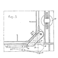
- Figure 3 differs from the embodiment of Figures 1 and 2 in the location of the cylinder 24, and especially the point of attachment 25 to the lock beam 26 which, as in the previous example, is rotatable around a vertical pivot shaft 27.
- Figure 3 illustrates the lock beam, installed at each corner, in the activated position and with dash and dot lines in the resting position. In the activated position the lock beam is, dependent on the working situation, in contact with the upper or lower surface of the recess indicated with 28 and 29, as well as with the lower and upper surface 30 and 31 of the corresponding recess in the frame 4 or 14.
- a guiding construction embodied as a number of ribs 32 is indicated in Figure 2.
- Figure 4 illustrates a corner detail in the throughgoing opening of the pontoon showing a longitudinal profile 9 of a column inside the corner 33 comprising the guiding strips 34 and 35 which are mutually connected by means of supporting strips 36 and are welded to the inner walls 37 and 38 of the opening in the pontoon. In this way a low tolerance guiding is possible.
- Figure 5 illustrates schematically a column 40 in a frame 41 which frame can support the clutching and locking means or the elevating mechanism.
- the locking mechanism comprises a long beam 42 extending along the side wall of the column and comprising at the ends the locking blocks 43, 44 extending into the openings 45 and 46 of the profiles 47, which profiles are forming the longitudinal corner members.
- Said locking beams 42, 43, 44 which are installed at both sides of the column in each frame, can be guided into openings of the profile or plate sections of the frame so that the connecting beam 42 inbetween the locking blocks 43 and 44 is not influenced by a bending load.
- the operation can be realised either by means of two cylinders, one for each block 43 respectively 44, or by means of one cylinder, coupled to the center part of the connecting beam 42.
- Figure 6 illustrates schematically a further embodiment in the form of a locking girder 48 installed at each corner, which locking girder 48 is displaceable from the non resting position indicated by the dash and dot lines to the active position indicated by full lines and is thereby moving in the direction of the bisector 49.
- Said displacement can be realised by means of one single cylinder acting into the direction of the bisector onto the center of the girder 48, whereby the correct position is reached when the girder comes into contact with the edges 50, 51 of the opening 52.
Landscapes
- Engineering & Computer Science (AREA)
- General Engineering & Computer Science (AREA)
- Mechanical Engineering (AREA)
- Civil Engineering (AREA)
- Structural Engineering (AREA)
- Bridges Or Land Bridges (AREA)
Claims (4)
Applications Claiming Priority (2)
| Application Number | Priority Date | Filing Date | Title |
|---|---|---|---|
| NL8202077A NL8202077A (nl) | 1982-05-19 | 1982-05-19 | Kunstmatig eiland of werkplatform. |
| NL8202077 | 1982-05-19 |
Publications (2)
| Publication Number | Publication Date |
|---|---|
| EP0110913A1 EP0110913A1 (de) | 1984-06-20 |
| EP0110913B1 true EP0110913B1 (de) | 1985-11-13 |
Family
ID=19839761
Family Applications (1)
| Application Number | Title | Priority Date | Filing Date |
|---|---|---|---|
| EP19830901638 Expired EP0110913B1 (de) | 1982-05-19 | 1983-05-19 | Künstliche insel oder arbeitsplattform |
Country Status (4)
| Country | Link |
|---|---|
| EP (1) | EP0110913B1 (de) |
| JP (1) | JPS59500875A (de) |
| NL (1) | NL8202077A (de) |
| WO (1) | WO1983004061A1 (de) |
Families Citing this family (3)
| Publication number | Priority date | Publication date | Assignee | Title |
|---|---|---|---|---|
| WO2005061802A1 (en) * | 2003-12-22 | 2005-07-07 | Innovative Solution Developers Bv | Drive assembly |
| CN110004887B (zh) * | 2019-02-28 | 2024-06-04 | 中电建(洛阳)装配式建筑科技有限公司 | 一种锁定梁开合装置及锁定梁开合方法 |
| CN109914356B (zh) * | 2019-04-09 | 2024-06-04 | 中电建(洛阳)装配式建筑科技有限公司 | 一种闸门锁定梁锁定装置及闸门锁定方法 |
Family Cites Families (2)
| Publication number | Priority date | Publication date | Assignee | Title |
|---|---|---|---|---|
| NL138827B (nl) * | 1966-01-10 | 1973-05-15 | Gusto Fa Nv | Inrichting voor het door middel van hydraulische druk teweegbrengen van een relatieve lineaire verplaatsing tussen een aantal kolommen en een hierlangs beweegbaar lichaam, zoals een ponton. |
| NL167487C (nl) * | 1970-08-18 | 1981-12-16 | Ihc Holland Nv | Inrichting voor het teweegbrengen van een relatieve lineaire verplaatsing tussen een aantal kolommen en een hierlangs beweegbaar lichaam. |
-
1982
- 1982-05-19 NL NL8202077A patent/NL8202077A/nl not_active Application Discontinuation
-
1983
- 1983-05-19 WO PCT/NL1983/000021 patent/WO1983004061A1/en not_active Ceased
- 1983-05-19 EP EP19830901638 patent/EP0110913B1/de not_active Expired
- 1983-05-19 JP JP58501752A patent/JPS59500875A/ja active Pending
Also Published As
| Publication number | Publication date |
|---|---|
| JPS59500875A (ja) | 1984-05-17 |
| NL8202077A (nl) | 1983-12-16 |
| EP0110913A1 (de) | 1984-06-20 |
| WO1983004061A1 (en) | 1983-11-24 |
Similar Documents
| Publication | Publication Date | Title |
|---|---|---|
| US5755982A (en) | Concrete casting system | |
| US3797952A (en) | Roadway transition for expansion joints on road bridges etc. | |
| US3889779A (en) | Length adjustable plank | |
| DE102012102808A1 (de) | Kran, insbesondere Brückenkran oder Portalkran, mit mindestens einem Kranträger | |
| US8276874B2 (en) | Ceiling formwork system | |
| DE3025990A1 (de) | Waage | |
| EP0585971B1 (de) | Brückenelement | |
| DE102012102809A1 (de) | Kran, insbesondere Brückenkran oder Portalkran, mit mindestens einem Kranträger | |
| EP3857002B1 (de) | Stützenkopf, deckenstütze, deckenschalung und verfahren zum errichten einer solchen deckenschalung | |
| DE2310235A1 (de) | Vorrichtung zum heben und senken von schweren lasten | |
| US4171550A (en) | Loading system | |
| WO1983004061A1 (en) | Artificial island or work platform | |
| DE3219456C2 (de) | ||
| US5180256A (en) | Support device for lining a ditch | |
| EP3253707A1 (de) | Kran, insbesondere brückenkran oder portalkran, mit mindestens einem kranträger | |
| DE4303727A1 (de) | ||
| DE4316203A1 (de) | Bausatz zum Erstellen eines Bahnsteiges in Fertigteilbauweise | |
| DE3409452A1 (de) | Verstellbare schalung fuer betonbauteile | |
| US3901472A (en) | Adjustable apparatus for sliding form construction | |
| US4441838A (en) | Element for tunnel-type metal shuttering | |
| GB2149874A (en) | Building structure | |
| DE1549244B2 (de) | Vorrichtung zum Wiegen einer über einen Schienenstrang rottenden Last | |
| DE2658020B2 (de) | Auf Stützen aufgelagerte Stahlbetondecke | |
| DE2903785C3 (de) | Brückenauflager am Kopf einer Spundwand | |
| EP1121232B1 (de) | Verfahren und Vorrichtung zur Herstellung von Wandelementen |
Legal Events
| Date | Code | Title | Description |
|---|---|---|---|
| PUAI | Public reference made under article 153(3) epc to a published international application that has entered the european phase |
Free format text: ORIGINAL CODE: 0009012 |
|
| 17P | Request for examination filed |
Effective date: 19840116 |
|
| AK | Designated contracting states |
Designated state(s): FR GB NL |
|
| GRAA | (expected) grant |
Free format text: ORIGINAL CODE: 0009210 |
|
| AK | Designated contracting states |
Designated state(s): FR GB NL |
|
| PG25 | Lapsed in a contracting state [announced via postgrant information from national office to epo] |
Ref country code: FR Free format text: THE PATENT HAS BEEN ANNULLED BY A DECISION OF A NATIONAL AUTHORITY Effective date: 19851113 |
|
| EN | Fr: translation not filed | ||
| PLBE | No opposition filed within time limit |
Free format text: ORIGINAL CODE: 0009261 |
|
| STAA | Information on the status of an ep patent application or granted ep patent |
Free format text: STATUS: NO OPPOSITION FILED WITHIN TIME LIMIT |
|
| 26N | No opposition filed | ||
| PGFP | Annual fee paid to national office [announced via postgrant information from national office to epo] |
Ref country code: NL Payment date: 19870531 Year of fee payment: 5 |
|
| GBPC | Gb: european patent ceased through non-payment of renewal fee | ||
| PG25 | Lapsed in a contracting state [announced via postgrant information from national office to epo] |
Ref country code: GB Free format text: LAPSE BECAUSE OF NON-PAYMENT OF DUE FEES Effective date: 19881122 |
|
| PG25 | Lapsed in a contracting state [announced via postgrant information from national office to epo] |
Ref country code: NL Effective date: 19881201 |
|
| NLV4 | Nl: lapsed or anulled due to non-payment of the annual fee |