EP0110923B1 - Dispositif de lecture et de stockage d'informations optiques sur un support plan - Google Patents
Dispositif de lecture et de stockage d'informations optiques sur un support plan Download PDFInfo
- Publication number
- EP0110923B1 EP0110923B1 EP83901708A EP83901708A EP0110923B1 EP 0110923 B1 EP0110923 B1 EP 0110923B1 EP 83901708 A EP83901708 A EP 83901708A EP 83901708 A EP83901708 A EP 83901708A EP 0110923 B1 EP0110923 B1 EP 0110923B1
- Authority
- EP
- European Patent Office
- Prior art keywords
- scanner
- copy
- scanning
- memory
- line
- Prior art date
- Legal status (The legal status is an assumption and is not a legal conclusion. Google has not performed a legal analysis and makes no representation as to the accuracy of the status listed.)
- Expired
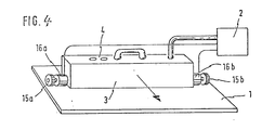
Links
Images


Classifications
-
- G—PHYSICS
- G06—COMPUTING OR CALCULATING; COUNTING
- G06K—GRAPHICAL DATA READING; PRESENTATION OF DATA; RECORD CARRIERS; HANDLING RECORD CARRIERS
- G06K7/00—Methods or arrangements for sensing record carriers, e.g. for reading patterns
- G06K7/10—Methods or arrangements for sensing record carriers, e.g. for reading patterns by electromagnetic radiation, e.g. optical sensing; by corpuscular radiation
- G06K7/10544—Methods or arrangements for sensing record carriers, e.g. for reading patterns by electromagnetic radiation, e.g. optical sensing; by corpuscular radiation by scanning of the records by radiation in the optical part of the electromagnetic spectrum
- G06K7/10821—Methods or arrangements for sensing record carriers, e.g. for reading patterns by electromagnetic radiation, e.g. optical sensing; by corpuscular radiation by scanning of the records by radiation in the optical part of the electromagnetic spectrum further details of bar or optical code scanning devices
- G06K7/10881—Methods or arrangements for sensing record carriers, e.g. for reading patterns by electromagnetic radiation, e.g. optical sensing; by corpuscular radiation by scanning of the records by radiation in the optical part of the electromagnetic spectrum further details of bar or optical code scanning devices constructional details of hand-held scanners
-
- H—ELECTRICITY
- H04—ELECTRIC COMMUNICATION TECHNIQUE
- H04N—PICTORIAL COMMUNICATION, e.g. TELEVISION
- H04N1/00—Scanning, transmission or reproduction of documents or the like, e.g. facsimile transmission; Details thereof
- H04N1/04—Scanning arrangements, i.e. arrangements for the displacement of active reading or reproducing elements relative to the original or reproducing medium, or vice versa
- H04N1/10—Scanning arrangements, i.e. arrangements for the displacement of active reading or reproducing elements relative to the original or reproducing medium, or vice versa using flat picture-bearing surfaces
- H04N1/107—Scanning arrangements, i.e. arrangements for the displacement of active reading or reproducing elements relative to the original or reproducing medium, or vice versa using flat picture-bearing surfaces with manual scanning
- H04N1/1072—Means for guiding the scanning, e.g. rules
-
- H—ELECTRICITY
- H04—ELECTRIC COMMUNICATION TECHNIQUE
- H04N—PICTORIAL COMMUNICATION, e.g. TELEVISION
- H04N2201/00—Indexing scheme relating to scanning, transmission or reproduction of documents or the like, and to details thereof
- H04N2201/04—Scanning arrangements
- H04N2201/047—Detection, control or error compensation of scanning velocity or position
- H04N2201/04701—Detection of scanning velocity or position
- H04N2201/0471—Detection of scanning velocity or position using dedicated detectors
-
- H—ELECTRICITY
- H04—ELECTRIC COMMUNICATION TECHNIQUE
- H04N—PICTORIAL COMMUNICATION, e.g. TELEVISION
- H04N2201/00—Indexing scheme relating to scanning, transmission or reproduction of documents or the like, and to details thereof
- H04N2201/04—Scanning arrangements
- H04N2201/047—Detection, control or error compensation of scanning velocity or position
- H04N2201/04701—Detection of scanning velocity or position
- H04N2201/04715—Detection of scanning velocity or position by detecting marks or the like, e.g. slits
- H04N2201/04724—Detection of scanning velocity or position by detecting marks or the like, e.g. slits on a separate encoder wheel
-
- H—ELECTRICITY
- H04—ELECTRIC COMMUNICATION TECHNIQUE
- H04N—PICTORIAL COMMUNICATION, e.g. TELEVISION
- H04N2201/00—Indexing scheme relating to scanning, transmission or reproduction of documents or the like, and to details thereof
- H04N2201/04—Scanning arrangements
- H04N2201/047—Detection, control or error compensation of scanning velocity or position
- H04N2201/04701—Detection of scanning velocity or position
- H04N2201/04715—Detection of scanning velocity or position by detecting marks or the like, e.g. slits
- H04N2201/04727—Detection of scanning velocity or position by detecting marks or the like, e.g. slits on a linear encoder
-
- H—ELECTRICITY
- H04—ELECTRIC COMMUNICATION TECHNIQUE
- H04N—PICTORIAL COMMUNICATION, e.g. TELEVISION
- H04N2201/00—Indexing scheme relating to scanning, transmission or reproduction of documents or the like, and to details thereof
- H04N2201/04—Scanning arrangements
- H04N2201/047—Detection, control or error compensation of scanning velocity or position
- H04N2201/04701—Detection of scanning velocity or position
- H04N2201/04734—Detecting at frequent intervals, e.g. once per line for sub-scan control
Definitions
- the invention relates to a device for producing optically or electronically or magnetically stored image information of an essentially flat original with the features of the preamble of the appended claim 1.
- the object of the invention is to be able to store optically or electronically or magnetically stored image information in accordance with an essentially flat template in such a way that neither special handling of the template nor particularly skillful handling of a scanning device is important, the effort required for photographic reproduction should also be avoided.
- At least one further signal generator is arranged on the scanning device and supplies control signals which report a non-uniform movement of the scanning device with respect to the original.
- the invention primarily implements a vacuum cleaner principle in the production of the optically or electronically or magnetically stored image information, according to which the information is sucked out of the template by hand using a suitable scanning device and is read into or stored in a storage device.
- a template In conventional copying processes, a template must either be placed on a platen in such a way that the information-containing surface of the template faces a scanning device, which is arranged within the device in question and is positively guided with respect to a scanning movement, or the template must be introduced into a feed device, which the Template passes a scanning device or scanning optics.
- the invention avoids these techniques in order to protect the original and to increase the ease of use of copying machines. This is particularly noticeable when making copies from thick books and large files.
- Devices of the type proposed here allow copying according to the vacuum cleaner principle already mentioned from files, without the need to file individual sheets in order to be able to copy the sheet format completely.
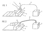
- a flat template is shown schematically and designated 1.
- the image information of this template is to be photoelectrically or optically or magnetically or electrically stored in storage means 2.
- Optical storage of the image information is present, for example, in a copy on a carrier material, for example on paper.
- Electronic storage can be carried out using a memory matrix made of semiconductor elements.
- Magnetic storage can be done on a magnetic disk or a magnetic tape.
- a scanning device 3 is used to scan or remove the image information from the template, which can be placed on the template 1 by hand and guided over the template in order to remove the image information from the template 1.
- Operating buttons 4 provided on the scanning device serve to switch on the entire device and to trigger the recording process.
- the image information taken from the original is transmitted from the scanning device 3 to the fixed storage means via an information transmission channel 5, which in the embodiment according to FIG. 1 has the form of a wireless radio transmission channel, such that in the scanning device 3 a transmitter and in place the storage means 2 are housed a receiver, which can have comparatively small power at the short distances between transmitter and receiver which are generally considered here.
- the wireless radio transmission channel 5 permits essentially any movement of the scanning device 3 relative to the storage means and any other devices, so that the scanning device designed as a handy unit can be moved to scan the original while the original remains in its original location and not in one Device, in particular a copying device, must be inserted, placed on it or handled in a similar manner.
- the information transmission channel which permits essentially any relative movement between the scanning device and the storage means has the form of a flexible high-frequency signal transmission cable 6, which leads from the scanning device 3 to the storage means 2.
- the design and mode of operation in the embodiment according to FIG. 2 are similar to those in the embodiment according to FIG. 1.
- the presence or absence of light pulses and the corresponding electrical signals are determined while the scanning device is being moved by hand over the original by means of a series of light-sensitive scanning elements corresponding to the image of the original.
- These signals are transmitted, for example, serially via the information transmission channel 5 or 6 to the storage means and stored there in a specific order.
- the storage order is determined on the one hand by the position of the individual scanning elements in a row next to one another in accordance with a line of the original to be scanned and by the scanning path of the scanning device over the original, wherein individual scanning elements are moved along a column of the original if a correspondingly precise guidance of the Scanning device 3 is reached.
- the scanning device 3 is not guided precisely in parallel by an operator, is not guided precisely at a constant speed and is possibly also shifted somewhat in the line direction, the recording of the image information made in the storage means is correspondingly distorted and requires an equalization in accordance with information which is also are transmitted via the information transmission channel 5 or 6 and which are collected by suitable measuring devices located on the scanning device 3, which respond to the movement of the scanning device 3. Details of this will be discussed in more detail below.
- the storage means 2 can be carried out very easily, which is particularly the case if these storage means do not have the form of an electrophotographic recording mechanism with a corona charging station, exposure station, toner development station and fixing station, but rather, for example, a magnet for the purpose of space-saving intermediate storage provide tape storage, the storage means can be carried on the scanning device 3, as is shown schematically in FIG. 3.
- the storage means have the form of a magnetic tape recording device with a magnetic tape cassette, which can be used, for example, in a handle part 7 of the scanning device and can be removed again. After the image information has been stored in the magnetic tape cassette of the storage means 2, the magnetic tape cassette is removed from the device 3 and inserted into a playback device in order to control the production of a reproduction of the image information therein.
- the scanning device 3 contains, in a scanning bar 8 extending across the width of the original 1, a multiplicity of optical fibers 9 extending in a plane next to one another and parallel to one another, the said plane being kept approximately normal to the plane of the original 1 in the use position of the device.
- An illuminating device can also be provided in the scanning device 3, which is designed approximately in the manner indicated schematically in FIG. 6 and which serves to illuminate the original surface in such a way that the downward-facing ends of the optical fibers 9 differ depending on the image information content of the original surface be exposed to light energy.
- the light guide fibers 9 lead to a transducer unit 10, in which light pulses can be removed from the ends of the light guide fibers lying away from the original surface and, for example, photosensitive switching means can be supplied, with one photosensitive switching element each being assigned to one optical fiber and capable of emitting corresponding electrical signals for each light pulse.
- optical fibers 9 of very small diameter, which are optically isolated from one another.
- the light guide fibers can be cast in a synthetic resin carrier or cemented between two carrier halves.
- a sufficient distance between the light guide ends lying away from the original surface such that the photosensitive switching elements to be coupled therewith find space next to one another can be achieved by fanning out the light guide ends or by grouping the length of the light guide fibers 9 in groups.
- the photosensitive switching elements can each be connected to an associated short-term storage element with their output providing the electrical signals, such that the electrical signals corresponding to the optical pulses of the photosensitive switching elements can be selected by a multiplexer 11 operating at high speed in a recurring sequence corresponding to the line progress and after amplification in an amplifier 12 can be registered serially in the magnetic tape recording device together with line advance signals entered in a suitable manner.
- a measuring device 13 is included in the scanning device 3, which forms measurement signals which correspond to the speed of movement of the device 3 across the original due to a corresponding manual operation by the operator or in the respective position of the scanning device 3 on the format of the original 1 correspond, for which a corresponding integration of speed measurement signals is necessary. If the measuring device 13 is only able to emit measurement signals corresponding to the acceleration, a two-time integration is necessary in order to obtain the position signals.
- the electrical signals corresponding to the scanning speed or the respective scanning position, which are taken from or derived from the output of the measuring device 13, are recorded on an additional track of the storage means 2 or on a separate memory, which can be taken from the device 3 together with the storage means 2 and is to be used in a reproduction device in order to control the reproduction of the temporarily stored image information with correction of any non-uniform scanning movements.
- the embodiment according to FIG. 3 is not comparable with mobile copying machines which operate manually via the Template can be carried away and which immediately provide a copy of the template, as by removing the buffer organ of the storage means from the scanning device 3 in the device proposed here and transporting it to a reproduction station, which is set up in a fixed location, the basic idea disclosed here is realized, by template scanning Image information regardless of the position of the scanning device in a stationary unit without evaluating the format limitation known from instant cameras, this unit not burdening the scanning device itself due to its space requirement and weight.
- the current position of the scanning device with respect to an initial position is to be recorded, and not only With reference to the line progress direction, but also with reference to a direction parallel to the individual line and at an angle to the template line, a measuring system with a so-called inertial platform is expediently arranged on the device according to FIG. 5, which is here two-dimensionally effective.
- inert masses 25 are held on beryllium bronze springs 24, which deform in the elastic range essentially without hysteresis, with respect to a deflection direction in the direction of line progress or parallel to the line direction.
- the inertial masses are opposed by proximity sensors 26, which respond capacitively or inductively to the distance to the inertial masses 25 and depending on a deflection of the inertial masses 25 on the leaf springs 24 relative to a housing part of the scanning device 3 and thus depending on the acceleration of the device 3 provide output signals to integrators 27 relative to template 1.
- the integrators 27 carry out a double integration of the acceleration signals in order to provide the respective current position of the scanning device 3 on the template 1 corresponding signals which are used in the storage means 2 to control the storage speed or the respective storage address for the image information signals which are via the information transmission channel 6 is passed on from the device 3 to the storage means 2.
- the acceleration sensors formed from the components 24 to 26 work with extraordinarily high precision and speed, whereby in the case of a capacitive proximity sensor 26 the capacitance to the inertial mass 25 serves to detune a precision resonant circuit, from the frequency of which the output signal can be derived.
- Fig. 6 shows an optical scanning head of the scanning device 3 with an arrangement at a short distance from each other parallel, lying in one plane optical fibers 9, which lead out of the parallel position in the region of the scanning nose in contrast to the device according to Fig. 3 not to optical-electrical Converters run, but are combined to form the flexible information transmission cable 6, as is shown in FIG. 6 by broken lines.
- the optical fibers are fanned out to an output scanning head in an order which corresponds to that in the scanning device 3.
- the ends of the optical fibers 9 located on the side of the storage means 2 serve to expose an electrographic recording material which is passed under these ends, optionally with the interposition of optics, and which has previously been guided past a corona charging station in a manner known per se and which after exposure has passed a toner development station and a fixing station or a transfer station for transferring the toner image onto a carrier, for example on paper, passes.
- optical fibers 9 which are optically isolated from one another, is embedded or cemented between two support halves 28 and 29, which are tapered downwards towards one another in the position of use, so that a scanning lug 30 is formed, in the tip of which the template 1 open ends of the optical fibers 9 open.
- a lighting chamber 31 which is closed at the top by a reflector profile 32 and which is provided on its inner walls with the exception of a slot opening towards template 1 with reflection coatings.
- a fluorescent tube 33 which is switched on during the scanning of the original 1 and which has the task of illuminating the original in the area adjacent to the lower ends of the optical fibers 9.
- the optical fibers 9 can be used both for the inward and for the return of the light, so that the optical fibers not only serve to derive the light reflected by the image information elements, but also to illuminate the original surface in certain areas .
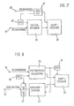
- FIG. 7 and 8 show embodiments of the evaluation devices at the location of the storage means for equalizing the image information recorded by the scanning devices 3, taking into account any incorrect movements of the scanning device.
- the image information transmitted via the flexible or wireless information transmission channel is fed at a terminal 34 to the input of a buffer memory 35, which in the embodiment according to FIG. 7 can be a short-term memory, while in the embodiment according to FIG. 8 it stores the image information over a longer period Time period can make.
- the signals of the aforementioned measuring device 13 which represent an instantaneous position of the scanning device 3 or corresponding signals derived from the tachometers 16a and 16b are supplied together with clock pulses from a clock generator 36 to an address generator 37 which is used for addressing a main memory 38.
- control signals input via the terminal 39 correspond to the respective position of the scanning device 3 in the address generator 37 such an address correction that when image information signals from the buffer memory 35 into the main memory 38 are transferred, the storage takes place in such places that an immediate assignment to the position of the image information on the surface of the template 1 is restored.
- the embodiment according to FIG. 8 differs from that according to FIG. 7 in that the corrected addresses output by the address generator 37 are not used directly for addressing the main memory 38, but are stored in an address memory 40, which is then clocked by another Clock 41 is read out simultaneously with the buffer memory 35 and is used for addressing the main memory 38, while the image information is read out from the buffer memory 35.
- This mode of operation of the system was previously indicated in connection with the description of the exemplary embodiment according to FIG. 3, insofar as this concerned information storage in an additional track of the magnetic tape cassette or in a parallel memory.
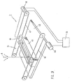
- the main memory according to FIGS. 7 and 8 or the aforementioned storage means may have the form shown in FIG. 9 and be formed by an electrophotographic recording system in which an electrophotographic recording material 43 is scanned by means of a recording system 44.
- the recording system effects a line-by-line exposure of the recording material 43 with progress from line to line, the image information signals in the form of electrical or optical pulses being supplied via the flexible or wireless information transmission channel 6. If electrical signals are involved, the recording system 44 converts them back into optical signals.
- a strip-like recording head 45 of the recording device 44 is fastened at its left and right ends to separately drivable wire cables 46 and 47 guided over rollers, in such a way that the strip-shaped scanning head 45 is relative to different angular positions by different loading of the drive motors 48 and 49 can be brought to the edges of the format of the recording material 43.
- a further drive 50 enables the active organs of the scanning head to be shifted to the side, so that a corresponding shifting of the motor 50 can result in a lateral shift of an entire scanning line.
- a control unit 51 can therefore, in the storage means 2, as a function of control signals which are supplied to the scanning device 3 by suitable measuring devices, correct the recording by the scanning head 45 on the recording material 34 in accordance with any incorrect movements of the scanning device 3 over the original 1. Should it become apparent that the control unit 51 and the measuring device of the scanning device feeding this, as well as the drive motors 48, 49 and 50 do not work sufficiently quickly and without inertia to prevent distortion of the image recording in the storage means 2, it may be expedient in that use flexible or wireless information transmission channel 6 or 5 delay means or buffer storage means.
- markers or catches on these templates themselves are not required in order to control the scanning process.
Landscapes
- Engineering & Computer Science (AREA)
- Physics & Mathematics (AREA)
- Multimedia (AREA)
- Signal Processing (AREA)
- Electromagnetism (AREA)
- General Health & Medical Sciences (AREA)
- Health & Medical Sciences (AREA)
- Toxicology (AREA)
- Artificial Intelligence (AREA)
- Computer Vision & Pattern Recognition (AREA)
- General Physics & Mathematics (AREA)
- Theoretical Computer Science (AREA)
- Facsimile Scanning Arrangements (AREA)
Abstract
Claims (8)
Applications Claiming Priority (2)
| Application Number | Priority Date | Filing Date | Title |
|---|---|---|---|
| DE3220016 | 1982-05-27 | ||
| DE19823220016 DE3220016A1 (de) | 1982-05-27 | 1982-05-27 | Einrichtung zur herstellung einer optisch bzw. elektronisch oder magnetisch gespeicherten bildinformation einer im wesentlichen flaechigen vorlage |
Publications (2)
| Publication Number | Publication Date |
|---|---|
| EP0110923A1 EP0110923A1 (fr) | 1984-06-20 |
| EP0110923B1 true EP0110923B1 (fr) | 1986-09-17 |
Family
ID=6164667
Family Applications (1)
| Application Number | Title | Priority Date | Filing Date |
|---|---|---|---|
| EP83901708A Expired EP0110923B1 (fr) | 1982-05-27 | 1983-05-27 | Dispositif de lecture et de stockage d'informations optiques sur un support plan |
Country Status (4)
| Country | Link |
|---|---|
| EP (1) | EP0110923B1 (fr) |
| JP (1) | JPS59500938A (fr) |
| DE (2) | DE3220016A1 (fr) |
| WO (1) | WO1983004160A2 (fr) |
Families Citing this family (14)
| Publication number | Priority date | Publication date | Assignee | Title |
|---|---|---|---|---|
| US4587568A (en) * | 1983-03-18 | 1986-05-06 | Oki Electric Industry Co., Ltd. | Electronic print board |
| US4684998A (en) * | 1983-06-15 | 1987-08-04 | Canon Kabushiki Kaisha | Image reader suitable for manual scanning |
| CA1213971A (fr) * | 1983-12-19 | 1986-11-12 | Sony Corporation | Dispositif d'introduction d'images en memoire |
| US4707747A (en) * | 1984-07-13 | 1987-11-17 | Rockwell Iii Marshall A | Hand held scanning input device and system |
| JPS61118058A (ja) * | 1984-11-14 | 1986-06-05 | Casio Comput Co Ltd | 携帯用リ−ダ・プリンタ装置 |
| JPH0727540B2 (ja) * | 1985-08-21 | 1995-03-29 | シャープ株式会社 | 手動掃引イメ−ジ読み取り装置 |
| EP0216304B1 (fr) * | 1985-09-21 | 1993-02-24 | Toyo Polymer Company Limited | Appareil de reproduction d'affichages |
| GB8604040D0 (en) * | 1986-02-19 | 1986-03-26 | Gilcrist Studios Group Ltd | Re-creating images |
| US4797544A (en) * | 1986-07-23 | 1989-01-10 | Montgomery James R | Optical scanner including position sensors |
| DE3723785A1 (de) * | 1987-07-16 | 1989-01-26 | Siemens Ag | Verfahren und vorrichtung zum optischen abtasten einer vorlage |
| DK159749C (da) * | 1987-11-24 | 1991-04-29 | Eskofot As | Fremgangsmaade til udvinding af digitale optegningsdata ved hjaelp af et skanderende halvlederkamera. |
| JPH01222564A (ja) * | 1988-03-01 | 1989-09-05 | Sony Corp | 手動走査型の画像入出力装置 |
| US5144120A (en) * | 1988-05-11 | 1992-09-01 | Symbol Technologies, Inc. | Mirrorless scanners with movable laser, optical and sensor components |
| JPH0787503B2 (ja) * | 1988-09-13 | 1995-09-20 | シャープ株式会社 | 画像読取装置を有する通信装置 |
Family Cites Families (10)
| Publication number | Priority date | Publication date | Assignee | Title |
|---|---|---|---|---|
| DE1080592B (de) * | 1958-12-19 | 1960-04-28 | Grundig Max | Verfahren und Einrichtung zur Fernuebertragung von Bewegungsvorgaengen in einer ebenen Flaeche |
| FR1601413A (fr) * | 1968-06-26 | 1970-08-24 | ||
| US3739095A (en) * | 1971-08-02 | 1973-06-12 | Alden Res Found | Scanning apparatus |
| DE2161038C3 (de) * | 1971-12-09 | 1985-06-20 | Dr.-Ing. Rudolf Hell Gmbh, 2300 Kiel | Verfahren zur Herstellung von gerasterten Druckformen |
| GB1446403A (en) * | 1974-09-13 | 1976-08-18 | Mullard Ltd | Scanning systems circuit block for an electronic watch |
| DE2552694A1 (de) * | 1975-11-25 | 1977-06-02 | Witec Wissenschaftlich Tech Be | System zur aufzeichnung und wiedergabe von informationen |
| GB2030824B (en) * | 1978-08-18 | 1982-10-13 | Konishiroku Photo Ind | Transmission-reception apparatus |
| DE2910854A1 (de) * | 1979-03-20 | 1980-10-02 | Agfa Gevaert Ag | Informationsverarbeitungsvorrichtung zur aufnahme und zur weiterverarbeitung von auf einem informationstraeger befindlicher optischer information |
| US4260979A (en) * | 1979-12-31 | 1981-04-07 | International Business Machines Corporation | Apparatus for sensing non-coded images |
| DE3014433A1 (de) * | 1980-04-15 | 1981-10-22 | Siemens AG, 1000 Berlin und 8000 München | Anordnung zum abtasten von mit graphischen mustern versehenen vorlagen |
-
1982
- 1982-05-27 DE DE19823220016 patent/DE3220016A1/de not_active Withdrawn
-
1983
- 1983-05-27 EP EP83901708A patent/EP0110923B1/fr not_active Expired
- 1983-05-27 JP JP58501813A patent/JPS59500938A/ja active Pending
- 1983-05-27 WO PCT/EP1983/000133 patent/WO1983004160A2/fr not_active Ceased
- 1983-05-27 DE DE8383901708T patent/DE3366232D1/de not_active Expired
Also Published As
| Publication number | Publication date |
|---|---|
| DE3220016A1 (de) | 1983-12-01 |
| EP0110923A1 (fr) | 1984-06-20 |
| JPS59500938A (ja) | 1984-05-24 |
| DE3366232D1 (en) | 1986-10-23 |
| WO1983004160A3 (fr) | 1983-12-22 |
| WO1983004160A2 (fr) | 1983-12-08 |
Similar Documents
| Publication | Publication Date | Title |
|---|---|---|
| DE3689454T2 (de) | Lichtabtastvorrichtung. | |
| DE3040921C2 (de) | Verfahren zum Betreiben eines Bildverarbeitungssystems | |
| DE69515712T2 (de) | Hochauflösender Filmabtaster | |
| DE69324096T2 (de) | Verfahren und Vorrichtung zum Drucken | |
| DE3536603C2 (fr) | ||
| DE3220016A1 (de) | Einrichtung zur herstellung einer optisch bzw. elektronisch oder magnetisch gespeicherten bildinformation einer im wesentlichen flaechigen vorlage | |
| DE3534338A1 (de) | Elektrofotografischer drucker mit einer belichtungsenergie/korrektureinrichtung fuer den optischen zeichengenerator | |
| DE19544178A1 (de) | Vorrichtung zum scannenden Digitalisieren von Bildvorlagen sowie Verfahren zu deren Betrieb | |
| DE2916305A1 (de) | Kopierverfahren und kopiergeraet | |
| DE3336961C2 (fr) | ||
| DE3687372T2 (de) | Abtastanordnung. | |
| DE2851177A1 (de) | Elektrostatisches kopiergeraet | |
| DE19680169C2 (de) | Bildeingabevorrichtung | |
| DE69122993T2 (de) | Ein- und Ausgangsabtaster | |
| DE2944602A1 (de) | Lichtstrahl-aufzeichnungsvorrichtung | |
| DE3783984T2 (de) | Kopierer mit positionskontrollierbarer subabtasteinrichtung. | |
| DE4016251C2 (fr) | ||
| DE2502921A1 (de) | Einrichtung und verfahren zum senden und empfangen von faksimile- signalen | |
| DE2944161C2 (de) | Vorrichtung zur Feststellung der Scharfeinstellung eines optischen Systems | |
| DE69124430T2 (de) | Abtaster mit Mitteln zur Registrierung von Vorlagen und Kopieblättern | |
| DE2301335C3 (de) | Faksimile-Verfahren mit abwechselnder Verwendung einer Endstation als Empfänger oder Sender | |
| DE2534720A1 (de) | Kombiniertes kopier- und fernkopiergeraet | |
| DE69213838T2 (de) | Dokumentenabtaster und -drucker mit einfacher Konstruktion für manuelle Blattzufuhr | |
| DE2518615C2 (de) | Kombiniertes Faksimile- und Kopiergerät | |
| DE69311649T3 (de) | Strahlsteuerungssensor für einen Rasterabtaster |
Legal Events
| Date | Code | Title | Description |
|---|---|---|---|
| PUAI | Public reference made under article 153(3) epc to a published international application that has entered the european phase |
Free format text: ORIGINAL CODE: 0009012 |
|
| AK | Designated contracting states |
Designated state(s): BE CH DE FR GB LI NL |
|
| 17P | Request for examination filed |
Effective date: 19840608 |
|
| GRAA | (expected) grant |
Free format text: ORIGINAL CODE: 0009210 |
|
| AK | Designated contracting states |
Kind code of ref document: B1 Designated state(s): DE FR GB NL SE |
|
| PG25 | Lapsed in a contracting state [announced via postgrant information from national office to epo] |
Ref country code: NL Effective date: 19860917 Ref country code: FR Free format text: THE PATENT HAS BEEN ANNULLED BY A DECISION OF A NATIONAL AUTHORITY Effective date: 19860917 |
|
| PG25 | Lapsed in a contracting state [announced via postgrant information from national office to epo] |
Ref country code: SE Effective date: 19860930 |
|
| REF | Corresponds to: |
Ref document number: 3366232 Country of ref document: DE Date of ref document: 19861023 |
|
| EN | Fr: translation not filed | ||
| NLV1 | Nl: lapsed or annulled due to failure to fulfill the requirements of art. 29p and 29m of the patents act | ||
| PLBE | No opposition filed within time limit |
Free format text: ORIGINAL CODE: 0009261 |
|
| STAA | Information on the status of an ep patent application or granted ep patent |
Free format text: STATUS: NO OPPOSITION FILED WITHIN TIME LIMIT |
|
| 26N | No opposition filed | ||
| PG25 | Lapsed in a contracting state [announced via postgrant information from national office to epo] |
Ref country code: DE Effective date: 19880202 |
|
| GBPC | Gb: european patent ceased through non-payment of renewal fee | ||
| PG25 | Lapsed in a contracting state [announced via postgrant information from national office to epo] |
Ref country code: GB Free format text: LAPSE BECAUSE OF NON-PAYMENT OF DUE FEES Effective date: 19881122 |