EP0110963B1 - Dispositif de protection de laser holographique - Google Patents
Dispositif de protection de laser holographique Download PDFInfo
- Publication number
- EP0110963B1 EP0110963B1 EP83902076A EP83902076A EP0110963B1 EP 0110963 B1 EP0110963 B1 EP 0110963B1 EP 83902076 A EP83902076 A EP 83902076A EP 83902076 A EP83902076 A EP 83902076A EP 0110963 B1 EP0110963 B1 EP 0110963B1
- Authority
- EP
- European Patent Office
- Prior art keywords
- holograms
- reflector
- hologram
- holographic
- fringe
- Prior art date
- Legal status (The legal status is an assumption and is not a legal conclusion. Google has not performed a legal analysis and makes no representation as to the accuracy of the status listed.)
- Expired
Links
- 230000005855 radiation Effects 0.000 claims abstract description 29
- 239000000758 substrate Substances 0.000 claims description 29
- 230000005540 biological transmission Effects 0.000 claims description 3
- 239000000463 material Substances 0.000 description 12
- 238000013461 design Methods 0.000 description 7
- 238000010276 construction Methods 0.000 description 6
- 239000000975 dye Substances 0.000 description 5
- 238000000034 method Methods 0.000 description 5
- 230000003287 optical effect Effects 0.000 description 5
- 238000000576 coating method Methods 0.000 description 4
- 238000001093 holography Methods 0.000 description 3
- 238000004519 manufacturing process Methods 0.000 description 3
- 238000010521 absorption reaction Methods 0.000 description 2
- 238000013459 approach Methods 0.000 description 2
- 239000012530 fluid Substances 0.000 description 2
- 238000012545 processing Methods 0.000 description 2
- 238000001931 thermography Methods 0.000 description 2
- 239000004593 Epoxy Substances 0.000 description 1
- 108010010803 Gelatin Proteins 0.000 description 1
- 239000000853 adhesive Substances 0.000 description 1
- 230000001070 adhesive effect Effects 0.000 description 1
- 230000015556 catabolic process Effects 0.000 description 1
- 239000011248 coating agent Substances 0.000 description 1
- 239000002131 composite material Substances 0.000 description 1
- 238000006731 degradation reaction Methods 0.000 description 1
- 229920000159 gelatin Polymers 0.000 description 1
- 239000008273 gelatin Substances 0.000 description 1
- 235000019322 gelatine Nutrition 0.000 description 1
- 235000011852 gelatine desserts Nutrition 0.000 description 1
- 239000011521 glass Substances 0.000 description 1
- 230000002452 interceptive effect Effects 0.000 description 1
- 239000002480 mineral oil Substances 0.000 description 1
- 235000010446 mineral oil Nutrition 0.000 description 1
- 230000001681 protective effect Effects 0.000 description 1
- 230000000007 visual effect Effects 0.000 description 1
- 238000003466 welding Methods 0.000 description 1
Images


Classifications
-
- B—PERFORMING OPERATIONS; TRANSPORTING
- B23—MACHINE TOOLS; METAL-WORKING NOT OTHERWISE PROVIDED FOR
- B23K—SOLDERING OR UNSOLDERING; WELDING; CLADDING OR PLATING BY SOLDERING OR WELDING; CUTTING BY APPLYING HEAT LOCALLY, e.g. FLAME CUTTING; WORKING BY LASER BEAM
- B23K26/00—Working by laser beam, e.g. welding, cutting or boring
- B23K26/02—Positioning or observing the workpiece, e.g. with respect to the point of impact; Aligning, aiming or focusing the laser beam
- B23K26/03—Observing, e.g. monitoring, the workpiece
- B23K26/032—Observing, e.g. monitoring, the workpiece using optical means
-
- A—HUMAN NECESSITIES
- A61—MEDICAL OR VETERINARY SCIENCE; HYGIENE
- A61F—FILTERS IMPLANTABLE INTO BLOOD VESSELS; PROSTHESES; DEVICES PROVIDING PATENCY TO, OR PREVENTING COLLAPSING OF, TUBULAR STRUCTURES OF THE BODY, e.g. STENTS; ORTHOPAEDIC, NURSING OR CONTRACEPTIVE DEVICES; FOMENTATION; TREATMENT OR PROTECTION OF EYES OR EARS; BANDAGES, DRESSINGS OR ABSORBENT PADS; FIRST-AID KITS
- A61F9/00—Methods or devices for treatment of the eyes; Devices for putting in contact-lenses; Devices to correct squinting; Apparatus to guide the blind; Protective devices for the eyes, carried on the body or in the hand
- A61F9/02—Goggles
- A61F9/022—Use of special optical filters, e.g. multiple layers, filters for protection against laser light or light from nuclear explosions, screens with different filter properties on different parts of the screen; Rotating slit-discs
-
- G—PHYSICS
- G02—OPTICS
- G02B—OPTICAL ELEMENTS, SYSTEMS OR APPARATUS
- G02B5/00—Optical elements other than lenses
- G02B5/20—Filters
- G02B5/203—Filters having holographic or diffractive elements
-
- G—PHYSICS
- G02—OPTICS
- G02B—OPTICAL ELEMENTS, SYSTEMS OR APPARATUS
- G02B5/00—Optical elements other than lenses
- G02B5/32—Holograms used as optical elements
-
- G—PHYSICS
- G03—PHOTOGRAPHY; CINEMATOGRAPHY; ANALOGOUS TECHNIQUES USING WAVES OTHER THAN OPTICAL WAVES; ELECTROGRAPHY; HOLOGRAPHY
- G03H—HOLOGRAPHIC PROCESSES OR APPARATUS
- G03H2270/00—Substrate bearing the hologram
- G03H2270/55—Substrate bearing the hologram being an optical element, e.g. spectacles
Definitions
- the present invention relates generally to devices which reflect laser radiation and more particularly to devices which employ holographic elements to reflect the laser radiation.
- lasers There are numerous systems employing lasers which are currently utilized by commercial and military users. Such systems include laser communications, ranging, target designation and laser welding systems. Many of these systems employ lasers which emit radiation which can damage the eyes of personnel utilizing the system or being irradiated by the laser radiation of the system. An eye protection device which is designed to protect the eyes from incident radiation is therefore required when utilizing this equipment. Also, thermal imaging systems, and the like, employ detectors which may be damaged if irradiated by laser radiation.
- One current method utilized for eye protection involves the use of an absorptive dye along the optical path prior to the eyes.
- a visor or goggles may incorporate such an absorptive dye in the lens elements in front of the eyes.
- the dye absorbs a wide band of wavelengths. This wideband absorption both darkens and tints the image scene that is viewed. The effective visual degradation is generally unacceptable for most applications requiring clear vision.
- conventional multilayer reflection coatings may be applied to a conventional visor in order to reflect the laser radiation (e.g. see EP-A-31 278).
- these coatings are difficult to apply and it is difficult to obtain adequate protection for both eyes utilizing this method.
- the present invention provides for a holographic reflector which reflects laser radiation at a predetermined wavelength.
- the device comprises a plurality of conterminous holograms disposed on a substrate or adjacent substrates. This arrangement may be disposed in a support structure.
- Each of the holograms have holographic fringes which have a predetermined slant angle with respect to a normal to the surface of the substrate.
- Each of the holograms has a predetermined fringe spacing which is designed to reflect a specific peak wavelength.
- the combination of holograms of different peak wavelength is designed to reflect the predetermined wavelength over a predetermined angular range.
- each hologram is designed to reflect is generally different from the wavelength which the device is designed to reflect. This utilization of a plurality of holograms to reflect the predetermined wavelength radiation produces a system which is much different than simply utilizing a hologram designed for a given wavelength to reflect the wavelength.
- the single hologram approach does not have a sufficient angular bandwidth for most applications, whereas the present invention is suitable for wide angular coverage.
- a reflector for the reflection of laser radiation over a narrow bandwidth of wavelengths and for transmission of other wavelengths characterised by:
- a composite hologram design is used and the hologram fringes are parallel to the substrate surface.
- the fringe spacing of each hologram differs by a predetermined amount and is selected to reflect the radiation of the narrow band of wavelengths.
- the fringes are uniformly slanted with respect to the normal to the substrate surface but are oppositely aligned with respect to each other.
- the fringe spacing of the two holograms are substantially identical.
- the fringe spacings and slants may be made different in order to achieve an asymmetric angular or wavelength rejection characteristic.
- holographic reflectors reflect in a narrow angular range at a specific wavelength. These reflectors are therefore limited in their ability to protect wide angular areas such as is encompassed by both eyes.
- the present invention provides a reflector to achieve wider angular coverage. This makes it possible to design and construct protective devices with larger angular protection angles with improved transmission at other wavelengths.
- Each of the holograms used in the present invention is inherently a narrow-band device.
- Each single hologram operates by adding the in- phase reflections from a number of recorded layers of varying index of refraction in the hologram material. Only at particular wavelengths and angles does the radiation add in phase to reflect from the hologram.
- the present invention employs the narrow-band holograms in a manner which provides wide angular coverage suitable for application to eye or sensor protection at the predetermined wavelength. Other wavelengths and angles pass through the holographic reflector unattenuated, providing clear see-through except at the reflection wavelength desired.
- Another advantage of utilizing holographic reflection materials is that one recording material may be processed to reflect multiple wavelengths.
- the hologram may be recorded at a convenient wavelength and then chemically processed to shift it to the desired wavelength. This ability to tailor one recording material to any wavelength is an improvement over the requirement of the dye absorption method to develop different dyes to absorb different wavelengths.
- the holographic reflector is its relative independence with respect to shape.
- the holographic material may be recorded so that its reflecting fringe layers are at an arbitrary angle within the recording medium. This is an improvement over other multilayer devices such as optical coatings in which the layers may only be deposited in parallel to the substrate surface. Accordingly, the multilayer coating approach limits the surface shape of the protection device whereas the holographic reflector device may have an arbitrary shape.
- the holographic reflection device of the present invention may also be employed as a reflective element for electro-optic detectors, or the like, in addition to the use with human operators.
- the holographic reflector may be utilized as an element in front of a detector element or array, or as an aircraft wind screen, or the like.
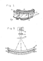
- Fig. 1 shows a perspective view of a holographic reflection visor 20 in accordance with the principles of the present invention.
- the visor 20 comprises a support structure 21 into which is disposed a holographic reflector 22.
- the visor 20 includes a face support 23 and a strap 24 for positioning the visor in proper position relative to the eyes of the user.
- Fig. 2 shows an expanded cross-sectional view of one embodiment of the holographic reflector 22 of the present invention.
- the reflector 22 is comprised of a first or top substrate 30, which may be comprised of glass or plastic, or the like.
- a first hologram 31 is disposed on the bottom surface of the first substrate 30.
- the first hologram may be comprised of a material such as dichromated gelatin, or the like.
- a second or bottom substrate 34 has a second hologram 33 disposed on the top surface thereof.
- the two holograms 31, 33 are disposed on their respective substrates 30, 34 so that they may be placed adjacent to each other.
- the two holograms 31, 33 with their respective substrates 30, 34 are bonded together by means of an adhesive 32, such as transparent epoxy, or the like.
- the two holograms 31, 33 and their respective substrates 30, 34 are generally conterminous as would be the case when supported in a visor, or the like.
- the holographic reflector 22 has a predetermined contour which is determined by the size of the particular visor or goggle arrangement into which the reflector 22 is placed.
- the holograms 31, 33 have fringes which are formed relative to the particular contour of the respective substrates 30, 34.
- the holographic fringes have a predetermined slant with respect to a normal to the particular substrate.
- the fringe slant is the angular orientation of the fringes in the hologram with respect to the normal to the surface of the substrate.
- the fringes are parallel to the surface of the substrates 30,34 of each hologram 31,33, and the fringe spacing of each hologram 31, 33 differs by a predetermined amount.
- the fringes are uniformly slanted with respect to the normal to the surface of the substrates 30, 34 but are oppositely aligned with respect to each other and to the normal.
- the fringe spacings of the two holograms 31, 33 are substantially identical in this embodiment.
- the fringe spacings and slant angles may be made different in order to achieve an asymmetric angular or wavelength - rejection characteristic.
- Fig. 2a shows a second construction of a holographic reflector 22a.
- This construction comprises a single substrate 30 onto which both holograms 31, 33 are disposed. Such a construction eliminates the need for a second substrate.
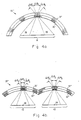
- Fig. 3a shows an illustration representative of a portion of a holographic visor employing a holographic reflector 22' in accordance with the present invention.
- Fig. 3a shows the angular protection provided by a slanted fringe device.
- each of the holograms 31 33' reflects laser radiation within a predetermined angular range.
- the first hologram 31' reflects within angular range ⁇ 1
- the second hologram 33' reflects within angular range ⁇ 2 .
- the fringe angle within each hologram 31', 33' remains the same overthe full surface thereof.
- angular coverage (shown as brackets 36, 37) provided by the reflector 22' completely protects the areas in which a viewer's eyes, represented by points 38, 39, may be positioned within a very largeangularsubtence of the visor.
- Fig. 3b illustrates a set of similar holographic reflectors 26' utilized in a goggle device.
- Fig. 4a shows a second embodiment of a holographic visor employing a holographic reflector 22' in accordance with the present invention.
- This embodiment employs holograms 31", 33" having fringes which are parallel to the substrate surface, but whose relative fringe spacing differs by a predetermined amount.
- each of the holograms 31", 33” protect a predetermined angular subtence which is shown as ⁇ 3 for the first hologram 31" and segments A04 and ⁇ 5 for the second hologram 33".
- the first and second holograms 31 ", 33” are designed so that each hologram reflects a different predetermined peak wavelength but the wavelength reflec-- tion bandwidths of both holograms 31', 33' overlap, although this is not an absolute requirement.
- This difference in peak reflection wavelength is accomplished by controlling the fringe spacing and slant angle of each hologram 31", 33".
- the two holograms 31 ", 33” protect the entire area of the eyes 38, 39, as shown by bracket 41.
- Fig. 4b illustrates a second embodiment of a goggle device employing a holographic reflector 26" which utilizes the parallel fringe holograms 31", 33" described with reference to Fig. 4a.
- Each hologram set protects one of the eyes 38, 39 as shown by brackets 42, 43.
- FIG. 5 illustrates a typical system which may be employed to manufacture the holograms utilized in the parallel fringe devices of the present invention.
- a laser light source 50 is utilized to provide a point source light image such as may be accomplished by use of a focusing lens 51 and a pinhole aperture 52.
- the light emitted through the aperture 52 is reflected from a front surface mirror 56.
- the light rays are transmitted through a substrate 53 which has a holographic recording material 54 disposed on one surface thereof.
- An index matching fluid 55 such as mineral oil, or the like, is disposed between the holographic material 54 and the mirror 56.
- the various elements (53-56) are disposed in a support housing 57. The light rays reflect from the mirror 56 back through the fluid 55, the holographic recording material 54 and substrate 53.
- the interference patterns caused by the counter-propagating light rays form a hologram in the recording material 54.
- the substrate 53 and the holographic material 54 are removed after the hologram has been recorded and subjected to further processing to finalize the peak wavelength at which the completed hologram reflects light.
- This processing is generally well-known in art and will not be described herein.
- the specific manufacturing methods which may be used to construct such holograms are described in numerous sources, including books entitled "Optical Holography” by Collier et al, Academic Press, 1971, and "Holographic Recording Materials” edited by H. M Smith, Springer Verlag, 1977.
- Figs. 6 and 7 show graphs of reflection efficiency versus angle of incidence for the parallel fringe hologram devices and slanted fringe hologram devices, respectively.
- the angular coverages of the various holograms 31', 33', 31 ", 33" shown in Figs. 6 and 7 correspond to the angular coverages shown in Figs. 3 and 4, respectively.
- the angular coverage provided by holograms 31', 33' are shown by graphs 31a, 33a in Fig. 7, while the angular coverage provided by holograms31 ",33” are shown in graphs 31b, 33b of Fig. 6.
- the horizontal arrows indicate the total angular coverages provided by the respective holographic reflectors.
- a holographic reflector may be designed utilizing either parallel or slanted fringes to provide a minimum of OD 3.0 protection from laser radiation at 0.53 ⁇ m.
- OD or optical density
- a power ratio of 1000 is OD 3.0.
- a visor with a radius of curvature of 11.4 cm (4.5 inches) may be placed at a distance of 8.9 cm (3.5 inches) from the eyes.
- the holographic reflector comprises two holograms, one with a peakwavelength at 0.535 pm covering incident angles from -20° to +20°, and the other at 0.55 pm covering incident angles from -29° to -19° and +19° to +29°.
- Each hologram should have a peak efficiency of about OD 4.5 in order to provide overall laser radiation rejection of OD 3.0.
- two holographic reflectors of the same design will be placed at a distance of 3.2 cm (1.25 inches) from the eyes to provide the same OD 3.0 rejection.
- a fringe slant angle of 10° allows a visor design with a visor-to-eye distance of approximately 7 cm (2.75 inches) for two holograms peaked at 0.535 pm.
- One hologram covers incident angles from -3° to +36° and the other covers angles from -36° to +3°.
- the holograms may be placed at a distance of 2.5 cm (1.0 inch) from the eyes.
- a parallel fringe device providing such protection at 1.06 pm comprises two holograms, one reflecting a peak wavelength at 1.07 pm and the other having a peak wavelength at 1.1 pm.
- a 10° slanted fringe device has two holograms peaked at 1.07 pm.
- the device may employ either parallel fringe or slanted fringe holograms which individually reflect laser radiation within predetermined angular limits.
- the devices provide excellent laser radiation rejection while allowing clear vision at visible wavelengths.
Landscapes
- Physics & Mathematics (AREA)
- Optics & Photonics (AREA)
- Health & Medical Sciences (AREA)
- Engineering & Computer Science (AREA)
- General Physics & Mathematics (AREA)
- Life Sciences & Earth Sciences (AREA)
- Heart & Thoracic Surgery (AREA)
- Vascular Medicine (AREA)
- Biomedical Technology (AREA)
- Animal Behavior & Ethology (AREA)
- General Health & Medical Sciences (AREA)
- Public Health (AREA)
- Veterinary Medicine (AREA)
- Ophthalmology & Optometry (AREA)
- Plasma & Fusion (AREA)
- Mechanical Engineering (AREA)
- Diffracting Gratings Or Hologram Optical Elements (AREA)
- Holo Graphy (AREA)
Abstract
Claims (3)
Applications Claiming Priority (2)
| Application Number | Priority Date | Filing Date | Title |
|---|---|---|---|
| US06/384,134 US4637678A (en) | 1982-06-01 | 1982-06-01 | Holographic laser protection device |
| US384134 | 1989-07-21 |
Publications (2)
| Publication Number | Publication Date |
|---|---|
| EP0110963A1 EP0110963A1 (fr) | 1984-06-20 |
| EP0110963B1 true EP0110963B1 (fr) | 1987-11-19 |
Family
ID=23516169
Family Applications (1)
| Application Number | Title | Priority Date | Filing Date |
|---|---|---|---|
| EP83902076A Expired EP0110963B1 (fr) | 1982-06-01 | 1983-05-26 | Dispositif de protection de laser holographique |
Country Status (6)
| Country | Link |
|---|---|
| US (1) | US4637678A (fr) |
| EP (1) | EP0110963B1 (fr) |
| DE (1) | DE3374606D1 (fr) |
| IL (1) | IL68803A (fr) |
| IT (1) | IT1172266B (fr) |
| WO (1) | WO1983004317A1 (fr) |
Families Citing this family (41)
| Publication number | Priority date | Publication date | Assignee | Title |
|---|---|---|---|---|
| US4802719A (en) * | 1983-08-22 | 1989-02-07 | Farrand Optical Co. | Infra-red laser shield |
| US4786125A (en) * | 1983-08-22 | 1988-11-22 | Farrand Optical Co. | Ocular protective apparatus |
| EP0194772A3 (fr) * | 1985-03-13 | 1987-09-30 | Gec Avionics Limited | Hologrammes |
| US4830441A (en) * | 1987-03-25 | 1989-05-16 | Kaiser Optical Systems | Holographic filter construction for protective eyewear |
| LU86927A1 (de) * | 1987-06-19 | 1988-07-14 | Europ Communities | Kontinuierlich variables laserstrahl-daempfungsglied |
| GB8805267D0 (en) * | 1988-03-04 | 1988-04-07 | Marconi Gec Ltd | Frequency selective optical filter elements |
| US5162927A (en) * | 1988-06-15 | 1992-11-10 | Hughes Aircraft Company | High efficiency holograms by multiple-layer holography |
| US5013107A (en) * | 1988-09-15 | 1991-05-07 | Biles Jonathan R | Polarization selective holographic optical element |
| US5179630A (en) * | 1988-10-06 | 1993-01-12 | Kaiser Optical Systems, Inc. | Laser protection window with tilted modulated index of refraction filter elements |
| US5082337A (en) * | 1988-12-16 | 1992-01-21 | Hughes Aircraft Company | Filter device employing a holographic element |
| US4978182A (en) * | 1989-10-23 | 1990-12-18 | Kaiser Optical Systems | Laser protection visor with ellipsoidal geometry |
| US5103323A (en) * | 1990-04-18 | 1992-04-07 | Holographic Optics, Inc. | Multi-layer holographic notch filter |
| US5198911A (en) * | 1990-12-27 | 1993-03-30 | American Optical Corporation | Holographic optical notch reflectors |
| US5691830A (en) * | 1991-10-11 | 1997-11-25 | International Business Machines Corporation | Holographic optical system including waveplate and aliasing suppression filter |
| FR2687484A1 (fr) * | 1992-02-18 | 1993-08-20 | Sextant Avionique | Filtre holographique de protection contre des rayonnements, notamment laser. |
| US5221977A (en) * | 1992-02-25 | 1993-06-22 | Grumman Aerospace Corporation | Laser radiation protection system |
| USD349596S (en) | 1992-04-24 | 1994-08-16 | Roberta Booth | Combined cap visor and hologram |
| DE69317743T2 (de) * | 1992-12-17 | 1998-10-29 | Ibm | Holographisches System und Verfahren |
| CA2114703A1 (fr) * | 1993-02-22 | 1994-08-23 | Kenneth M. Baker | Filtre a ondes lumineuses directif et projecteur holographique pour sa production |
| FR2723532B1 (fr) * | 1994-08-11 | 1998-08-14 | Intertechnique Sa | Equipement de protection de tete pour pilote d'aeronefs militaires et procede de personnalisation d'un tel equipement |
| WO1996026461A1 (fr) * | 1995-02-22 | 1996-08-29 | Polaroid Corporation | Article recouvrant l'oeil portant un hologramme par reflexion decoratif |
| FR2742884B1 (fr) * | 1995-12-21 | 1998-02-06 | Thomson Csf | Rejecteur spectral grand champ angulaire et procede de fabrication |
| US5831769A (en) * | 1996-07-26 | 1998-11-03 | Smith; David C. | Protecting eyes and instruments from laser radiation |
| RU2158019C2 (ru) * | 1998-04-21 | 2000-10-20 | Таср Лимитед | Линзы для голографических очков (варианты) |
| JP2000139998A (ja) * | 1998-11-16 | 2000-05-23 | Slt Japan:Kk | 医療用レーザ光の遮断用バイザー |
| US6378133B1 (en) | 1998-11-17 | 2002-04-30 | S.L.T. Japan Co., Ltd. | Visor for intercepting laser light for medical treatment |
| US6021520A (en) * | 1999-04-21 | 2000-02-08 | Wang-Lee; Min-Young | Eyeshield for a welder's mask |
| US6923537B2 (en) * | 2002-08-09 | 2005-08-02 | Gentex Corporation | Eyewear for ballistic and light protection |
| US6637877B1 (en) | 2002-08-09 | 2003-10-28 | Gentex Corporation | Eyewear for ballistic and light protection |
| US20070105254A1 (en) * | 2004-10-25 | 2007-05-10 | Research Investment Network, Inc. | Method for making a multi-layer diffractive optics memory |
| JP4811701B2 (ja) * | 2004-12-28 | 2011-11-09 | 山本光学株式会社 | 保護眼鏡用レンズ |
| JP2009020134A (ja) * | 2007-07-10 | 2009-01-29 | Sharp Corp | ホログラム素子、ホログラム素子作製装置、ホログラム素子作製方法、およびホログラム再生装置 |
| US8371705B2 (en) * | 2008-03-11 | 2013-02-12 | The United States Of America As Represented By The Secretary Of The Army | Mirrors and methods of making same |
| GB201117480D0 (en) * | 2011-10-10 | 2011-11-23 | Palikaras George | Filter |
| US9949517B2 (en) * | 2013-11-13 | 2018-04-24 | Encompass Group, Llc | Medical face shield |
| US20150128323A1 (en) * | 2013-11-13 | 2015-05-14 | Encampass Group, LLC | Medical face shield |
| GB201604995D0 (en) | 2016-03-24 | 2016-05-11 | Bae Systems Plc | Filter |
| GB201604994D0 (en) | 2016-03-24 | 2016-05-11 | Bae Systems Plc | Filter |
| EP3540480A1 (fr) * | 2018-03-16 | 2019-09-18 | BAE SYSTEMS plc | Filtre optique |
| EP3765874A1 (fr) * | 2018-03-16 | 2021-01-20 | BAE SYSTEMS plc | Filtre optique |
| US11927781B2 (en) | 2018-03-16 | 2024-03-12 | Bae Systems Plc | Optical device |
Citations (1)
| Publication number | Priority date | Publication date | Assignee | Title |
|---|---|---|---|---|
| EP0031278A1 (fr) * | 1979-12-19 | 1981-07-01 | ETAT-FRANCAIS représenté par le Délégué Général pour l' Armement | Filtre optique interférentiel de protection contre les radiations infrarouges et application |
Family Cites Families (6)
| Publication number | Priority date | Publication date | Assignee | Title |
|---|---|---|---|---|
| US3675990A (en) * | 1970-06-16 | 1972-07-11 | Bell Telephone Labor Inc | Reflective-type narrow band filter |
| US4245882A (en) * | 1977-11-04 | 1981-01-20 | Environmental Research Institute Of Michigan | Doubly modulated on-axis thick hologram optical element |
| DE3012550C2 (de) * | 1980-03-31 | 1982-10-28 | Transformatoren Union Ag, 7000 Stuttgart | Flüssigkeitsgekühlter Transformator für große Leistungen |
| DE3012500C2 (de) * | 1980-03-31 | 1982-11-18 | Erwin Sick Gmbh Optik-Elektronik, 7808 Waldkirch | Retroreflektor |
| US4359259A (en) * | 1980-04-29 | 1982-11-16 | The United States Of America As Represented By The Secretary Of The Air Force | Holographic multiplexer/demultiplexer |
| US4412719A (en) * | 1981-04-10 | 1983-11-01 | Environmental Research Institute Of Michigan | Method and article having predetermined net reflectance characteristics |
-
1982
- 1982-06-01 US US06/384,134 patent/US4637678A/en not_active Expired - Lifetime
-
1983
- 1983-05-26 EP EP83902076A patent/EP0110963B1/fr not_active Expired
- 1983-05-26 WO PCT/US1983/000842 patent/WO1983004317A1/fr not_active Ceased
- 1983-05-26 DE DE8383902076T patent/DE3374606D1/de not_active Expired
- 1983-05-27 IL IL68803A patent/IL68803A/xx not_active IP Right Cessation
- 1983-05-31 IT IT48400/83A patent/IT1172266B/it active
Patent Citations (1)
| Publication number | Priority date | Publication date | Assignee | Title |
|---|---|---|---|---|
| EP0031278A1 (fr) * | 1979-12-19 | 1981-07-01 | ETAT-FRANCAIS représenté par le Délégué Général pour l' Armement | Filtre optique interférentiel de protection contre les radiations infrarouges et application |
Also Published As
| Publication number | Publication date |
|---|---|
| IT1172266B (it) | 1987-06-18 |
| WO1983004317A1 (fr) | 1983-12-08 |
| DE3374606D1 (en) | 1987-12-23 |
| EP0110963A1 (fr) | 1984-06-20 |
| US4637678A (en) | 1987-01-20 |
| IT8348400A0 (it) | 1983-05-31 |
| IL68803A0 (en) | 1983-09-30 |
| IL68803A (en) | 1986-10-31 |
Similar Documents
| Publication | Publication Date | Title |
|---|---|---|
| EP0110963B1 (fr) | Dispositif de protection de laser holographique | |
| US4601533A (en) | Laser eye protection visor using multiple holograms | |
| US5539544A (en) | Holographic filter for protection from radiation, notably laser radiation | |
| US5103323A (en) | Multi-layer holographic notch filter | |
| US4830441A (en) | Holographic filter construction for protective eyewear | |
| US3792916A (en) | Anti-laser optical filter assembly | |
| EP0349884B1 (fr) | Ecran diffuseur/filtre à persiennes laminaire coloré à optique de diffraction d'ordre zéro supprimée | |
| US4978182A (en) | Laser protection visor with ellipsoidal geometry | |
| KR910000614B1 (ko) | 경사 굴절률 비구형 결합기 및 이를 사용하는 표시 시스템 | |
| US4848894A (en) | Contact lens with laser protection | |
| US5587847A (en) | Laser protection window using holographic optical element and channel plates | |
| US4802719A (en) | Infra-red laser shield | |
| US5071210A (en) | Sandwich reflection hologram | |
| EP0066496B1 (fr) | Procédé de réalisation d'un filtre optique à microvolets et utilisation pour un indicateur cathodique aéroporté | |
| US5005926A (en) | Ballistic protective laser shield | |
| US4879167A (en) | Real time holographic filter using nonlinear optical materials | |
| US4114978A (en) | Buried grating shared aperture device | |
| US5194989A (en) | Dielectric combiner including first and second dielectric materials having indices of refraction greater than 2.0 | |
| US5179630A (en) | Laser protection window with tilted modulated index of refraction filter elements | |
| EP0811859B1 (fr) | Réflecteur holographique et dispositif d'affichage à cristal liquide du type réflectif l'utilisant | |
| US4476161A (en) | Method of producing a buried long period grating | |
| EP0331469A2 (fr) | Filtres optiques sélectifs en fréquence | |
| CN106291916A (zh) | 光学斩波器、光调制系统及其进行光调制的方法 | |
| US11576456B2 (en) | Optical filter with stacked layers | |
| NO168612B (no) | Beskyttelsesanordning for holografilaser |
Legal Events
| Date | Code | Title | Description |
|---|---|---|---|
| PUAI | Public reference made under article 153(3) epc to a published international application that has entered the european phase |
Free format text: ORIGINAL CODE: 0009012 |
|
| 17P | Request for examination filed |
Effective date: 19840125 |
|
| AK | Designated contracting states |
Designated state(s): BE CH DE FR GB LI NL SE |
|
| RAP1 | Party data changed (applicant data changed or rights of an application transferred) |
Owner name: HUGHES AIRCRAFT COMPANY |
|
| GRAA | (expected) grant |
Free format text: ORIGINAL CODE: 0009210 |
|
| AK | Designated contracting states |
Kind code of ref document: B1 Designated state(s): BE CH DE FR GB LI NL SE |
|
| REF | Corresponds to: |
Ref document number: 3374606 Country of ref document: DE Date of ref document: 19871223 |
|
| ET | Fr: translation filed | ||
| PLBE | No opposition filed within time limit |
Free format text: ORIGINAL CODE: 0009261 |
|
| STAA | Information on the status of an ep patent application or granted ep patent |
Free format text: STATUS: NO OPPOSITION FILED WITHIN TIME LIMIT |
|
| 26N | No opposition filed | ||
| EAL | Se: european patent in force in sweden |
Ref document number: 83902076.5 |
|
| REG | Reference to a national code |
Ref country code: GB Ref legal event code: 732E |
|
| PGFP | Annual fee paid to national office [announced via postgrant information from national office to epo] |
Ref country code: SE Payment date: 20010504 Year of fee payment: 19 |
|
| PGFP | Annual fee paid to national office [announced via postgrant information from national office to epo] |
Ref country code: FR Payment date: 20010518 Year of fee payment: 19 |
|
| PGFP | Annual fee paid to national office [announced via postgrant information from national office to epo] |
Ref country code: DE Payment date: 20010522 Year of fee payment: 19 |
|
| PGFP | Annual fee paid to national office [announced via postgrant information from national office to epo] |
Ref country code: GB Payment date: 20010523 Year of fee payment: 19 |
|
| PGFP | Annual fee paid to national office [announced via postgrant information from national office to epo] |
Ref country code: CH Payment date: 20010529 Year of fee payment: 19 |
|
| PGFP | Annual fee paid to national office [announced via postgrant information from national office to epo] |
Ref country code: NL Payment date: 20010531 Year of fee payment: 19 |
|
| PGFP | Annual fee paid to national office [announced via postgrant information from national office to epo] |
Ref country code: BE Payment date: 20010717 Year of fee payment: 19 |
|
| REG | Reference to a national code |
Ref country code: GB Ref legal event code: IF02 |
|
| REG | Reference to a national code |
Ref country code: GB Ref legal event code: 732E |
|
| PG25 | Lapsed in a contracting state [announced via postgrant information from national office to epo] |
Ref country code: GB Free format text: LAPSE BECAUSE OF NON-PAYMENT OF DUE FEES Effective date: 20020526 |
|
| PG25 | Lapsed in a contracting state [announced via postgrant information from national office to epo] |
Ref country code: SE Free format text: LAPSE BECAUSE OF NON-PAYMENT OF DUE FEES Effective date: 20020527 |
|
| PG25 | Lapsed in a contracting state [announced via postgrant information from national office to epo] |
Ref country code: LI Free format text: LAPSE BECAUSE OF NON-PAYMENT OF DUE FEES Effective date: 20020531 Ref country code: CH Free format text: LAPSE BECAUSE OF NON-PAYMENT OF DUE FEES Effective date: 20020531 Ref country code: BE Free format text: LAPSE BECAUSE OF NON-PAYMENT OF DUE FEES Effective date: 20020531 |
|
| REG | Reference to a national code |
Ref country code: FR Ref legal event code: TP Ref country code: FR Ref legal event code: CD Ref country code: FR Ref legal event code: CA |
|
| PG25 | Lapsed in a contracting state [announced via postgrant information from national office to epo] |
Ref country code: NL Free format text: LAPSE BECAUSE OF NON-PAYMENT OF DUE FEES Effective date: 20021201 |
|
| PG25 | Lapsed in a contracting state [announced via postgrant information from national office to epo] |
Ref country code: DE Free format text: LAPSE BECAUSE OF NON-PAYMENT OF DUE FEES Effective date: 20021203 |
|
| EUG | Se: european patent has lapsed | ||
| GBPC | Gb: european patent ceased through non-payment of renewal fee |
Effective date: 20020526 |
|
| REG | Reference to a national code |
Ref country code: CH Ref legal event code: PL |
|
| PG25 | Lapsed in a contracting state [announced via postgrant information from national office to epo] |
Ref country code: FR Free format text: LAPSE BECAUSE OF NON-PAYMENT OF DUE FEES Effective date: 20030131 |
|
| NLV4 | Nl: lapsed or anulled due to non-payment of the annual fee |
Effective date: 20021201 |
|
| REG | Reference to a national code |
Ref country code: FR Ref legal event code: ST |