EP0111006B1 - Signalgenerator zum steuern eines optischen kopfes - Google Patents
Signalgenerator zum steuern eines optischen kopfes Download PDFInfo
- Publication number
- EP0111006B1 EP0111006B1 EP83901635A EP83901635A EP0111006B1 EP 0111006 B1 EP0111006 B1 EP 0111006B1 EP 83901635 A EP83901635 A EP 83901635A EP 83901635 A EP83901635 A EP 83901635A EP 0111006 B1 EP0111006 B1 EP 0111006B1
- Authority
- EP
- European Patent Office
- Prior art keywords
- photosensitive elements
- optical head
- recording medium
- sum
- control signal
- Prior art date
- Legal status (The legal status is an assumption and is not a legal conclusion. Google has not performed a legal analysis and makes no representation as to the accuracy of the status listed.)
- Expired
Links
Images


Classifications
-
- G—PHYSICS
- G11—INFORMATION STORAGE
- G11B—INFORMATION STORAGE BASED ON RELATIVE MOVEMENT BETWEEN RECORD CARRIER AND TRANSDUCER
- G11B7/00—Recording or reproducing by optical means, e.g. recording using a thermal beam of optical radiation by modifying optical properties or the physical structure, reproducing using an optical beam at lower power by sensing optical properties; Record carriers therefor
- G11B7/12—Heads, e.g. forming of the optical beam spot or modulation of the optical beam
- G11B7/13—Optical detectors therefor
-
- G—PHYSICS
- G11—INFORMATION STORAGE
- G11B—INFORMATION STORAGE BASED ON RELATIVE MOVEMENT BETWEEN RECORD CARRIER AND TRANSDUCER
- G11B7/00—Recording or reproducing by optical means, e.g. recording using a thermal beam of optical radiation by modifying optical properties or the physical structure, reproducing using an optical beam at lower power by sensing optical properties; Record carriers therefor
- G11B7/08—Disposition or mounting of heads or light sources relatively to record carriers
- G11B7/09—Disposition or mounting of heads or light sources relatively to record carriers with provision for moving the light beam or focus plane for the purpose of maintaining alignment of the light beam relative to the record carrier during transducing operation, e.g. to compensate for surface irregularities of the latter or for track following
- G11B7/0901—Disposition or mounting of heads or light sources relatively to record carriers with provision for moving the light beam or focus plane for the purpose of maintaining alignment of the light beam relative to the record carrier during transducing operation, e.g. to compensate for surface irregularities of the latter or for track following for track following only
- G11B7/0906—Differential phase difference systems
-
- G—PHYSICS
- G11—INFORMATION STORAGE
- G11B—INFORMATION STORAGE BASED ON RELATIVE MOVEMENT BETWEEN RECORD CARRIER AND TRANSDUCER
- G11B7/00—Recording or reproducing by optical means, e.g. recording using a thermal beam of optical radiation by modifying optical properties or the physical structure, reproducing using an optical beam at lower power by sensing optical properties; Record carriers therefor
- G11B7/08—Disposition or mounting of heads or light sources relatively to record carriers
- G11B7/09—Disposition or mounting of heads or light sources relatively to record carriers with provision for moving the light beam or focus plane for the purpose of maintaining alignment of the light beam relative to the record carrier during transducing operation, e.g. to compensate for surface irregularities of the latter or for track following
- G11B7/0943—Methods and circuits for performing mathematical operations on individual detector segment outputs
-
- G—PHYSICS
- G11—INFORMATION STORAGE
- G11B—INFORMATION STORAGE BASED ON RELATIVE MOVEMENT BETWEEN RECORD CARRIER AND TRANSDUCER
- G11B7/00—Recording or reproducing by optical means, e.g. recording using a thermal beam of optical radiation by modifying optical properties or the physical structure, reproducing using an optical beam at lower power by sensing optical properties; Record carriers therefor
- G11B7/08—Disposition or mounting of heads or light sources relatively to record carriers
- G11B7/09—Disposition or mounting of heads or light sources relatively to record carriers with provision for moving the light beam or focus plane for the purpose of maintaining alignment of the light beam relative to the record carrier during transducing operation, e.g. to compensate for surface irregularities of the latter or for track following
- G11B7/095—Disposition or mounting of heads or light sources relatively to record carriers with provision for moving the light beam or focus plane for the purpose of maintaining alignment of the light beam relative to the record carrier during transducing operation, e.g. to compensate for surface irregularities of the latter or for track following specially adapted for discs, e.g. for compensation of eccentricity or wobble
- G11B7/0956—Disposition or mounting of heads or light sources relatively to record carriers with provision for moving the light beam or focus plane for the purpose of maintaining alignment of the light beam relative to the record carrier during transducing operation, e.g. to compensate for surface irregularities of the latter or for track following specially adapted for discs, e.g. for compensation of eccentricity or wobble to compensate for tilt, skew, warp or inclination of the disc, i.e. maintain the optical axis at right angles to the disc
Definitions
- This invention relates to optical head control signal generators. Such generators are suitable for generating a tracking error signal to control an optical head employed in an optical information reproducing apparatus for optically reproducing with a beam of light, information recorded on a recording medium.
- a reproducing system for playing back a disc-shaped recording medium having information recording tracks in which information signals such as video signals and audio signals are recorded as a series of pits.
- the tracks on the recording medium are scanned by a beam of light such as a laser beam, and variations in the reflected light beam are detected to reproduce the recorded information signals.
- Such a system may, for example, be a video disc system or a digital audio disc system.
- a reproducing apparatus for such a system requires automatic control modes respectively for enabling the light beam to impinge on the tracks accurately at all times, and for focusing the light beam correctly on the tracks while scanning the tracks with the light beam.
- the automatic control modes for causing the light beam to impinge exactly on the tracks and for focusing the light beam correctly on the tracks are called tracking control and focusing control, respectively, and are indispensable in the optical information reproducing apparatus of the type described.
- control modes are normally achieved by causing the light beam to pass through an optical head onto the recording medium, receiving the light beam as modulated by the recording medium with the optical head, supplying the received light beam to a photosensitive element, generating control signals indicative of conditions in which the light beam reaches and is focused on the tracks based on a detected output from the photosensitive element, and driving optical means such as a lens or a mirror forming the optical head with the control signals for positional control.
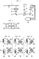
- Figure 1 of the accompanying drawings illustrates, by way of example, an optical arrangement for an optical head control signal generator for supplying control signals to such a control device for an optical head.
- a disc-shaped recording medium 1 carries information recording tracks composed of a series of pits.
- a laser beam emitted from a laser source 2 enters a polarizing prism 4 through a collimator lens 3.
- the laser beam directed to the left from the polarizing prism 4 reaches an objective lens 7 by way of a mirror 5 and a quarter-wave plate 6.
- the laser beam is then focused by the objective lens 7 onto the recording medium 1.
- the objective lens 7 is able to be driven for being positionally controlled, for example, in a direction traverse to the tracks and a direction towards or away from the recording medium 1.
- the laser beams falling on the recording medium 1 is modulated by the tracks, reflected back into the objective lens 7, and the travels via the quarter-wave plate 6, the mirror 5, the polarizing prism 4, and a prism 8 before reaching a photosensitive unit 9.
- the reflected light beam, or reading light beam, as modulated by the recording medium and supplied from the objective lens 7 forming an optical head is detected by photosensitive elements of the photosensitive unit 9. Variations in the detected light beam are sensed by the photosensitive unit 9, the output signal from which is supplied to a control signal generating circuit 10 which generates a control signal to drive, for example, the objective lens 7 for positional control such as tracking control or focusing control.
- the photosensitive unit 9 comprises four photosensitive elements D1, D2, D3 and D4, for example, as illustrated in Figure 2 of the accompanying drawings.
- the reading light beam as modulated by the recording medium 1 and guided by the objective lens 7 forms a spot on the photosensitive elements D1 to D4 as indicated by the dotted lines in Figure 2.
- the photosensitive elements D1 to D4 produce outputs dependent on beam spot portions respectively formed thereon, the outputs being available at respective output terminals d1 to d4.
- the information recording medium 1 comprise a series of pits having a depth which is one-quarter of the wavelength ⁇ of the incident laser beam.
- the laser beam irradiating the tracks is difracted and reflected by the pits.
- the reading light beam is modulated by the recording medium 1, reflected back through the objective lens 7, and reaches the photosensitive unit 9 to form the spot on the photosensitve elements D1 to D4.
- the reading light beam then produces a diffraction pattern corresponding to the positional relationship between one of the pits and the laser beam spot irradiating the pit.
- Figures 3A, 3B and 3C of the accompanying drawings illustrate the manner in which the foregoing process takes place.
- the reference letter a designates the positional relationship between a pit p and a laser beam spot I irradiating the pit p
- the reference letter b designates a diffraction pattern (hatched) formed on the exit pupil surface of the objective lens 7 by the reading light beam dependent on each of the above positional relationships.
- Four quarters D1', D2', D3' and D4' shown at b indicate portions in which the amounts of light are detected by the four photosensitive elements D1, D2, D3 and D4 respectively.
- the pit p moves from the position t1 to the position t2 with respect to the laser beam spot I.
- Figure 3A shows the condition in which the laster beam spot I is displaced to the right from the pit p.
- Figure 3B illustrates the condition in which the laser beam spot I is positioned centrally on the pit p, that is, the correct tracking condition.
- Figure 3C shows the condition in which the laser beam spot I is displaced to the left from the pit p.
- outputs from the photosenstive elements D1 to D4 may be supplied to and processed by a given control signal generator for producing a control signal, that is, a tracking control signal which varies dependent on the positional relationship of the laser beam spot I with respect to the pit p.
- the resulting tracking control signal is used to drive the objective lens 7 for positional control to maintain the correct condition shown in Figure 38.
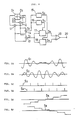
- FIG. 4 of the accompanying drawings shows one example of the control signal generating circuit (generator) 10 which produces a tracking control signal from the outputs of the photosensitive elements D1 to D4, and Figure 5 of the accompanying drawings shows corresponding waveforms.
- the control signal generator 10 the outputs from the photosensitive elements D1 to D4 are added by an adder 11, and the outputs from the photosensitive elements D2 and D3 are added by an adder 12.
- a subtractor 13 produces the difference between outputs from the adders 11 and 12, and an adder 14 adds the outputs from the adders 11 and 12.
- the substactor 13 When a laser beam spot moves, for example, from right to left across a track composed of a series of pits, the substactor 13 produces an output signal S1, as shown in Figure 5A, and the adder 14 produces an output signal S2 as shown in Figure 58.
- the signal S1 comprises a signal having a frequency band of the recorded information signal and varying each time the laser beam spot passes through a pit, the signal serving as a tracking error signal having positional information indicative of which position the laser beam spot is in with respect to the track.
- the signal S2 serves as a reproduced information signal.
- the output from the adder 14 is supplied to a pulse generator 15 which produces a pulse output signal S3 in response to rising edges of the signal S2 as shown in Figure 5C.
- the output from the adder 14 is also supplied to a pulse generator 16 which produces a pulse output signal S4 in response to falling edges of the signal S2 as shown in Figure SD.
- the subtractor 13 supplies the output to two sampling-hold circuits 17 and 18.
- the sampling-hold circuit 17 supplies an output signal S5, as shown in Figure 5E, which results from sampling and hold performed in response to the pulse signal S4.
- the output signals S5 and S6 from the sampling-hold circuits 17 and 18 have a polarity changing from negative to positive or vice versa when the laser beam spot is moved from right to left across a track, and have a level representative of the deviation of the laser beam spot from the centre of the track. Therefore, the output signals S5 and S6 can be employed as tracking control signals.
- the output signals S5 and S6 are supplied to a differential circuit 19 which produces the difference between the supplied signals, the difference serving as a more reliable tracking control signal supplied to an output terminal 20 which is then supplied for example to a driver circuit for driving the objective lens 7.
- the tracking control signal thus produced is affected by a tilt of the surface of the disc-shaped recording medium (hereinafter referred to as a "recording medium tilt") on which information recording tracks are formed, with respect to the plane lying perpendicular to the optical axis of the incident laser beam, and also by the positional relationship between pits forming one track and pits forming an adjacent track (hereinafter referred to as a "pit arrangement") in the direction along the information recording tracks.
- the tracking control signal is caused to vary dependent on the recording medium tilt and the pit arrangement.
- a disc-shaped recording medium has information recording tracks composed of rectangular pits p recorded at a constant recording signal wavelength T and each having a length of T/2, the pits p being spaced at an interval of T/2.
- the tracks are spaced at a track pitch g with the pit arrangement having a phase difference of r.
- FIGs 7A, 7B and 7C illustrate a tracking error signal S1 produced when the centre of the laser beam spot moves from the centre Q1 of one of the pits p forming one track to the centre Q2 of one of the pits p forming an adjacent track.
- the tracking error signal S1 is of a waveform as shown by a dot-and-dash line a.
- the tracking error signal S1 has a waveform as shown by a solid line P.
- the tracking error S1 has a waveform as shown by a broken line y.
- a recording medium tilt W is zero, and the phase difference r of the pit arrangement is zero.
- the recording medium tilt W is not zero but is ⁇ (for example, one degree), and the phase difference rofthe pit arrangement is zero.
- the recording medium tilt W is zero, and the phase difference r of the pit arrangement is T/2.
- the signal pattern a is zero with the signal patterns ⁇ and y are of equal amplitude and opposite phases.
- the signal pattern a is not zero, with the signal pattern ⁇ being of a smaller amplitude than when W and r are zero, and the signal pattern y being of a larger amplitude than when W and r are zero, resulting in an unbalanced condition.
- the phase difference r is T/2, the signal pattern a is zero and the signal patterns P and y are of equal amplitude and opposite phases, but are smaller in amplitude than when W and r are zero.
- the tracking error signal S1 is affected by the recording medium tilt W and the pit arrangement r, thereby to produce amplitude variations. Any tracking control signal generated on the basis of such a tracking error signal S1 contains an error and fails to perform correct tracking control.
- the diffraction patterns (enclosed in circles) shown in Figures 8A to 8D have hatched peak portions with surrounding lines serving as diagrams indicating equal levels.
- Four quarters D1'to D4' indicated by the two-dot-and-dash lines in Figures 8A to 8D correspond respectively to four photosensitive elements forming a photosensitive unit, for example, portions in which amounts of incident light are detected by the photosensitive elements D1 to D4.
- Figure 8A shows a diffraction pattern produced when the recording medium tilt W is zero and the phase difference r of the pit arrangement is also zero.
- the diffraction pattern of Figure 8B is produced when W is 6 (for example, one degree) and r is zero.
- Figure 8C illustrates a diffraction pattern produced when W is zero and r is T/2.
- Figure 8D shows a diffraction pattern produced when W is 8 (for example, one degree) and r is T/2.
- the difference between the amounts of light on the diagonal portions D1' and D4' is equal to the difference between the amounts of light on the diagonal portions D2' and D3', and a light distribution component which is symmetrical with respect to the line X-X orthe line Y-Y is small. Therefore, light distribution components which vary the amplitude of the tracking error signal S1 therebetween are small in the respective diffraction patterns of Figures 8A to 8D.
- any influence due to a recording medium tilt and a pit arrangement can be reduced by detecting the amount of light only in the outer peripheral portion of the diffraction pattern on the exit pupil surface of the objective lens 7 as shown in Figures 8A to 8D, thereby to generate a tracking error signal.
- an optical head control signal generator comprising:
- an embodiment of optical head control signal generator has an oppical arrangement similar to that shown in Figure 1 with the photosensitive unit arranged for detecting the amount of light only in the outer peripheral portion of a diffraction pattern formed on the exit pupil surface of the objective lens by a reading light beam.
- a tracking error signal is generated in response to an output signal from the photosensitive unit based on the detected quantity of light only in the outer peripheral portion of the diffraction pattern, and an optical head control signal is produced from the tracking error thus generated.
- an accurate tracking control signal can be produced on the basis of a tracking error signal which is subjected to greatly reduced adverse influences to recording medium tilt and the bit arrangement.
- An embodiment of optical head control signal generator according to the present invention has an optical arrangement as illustrated in Figure 1, except for the photosensitive unit.
- a photosensitive unit 9' has four phot- sensitive elements D1a, D2a, D3a and D4a for detecting amounts of light in the outer circumferential peripheral portion of a diffraction pattern on the exit pupil surface of the objective lens 7, and four photosensitive elements D1b, D2b, D3b, and D4b for detecting amounts of light in a central portion of the diffraction pattern on the exit pupil surface of the objective lens 7.
- the photosensitive elements D1a and D1b, D2a and D2b, D3a and D3b, and D4a and D4b correspond respectively to the photosensitive elements D1, D2, D3 and D4 shown in Figure 2.
- Output terminals dl a, d2a, d3a and d4a are connected to the photosensitive elements D1a, D2a, D3a and D4a, respectively, and output terminals d1b, d2b, d3b and d4b are connected to the photosensitive elements D1b, D2b, D3b, and D4b, respectively.
- Figure 10 shows a control signal generating circuit including the photosensitive unit 9' composed of the eight photosensitive elements D1 a to D4a and D1 b to D4b. Outputs from the photosensitive elements D1 and D4a are added by an adder 21, and outputs from the photosensitive elements D2a and D3a are added by the adder 22. A subtractor 23 produces the difference between outputs from the adders 21 and 22. Outputs from the photosensitive elements D1b, D2b, D3b and D4b are added by adders 24, 25 and 26, and outputs from the adders 21, 22 and 26 are added by an adder 27.
- the subtractor 23 produces a tracking error signal S1' indicative of the difference betweeen the sum of the outputs from the photosensitive elements 01 a and D4a and the sum of the outputs from the photosensitive elements D2a and D3a.
- the adder 27 produces the total sum of the outputs from the eight photosensitive elements D1 a to D4a and D1 b to D4b.
- An output from the subtractor 23 is supplied to sampling-hold circuits 17 and 18 identical to those shown in Figure 1.
- An output from the adder 27 is supplied to pulse generators 15 and 16 identical to those shown in Figure 1.
- Outputs from the sampling-hold circuits 17 and 18 are supplied to a differential circuit 19 identical to that shown in Figure 1.
- a tracking control signal is then produced by the same operation as that of the circuit of Figure 1, and is supplied to an output terminal 20. Therefore, the pulse generator 15, the pulse generator 16, the sampling-hold circuits 17 and 18, and the differential circuit 19 form a synthesizing circuit 28 for generating a tracking control signal based on the output from the subtractor 23 and the output from the adder 27.
- the tracking error signal S1' from the subtractor 23 is produced on the basis of the outputs from the photosensitive elements D1a, D2a, D3a and D4a, that is, outputs indicative of the amounts of light only in the outer circumferential peripheral portion of the diffraction pattern formed on the exit pupil surface of the objective lens 7 by the reading light beam.
- the tracking error signal S1 suffers from no amplitude variation.
- all outputs from the eight photosensitive elements D1 a to D4a and D1 b to D4b are added to produce a reproduced information signal.
- the reading light beam can be utilized highly effectively for generating a reproduced information signal efficiently.
- the detection of the quantities of light only in the outer circumferential peripheral portion of a diffraction pattern produced on the exit pupil surface of the objective lens by the reading light beam in the optical head control signal generator may be effected by other means than the foregoing arrangement in which the photosensitive unit is divided into a photosensitive element area for detecting the amounts of light in the outer circumferential portion of the diffraction pattern and a photosensitive element area for detecting the quantities of light in the central portion of the diffraction pattern.
- Embodiments of optical head control signal generator according to the present invention are capable of generating a highly stable and accurate tracking control signal, and are therefore suitable for use, for example, in optical digital audio disc players (compact disc players), video disc players and optical disc memory players.
Landscapes
- Physics & Mathematics (AREA)
- Optics & Photonics (AREA)
- Mathematical Physics (AREA)
- Optical Recording Or Reproduction (AREA)
- Automatic Focus Adjustment (AREA)
- Optical Head (AREA)
Claims (3)
Priority Applications (1)
| Application Number | Priority Date | Filing Date | Title |
|---|---|---|---|
| AT83901635T ATE34242T1 (de) | 1982-05-31 | 1983-05-31 | Signalgenerator zum steuern eines optischen kopfes. |
Applications Claiming Priority (2)
| Application Number | Priority Date | Filing Date | Title |
|---|---|---|---|
| JP92383/82 | 1982-05-31 | ||
| JP57092383A JPS58208944A (ja) | 1982-05-31 | 1982-05-31 | 光学ヘツド制御信号発生装置 |
Publications (3)
| Publication Number | Publication Date |
|---|---|
| EP0111006A1 EP0111006A1 (de) | 1984-06-20 |
| EP0111006A4 EP0111006A4 (de) | 1985-02-18 |
| EP0111006B1 true EP0111006B1 (de) | 1988-05-11 |
Family
ID=14052898
Family Applications (1)
| Application Number | Title | Priority Date | Filing Date |
|---|---|---|---|
| EP83901635A Expired EP0111006B1 (de) | 1982-05-31 | 1983-05-31 | Signalgenerator zum steuern eines optischen kopfes |
Country Status (5)
| Country | Link |
|---|---|
| US (1) | US4654838A (de) |
| EP (1) | EP0111006B1 (de) |
| JP (1) | JPS58208944A (de) |
| DE (1) | DE3376595D1 (de) |
| WO (1) | WO1983004331A1 (de) |
Families Citing this family (18)
| Publication number | Priority date | Publication date | Assignee | Title |
|---|---|---|---|---|
| JPH0731819B2 (ja) * | 1985-03-22 | 1995-04-10 | 株式会社日立製作所 | 光デイスク装置 |
| JPH0640392B2 (ja) * | 1986-08-29 | 1994-05-25 | 三菱電機株式会社 | 光学式情報記録再生装置の集光スポツト位置検出装置 |
| JP2887273B2 (ja) * | 1987-05-22 | 1999-04-26 | パイオニア株式会社 | 光学式ピックアップ装置 |
| US4816665A (en) * | 1987-08-06 | 1989-03-28 | Maxtor Corporation | Sensor array for focus detection |
| US4958245A (en) * | 1988-04-07 | 1990-09-18 | Insite Peripherals, Inc. | Apparatus and method for optical servo control with media having information storage and servo control regions of different reflectivities |
| JP2701324B2 (ja) * | 1988-06-16 | 1998-01-21 | ソニー株式会社 | 光学ヘッド装置 |
| US5017768A (en) * | 1988-09-14 | 1991-05-21 | Copal Company Limited | Optical focusing control apparatus |
| JP2701392B2 (ja) * | 1988-12-14 | 1998-01-21 | ソニー株式会社 | フオーカスエラー検出回路 |
| KR940001999B1 (ko) * | 1989-06-06 | 1994-03-12 | 샤프 가부시끼가이샤 | 광 픽업장치 |
| JPH04205728A (ja) * | 1990-11-29 | 1992-07-27 | Pioneer Electron Corp | トラッキング誤差検出装置 |
| NL9100408A (nl) * | 1991-03-07 | 1992-10-01 | Philips Nv | Informatie-uitleesstelsel, alsmede een registratiedrager en uitleesinrichting voor toepassing in een dergelijk stelsel. |
| JP3166322B2 (ja) * | 1992-06-15 | 2001-05-14 | ソニー株式会社 | 再生方法、再生装置 |
| JPH0917029A (ja) | 1995-06-26 | 1997-01-17 | Pioneer Electron Corp | 光ディスクとその読取装置および光ディスク製造方法 |
| KR100200857B1 (ko) * | 1995-10-04 | 1999-06-15 | 윤종용 | 광픽업장치 |
| JP3529937B2 (ja) * | 1996-04-08 | 2004-05-24 | ローム株式会社 | 光ピックアップ装置 |
| JP2000339727A (ja) * | 1999-05-18 | 2000-12-08 | Lg Electronics Inc | 光記録媒体の記録再生方法 |
| DE19924733A1 (de) * | 1999-05-31 | 2000-12-07 | Thomson Brandt Gmbh | Gerät zum Lesen oder Beschreiben optischer Aufzeichnungsträger |
| JP2007509456A (ja) * | 2003-10-20 | 2007-04-12 | コーニンクレッカ フィリップス エレクトロニクス エヌ ヴィ | 光データ上に光学的に読出し可能なデータを書込みする方法及び機器 |
Citations (1)
| Publication number | Priority date | Publication date | Assignee | Title |
|---|---|---|---|---|
| EP0068904A1 (de) * | 1981-06-30 | 1983-01-05 | Storage Technology Corporation | Vorrichtung zum Auslesen von Informationen, welche in eine Spur eines lichtreflektierenden Tragers gespeichert sind |
Family Cites Families (9)
| Publication number | Priority date | Publication date | Assignee | Title |
|---|---|---|---|---|
| FR2266932B1 (de) * | 1973-03-02 | 1977-09-02 | Thomson Brandt | |
| NL182258C (nl) * | 1976-01-28 | 1988-02-01 | Philips Nv | Inrichting voor het uitlezen van een vlakke registratiedrager met een optisch uitleesbare informatiestructuur. |
| US4057833A (en) * | 1974-10-03 | 1977-11-08 | U.S. Philips Corporation | Centering detection system for an apparatus for playing optically readable record carriers |
| JPS5821334B2 (ja) * | 1978-12-25 | 1983-04-28 | 株式会社東芝 | 自動焦点調節装置 |
| JPS5647931A (en) * | 1979-09-21 | 1981-04-30 | Matsushita Electric Ind Co Ltd | Optical recording and reproducing device |
| JPS5774837A (en) * | 1980-10-25 | 1982-05-11 | Olympus Optical Co Ltd | Signal detection system of optical information reproducing device |
| JPS57111837A (en) * | 1980-12-27 | 1982-07-12 | Olympus Optical Co Ltd | Signal detecting system of optical information reader |
| JPS5814332A (ja) * | 1981-07-16 | 1983-01-27 | Mitsubishi Electric Corp | 光学式情報再生装置 |
| JPS5911543A (ja) * | 1982-07-10 | 1984-01-21 | Sony Corp | 光学式デイスク再生装置 |
-
1982
- 1982-05-31 JP JP57092383A patent/JPS58208944A/ja active Pending
-
1983
- 1983-05-31 EP EP83901635A patent/EP0111006B1/de not_active Expired
- 1983-05-31 US US06/576,391 patent/US4654838A/en not_active Expired - Fee Related
- 1983-05-31 WO PCT/JP1983/000172 patent/WO1983004331A1/ja not_active Ceased
- 1983-05-31 DE DE8383901635T patent/DE3376595D1/de not_active Expired
Patent Citations (1)
| Publication number | Priority date | Publication date | Assignee | Title |
|---|---|---|---|---|
| EP0068904A1 (de) * | 1981-06-30 | 1983-01-05 | Storage Technology Corporation | Vorrichtung zum Auslesen von Informationen, welche in eine Spur eines lichtreflektierenden Tragers gespeichert sind |
Also Published As
| Publication number | Publication date |
|---|---|
| DE3376595D1 (en) | 1988-06-16 |
| EP0111006A1 (de) | 1984-06-20 |
| US4654838A (en) | 1987-03-31 |
| JPS58208944A (ja) | 1983-12-05 |
| WO1983004331A1 (fr) | 1983-12-08 |
| EP0111006A4 (de) | 1985-02-18 |
Similar Documents
| Publication | Publication Date | Title |
|---|---|---|
| EP0111006B1 (de) | Signalgenerator zum steuern eines optischen kopfes | |
| EP0050967B1 (de) | Signalerkennungssystem für ein optisches Wiedergabegerät | |
| US4507763A (en) | Optical information recording and/or reproducing apparatus and optical record medium for use in such apparatus | |
| US4293944A (en) | Information play-back apparatus with astigmatic auto-focusing | |
| US4445209A (en) | Dithered focusing systems | |
| CA1057397A (en) | Synchronous detection tracking | |
| JP2725632B2 (ja) | 光ヘッド装置 | |
| EP0162702B1 (de) | Spursteueranordnung zur Verwendung bei optischen Plattengeräten | |
| US4816665A (en) | Sensor array for focus detection | |
| KR880002326B1 (ko) | 디스크 재생장치 | |
| US5210730A (en) | Tracking error detecting apparatus for use in multibeam optical disk device | |
| EP0116467B1 (de) | Optische Plattenspieler | |
| GB1572544A (en) | Apparatus for optically detecting information recorded on a carrier | |
| US5042019A (en) | Method of and apparatus for seeking a desired track by counting track crossing signals which are detected within a predetermined time interval | |
| EP0536718A2 (de) | Optisches Wiedergabegerät | |
| US4525825A (en) | Method and apparatus for detecting focussing and tracking error signals | |
| US5373437A (en) | Device for and method of reducing cross talk in optical disk device | |
| CA1129093A (en) | Optical head | |
| JP3186221B2 (ja) | 光学式記録情報再生装置 | |
| US5293366A (en) | Information recording and reproducing apparatus provided with means for adding to a tracking signal offset corresponding to the positional deviation of a recording spot and a reproducing spot | |
| US5260930A (en) | Optical information recording medium and reproducing apparatus for reproducing information from the medium | |
| US5060217A (en) | Optical head devices for use in recording and/or reproduction of information | |
| JP3136372B2 (ja) | マルチビーム装置 | |
| JP2760408B2 (ja) | 光学的情報記録再生装置 | |
| JPH0656661B2 (ja) | スポツト位置合わせ方法および光ディスク装置 |
Legal Events
| Date | Code | Title | Description |
|---|---|---|---|
| PUAI | Public reference made under article 153(3) epc to a published international application that has entered the european phase |
Free format text: ORIGINAL CODE: 0009012 |
|
| 17P | Request for examination filed |
Effective date: 19840218 |
|
| AK | Designated contracting states |
Designated state(s): AT DE FR GB SE |
|
| 17Q | First examination report despatched |
Effective date: 19860515 |
|
| GRAA | (expected) grant |
Free format text: ORIGINAL CODE: 0009210 |
|
| AK | Designated contracting states |
Kind code of ref document: B1 Designated state(s): AT DE FR GB SE |
|
| REF | Corresponds to: |
Ref document number: 34242 Country of ref document: AT Date of ref document: 19880515 Kind code of ref document: T |
|
| REF | Corresponds to: |
Ref document number: 3376595 Country of ref document: DE Date of ref document: 19880616 |
|
| ET | Fr: translation filed | ||
| PLBE | No opposition filed within time limit |
Free format text: ORIGINAL CODE: 0009261 |
|
| STAA | Information on the status of an ep patent application or granted ep patent |
Free format text: STATUS: NO OPPOSITION FILED WITHIN TIME LIMIT |
|
| 26N | No opposition filed | ||
| PGFP | Annual fee paid to national office [announced via postgrant information from national office to epo] |
Ref country code: SE Payment date: 19930518 Year of fee payment: 11 |
|
| PGFP | Annual fee paid to national office [announced via postgrant information from national office to epo] |
Ref country code: AT Payment date: 19930526 Year of fee payment: 11 Ref country code: FR Payment date: 19930526 Year of fee payment: 11 |
|
| PGFP | Annual fee paid to national office [announced via postgrant information from national office to epo] |
Ref country code: GB Payment date: 19930528 Year of fee payment: 11 |
|
| PGFP | Annual fee paid to national office [announced via postgrant information from national office to epo] |
Ref country code: DE Payment date: 19930729 Year of fee payment: 11 |
|
| PG25 | Lapsed in a contracting state [announced via postgrant information from national office to epo] |
Ref country code: AT Effective date: 19940531 Ref country code: GB Effective date: 19940531 |
|
| PG25 | Lapsed in a contracting state [announced via postgrant information from national office to epo] |
Ref country code: SE Effective date: 19940601 |
|
| GBPC | Gb: european patent ceased through non-payment of renewal fee |
Effective date: 19940531 |
|
| EUG | Se: european patent has lapsed |
Ref document number: 83901635.9 Effective date: 19950110 |
|
| PG25 | Lapsed in a contracting state [announced via postgrant information from national office to epo] |
Ref country code: FR Effective date: 19950131 |
|
| PG25 | Lapsed in a contracting state [announced via postgrant information from national office to epo] |
Ref country code: DE Effective date: 19950201 |
|
| EUG | Se: european patent has lapsed |
Ref document number: 83901635.9 |
|
| REG | Reference to a national code |
Ref country code: FR Ref legal event code: ST |