EP0111045A2 - Laseranordnung - Google Patents
Laseranordnung Download PDFInfo
- Publication number
- EP0111045A2 EP0111045A2 EP83105118A EP83105118A EP0111045A2 EP 0111045 A2 EP0111045 A2 EP 0111045A2 EP 83105118 A EP83105118 A EP 83105118A EP 83105118 A EP83105118 A EP 83105118A EP 0111045 A2 EP0111045 A2 EP 0111045A2
- Authority
- EP
- European Patent Office
- Prior art keywords
- laser
- gas
- tubes
- arrangement according
- radial compressor
- Prior art date
- Legal status (The legal status is an assumption and is not a legal conclusion. Google has not performed a legal analysis and makes no representation as to the accuracy of the status listed.)
- Granted
Links
Images

Classifications
-
- H—ELECTRICITY
- H01—ELECTRIC ELEMENTS
- H01S—DEVICES USING THE PROCESS OF LIGHT AMPLIFICATION BY STIMULATED EMISSION OF RADIATION [LASER] TO AMPLIFY OR GENERATE LIGHT; DEVICES USING STIMULATED EMISSION OF ELECTROMAGNETIC RADIATION IN WAVE RANGES OTHER THAN OPTICAL
- H01S3/00—Lasers, i.e. devices using stimulated emission of electromagnetic radiation in the infrared, visible or ultraviolet wave range
- H01S3/02—Constructional details
- H01S3/03—Constructional details of gas laser discharge tubes
- H01S3/036—Means for obtaining or maintaining the desired gas pressure within the tube, e.g. by gettering, replenishing; Means for circulating the gas, e.g. for equalising the pressure within the tube
-
- H—ELECTRICITY
- H01—ELECTRIC ELEMENTS
- H01S—DEVICES USING THE PROCESS OF LIGHT AMPLIFICATION BY STIMULATED EMISSION OF RADIATION [LASER] TO AMPLIFY OR GENERATE LIGHT; DEVICES USING STIMULATED EMISSION OF ELECTROMAGNETIC RADIATION IN WAVE RANGES OTHER THAN OPTICAL
- H01S3/00—Lasers, i.e. devices using stimulated emission of electromagnetic radiation in the infrared, visible or ultraviolet wave range
- H01S3/05—Construction or shape of optical resonators; Accommodation of active medium therein; Shape of active medium
- H01S3/06—Construction or shape of active medium
- H01S3/07—Construction or shape of active medium consisting of a plurality of parts, e.g. segments
- H01S3/073—Gas lasers comprising separate discharge sections in one cavity, e.g. hybrid lasers
Definitions
- the invention relates to a laser arrangement based on the gas transport principle with gas circulation, cooling and excitation system and rapid longitudinal gas flow.
- the decrease in performance is due to the fact that the line width increases with increasing temperature, the excitation energy is distributed over an increasing number of rotation lines, the number of deactivating bumps increases and the occupation of the laser end level by thermal excitation increases and thus the inversion decreases (K. Gürs, "Laser 75 Opto-Electronics", Conference proceedings, pp. 30 - 37).
- Suitable lasers consist of an active area in which the gas is excited, with an adjacent or integrated optical resonator, the gas routing system with a built-in cooler and a pump. Since large amounts of heat have to be dissipated, large amounts of gas have to be pumped around. The corresponding known lasers are large and complex, their use is limited because of their unwieldiness.
- the interaction path of the excited active molecules in the laser resonator is relatively small. Since the power density of the lasers is not far above the saturation power, excitation energy is lost in this way, and the lasers have a comparatively low efficiency of e.g. less than approx. 10%. In addition, the transverse excitation is relatively inhomogeneous, which results in unfavorable beam properties.
- pumps and blowers of various types are used in the known gas transport lasers, for example rotary vane pumps, roots blowers (K. Gürs, "Laser 75, Opto-Electronics", Conference Proceedings, pp. 30-37 or H. Herbrich and B. Dellith, DE-OS 29 25 829), cross-flow fan (JD Foster, US Pat. No. 4,099,143) or radial fan (HJ Seguin and G. Sedgwick, Appl. Optics 11, 1972, 745-748 or K. Sasaki et al., European patent application 80 100 870.7, publication no. 0 015 003).
- the various components must be identified separately as subsystems with a defined function.
- the present invention is therefore based on the object of developing a particularly compact and powerful laser arrangement in which all functions are fully integrated, so that very short distances can be realized in combination with a new gas guide without intermediate pipelines.
- At least one radial compressor with diffuser and gas deflecting elements or sheets is provided for gas circulation and at least two longitudinal tubes, which together form the laser resonator, on the one hand open directly into the inlet of the radial compressor or lead away from the diffuser and that the longitudinal tubes on the other hand, are connected to at least one flow channel leading directly from the diffuser or opening into the inlet of the radial compressor and designed as a cooling section via shaped gas deflection parts, so that at least one integrated circuit section for the laser gas is created.
- the invention not only eliminates the disadvantages of the known gas transport lasers already mentioned.
- a gas transport laser is provided as a particularly compact and powerful system with technically simple means.
- the laser is small, has a high output, high efficiency and is inexpensive to manufacture.
- the various functions are fully integrated in the arrangement according to the invention. Otherwise, the arrangement can be carried out in two different ways, depending on whether the cooler is accommodated on the pressure side and the laser tubes on the suction side of the radial compressor, or vice versa.
- the laser gas is drawn off in the middle of the longitudinal tube 1 at high speed and flows directly into the aerodynamically shaped inlet 2 of a radial compressor 3 without an intermediate pipeline.
- the axis of the radial compressor 3 becomes perpendicular to the axis of the arranged from the two longitudinal tubes 1 formed laser resonator.
- the gas comes through the diffuser 4 and the two spiral gas deflecting elements 5 without piping directly into the wide flow channel 6, which preferably includes the heat exchanger 7, and is redirected or returned to the laser tube 1 on both sides.
- the actual laser tube is made in a known manner from an insulating material 8 such as glass, ceramic or plastic and embedded in the longitudinal tube 1.
- the laser tube widens at the location of the ring-shaped electrode 9.
- the ring electrode 9 preferably does not lie against the wall, but part of the laser gas can flow outside the ring into the remaining section of the laser tube 1.
- a corresponding distance between the electrodes 9 and the end plate 10 of the laser ensures that the gas discharge does not penetrate against the direction of flow towards the end plates 10 of the laser system.
- the two end parts of the entire laser system between a plane that passes approximately perpendicularly through the electrodes 9 and the end plates 10 are made of insulating material.
- the end plates are insulated and no gas discharge can form between the electrodes 9 and the end plates 10. If the cooler 7 is shortened accordingly, the distance between the electrode 9 and the end plates 10 can be made smaller in this case and the laser tube 1 can be used even better.
- the cooler 7 not only is the cooler 7 flowed through by water, but also the other parts heated by the laser gas are cooled with water or another coolant.
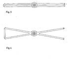
- the system can easily be brought to much higher performances. With a larger compressor and a larger pipe diameter, outputs of over 3 kW can be achieved. In terms of good beam quality, however, it is more favorable to use two thinner laser tubes in a parallel or crossed arrangement, as shown in FIGS. 3 and 4, instead of a tube with a correspondingly larger diameter. In both cases, the two tubes are optically connected by two (not shown) deflecting mirrors.
- the invention can also be implemented in such a way that the cooler is arranged on the suction side and the laser tubes on the pressure side.
- the laser gas flows through the cooler without passing through an intermediate pipe directly into the aerodynamically shaped inlet of the centrifugal compressor, and after exiting the compressor and flowing through the spiral (guide plates), it arrives directly in a laser tube or parallel arrangement flow channel formed by laser tubes is deflected at the ends of this flow channel and flows back into the cooler.
- a rotationally symmetrical arrangement in which the axis of rotation of the impeller and the axes of the laser tubes run parallel to one another is particularly favorable and is suitable for generating high laser powers.
- the laser gas is withdrawn through the cooler 7 arranged along the axis of the system, passes through a diffuser 4 and optionally a spiral in the form of gas baffles into an annular channel 11, which is in laser tubes 1 is divided.
- the laser tubes 1 do not have to fill the entire cross section of the annular region. Rather, the gas can be replaced by a limited number of e.g. six symmetrically arranged laser tubes 1 are passed through.
- the gas is returned to the cooler 7 in a molded part 12.
- the laser power is deflected from one tube into the next by means of suitably inclined mirrors 13, so that a laser oscillation can build up between the end mirrors 14 in this way.
- An end mirror is designed in a known manner as a partially transparent mirror; the laser emission can escape through it.
- a further doubling of the output can be achieved if two such systems with the same axis but in a mirror-image arrangement are put together on the side of the deflection molding or on the side of the impeller. Contamination of the mirrors is avoided if the flow direction is selected such that the gas movement, as shown in FIG. 6, leads away from the mirrors on both sides.
- the entire system can also be designed in a modular design in this case.
- the intermediate part of insulating material By building the intermediate part of insulating material, partial insulation of the deflecting part and additional use of a high-voltage electrode in the middle of the system, it is also possible to place the electrodes 9 at ground potential and to arrange them at the beginning of the laser tubes so that the laser tubes are of full length can be used as active areas.
- Intermediate electrodes can also be provided to improve the gas discharge (ignition and homogeneity).
Landscapes
- Physics & Mathematics (AREA)
- Electromagnetism (AREA)
- Engineering & Computer Science (AREA)
- Plasma & Fusion (AREA)
- Optics & Photonics (AREA)
- Lasers (AREA)
- Laser Surgery Devices (AREA)
- Semiconductor Lasers (AREA)
- Glass Compositions (AREA)
Abstract
Description
- Die Erfindung betrifft eine Laseranordnung nach dem Gastransport-Prinzip mit Gasumwälz-, Kühl- und Anregungssystem und schneller longitudinaler Gasströmung.
- Leistung, Verstärkung und Wirkungsgrad der Moleküllaser, insbesondere der C02-Laser, nehmen mit steigender Temperatur im Lasergas ab. Die Abnahme der Leistungsfähigkeit beruht darauf, daß mit zunehmender Temperatur die Linienbreite größer wird, die Anregungsenergie sich auf eine zunehmende Zahl von Rotationslinien verteilt, die Zahl der desaktivierenden Stöße zunimmt und die Besetzung des Laserendniveaus durch thermische Anregung zunimmt und damit die Inversion abnimmt (K. Gürs, "Laser 75 Opto-Electronics", Conference proceedings, S. 30 - 37).
- Aus diesem Grund wurden bereits Methoden entwickelt, die Wärme mit dem Lasergas durch Umwälzen und Kühlen des Gases abführen. Geeignete Laser bestehen aus einem aktiven Bereich, in dem das Gas angeregt wird, mit angrenzendem oder integriertem optischen Resonator, aus dem Gasführungssystem mit eingebautem Kühler und einer Pumpe. Da große Wärmemengen abzuführen sind, müssen große Gasmengen umgepumpt werden. Die entsprechenden bekannten Laser sind groß und aufwendig, ihre Einsatzmöglichkeit ist wegen ihrer Unhandlichkeit begrenzt.
- Dieser Nachteil tritt bei den longitudinal durchströmten Lasern besonders in Erscheinung, bei denen in den bekannten Anordnungen lange Gasleitungen erforderlich sind. Außerdem verursachen diese Leitungen einen entsprechend hohen Strömungswiderstand. Dadurch sinkt die Leistungsfähigkeit des Systems, oder man benötigt besonders große Pumpen.
- Bei den transversal durchströmten Systemen ist der Wechselwirkungsweg der angeregten aktiven Moleküle im Laserresonator relativ klein. Da die Leistungsdichte der Laser nicht weit über der Sättigungsleistung liegt, geht auf diese Weise Anregungsenergie verloren, und die Laser haben einen vergleichsweise kleinen Wirkungsgrad von z.B. weniger als ca. 10 %.Außerdem ist die transversale Anregung relativ inhomogen, wodurch sich ungünstige Strahleigenschaften ergeben.
- Die angegebenen Nachteile der bekannten Gastransport- bzw. Konvektionslaser konnten bereits durch eine Anordnung beseitigt werden, bei der die Laserkammer als gekühltes Rohr ausgebildet und konzentrisch innerhalb einer Umwälzturbine angeordnet ist (DE-OS 31 21 372). Dadurch wird in der Tat bereits ein wesentlicher Fortschritt gegenüber herkömmlichen Gastransport-Lasern mit longitudinaler Gasströmung erzielt. Allerdings ist dieser Laser nur mit großem technischem Aufwand zu realisieren.
- Besonders aufwendig und auch in der Serienproduktion teuer sind vier Komponenten und zwar
- - die Lager. Wegen des großen Durchmessers bei Außenlagerung und der großen Drehgeschwindigkeit ergibt sich eine sehr große Geschwindigkeit der bewegten gegen die stehenden Teile. Das Problem konnte durch Einsatz von Gaslagern gelöst werden.
- - der Antrieb. Als schnellaufendes System (400 U/s) mit hohlem Innenläufer stellt der Motor eine aufwendige Sonderkonstruktion dar.
- - die Beschaufelung. Auch der Umwälzverdichter ist eine Sonderkonstruktion. Besonders ungewöhnlich und schwierig herzustellen ist das System der an einem rotierenden Außenrohr befestigten Turbinenschaufeln. Auch die Verwendung von Radialverdichtern bringt wegen der damit verbundenen komplizierten Gasführung keine wesentliche Vereinfachung.
- - das Kühlsystem. Die kreissymmetrische Bauweise und die Notwendigkeit einer großen Kühlleistung machen auch diese Komponente zu einer aufwendigen Konstruktion.
- Im übrigen werden in den bekannten Gastransportlasern Pumpen und Gebläse der verschiedensten Arten verwendet, z.B. Drehschieberpumpen, Roots-Gebläse (K. Gürs, "Laser 75, Opto-Electronics", Conference Proceedings, S. 30-37 oder H. Herbrich und B. Dellith, DE-OS 29 25 829), Querstromlüfter (J.D. Foster, US-PS 4 099 143) oder Radialgebläse (H.J. Seguin und G. Sedgwick, Appl. Optics 11, 1972, 745-748 oder K. Sasaki u.a., Europäische Patentanmeldung 80 100 870.7, Publication No. 0 015 003). In allen Fällen sind die verschiedenen Komponenten jeweils als Teilsysteme mit definierter Funktion getrennt zu identifizieren.
- Der vorliegenden Erfindung liegt daher die Aufgabe zugrunde, eine besonders kompakt aufgebaute und leistungsfähige Laseranordnung zu entwickeln, bei der alle Funktionen voll integriert sind, so daß in Kombination mit einer neuen Gasführung ohne Zwischenrohrleitungen sehr kurze Wege realisiert werden können.
- Diese Aufgabe ist erfindungsgemäß dadurch gelöst, daß zur - Gasumwälzung mindestens ein Radialverdichter mit Diffusor und Gasumlenkelementen oder -blechen vorgesehen ist und mindestens zwei Längsrohre, die zusammen den Laserresonator bilden, einerseits direkt in den Einlauf des Radialverdichters münden oder vom Diffusor wegführen und daß die Längsrohre andererseits mit mindestens einem, direkt vom Diffusor wegführenden oder in den Einlauf des Radialverdichters mündenden und als Kühlstrecke ausgebildeten Strömungskanal über Gasumlenkformteile verbunden sind, so daß mindestens eine integrierte Kreislaufstrecke für das Lasergas entsteht. Vorteilhafte Ausführungsformen der erfindungsgemäßen Anordnung werden in den Unteransprüchen 2 bis 11 beschrieben.
- Die Erfindung beseitigt nicht nur die bereits genannten Nachteile der bekannten Gastransportlaser. Es wird darüberhinaus ein Gastransportlaser als besonders kompaktes und leistungsfähiges System mit technisch einfachen Mitteln bereitgestellt. Der Laser ist klein, hat eine große Ausgangsleistung, einen hohen Wirkungsgrad und ist preiswert herzustellen.
- Bei der erfindungsgemäßen Anordnung sind die verschiedenen Funktionen völlig integriert. Im übrigen läßt sich die Anordnung auf zwei verschiedene Arten ausführen, je nachdem ob der Kühler auf der Druckseite und die Laserrohre auf der Saugseite des Radialverdichters untergebracht sind oder umgekehrt.
- Die Erfindung wird anhand beiliegender Zeichnung näher beschrieben. Es zeigt in schematischer Vereinfachung
- Fig. 1 im Vertikalschnitt eine Ausführungsform der erfindungsgemäßen Anordnung;
- Fig. 2 die in Fig. 1 dargestellte Anordnung im Horizontalschnitt;
- Fig. 3 schematisch eine Kombination mehrerer Anord-und 4 nungen nach Fig. 1 und 2 in paralleler und gekreuzter Anordnung der Längs- bwz. Laserrohre;
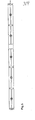
- Fig. 5 eine weitere.Ausführungsform, bei der mehrere Anordnungen gemäß Fig. 1 und 2 hintereinandergeschaltet sind und
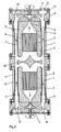
- Fig. 6 ein weiteres Ausführungsbeispiel mit zwei, an der Seite der Gasumlenkformteile zusammengefügten Anordnungen.
- In der in Fig. 1 und 2 gezeigten Anordnung wird das Lasergas in der Mitte des Längsrohres 1 mit großer Geschwindigkeit abgezogen und strömt dabei ohne Zwischenrohrleitung direkt in den aerodynamisch günstig geformten Einlauf 2 eines Radialverdichters 3. Die Achse des Radialverdichters 3 wird senkrecht zur Achse des aus den beiden Längsrohren 1 gebildeten Laserresonators angeordnet.
- Das Gas kommt nach Austritt aus dem Verdichter 3 durch den Diffusor 4 und die beiden spiralförmigen Gasumlenkelementen 5 ohne Rohrleitung direkt in den breiten Strömungskanal 6, der vorzugsweise den Wärmeaustauscher 7 einschließt und wird beiderseits wieder in das Laserrohr 1 umgelenkt bzw. zurückgeführt.
- Das eigentliche Laserrohr ist dabei in bekannter Weise aus einem isolierenden Material 8 wie Glas, Keramik oder Kunststoff hergestellt und in das Längsrohr 1 eingelassen. In einer bevorzugten Ausführungsform verbreitert sich das Laserrohr an der Stelle der ringförmigen Elektrode 9. Die Ringelektrode 9 liegt vorzugsweise nicht an der Wandung an, sondern ein Teil des Lasergases kann außen am Ring vorbei in den übrigen Abschnitt des Laserrohres 1 einströmen. Durch entsprechenden Abstand der Elektroden 9 von der Endplatte 10 des Lasers wird sichergestellt, daß die Gasentladung nicht gegen die Strömungsrichtung zu den Stirnplatten 10 des Lasersystems hin durchschlägt.
- In einer zweiten Version sind die beiden Endteile des gesamten Lasersystems zwischen einer Ebene, die etwa senkrecht durch die Elektroden 9 geht, und den Stirnplatten 10 aus isolierendem Material hergestellt. Die Stirnplatten sind isoliert, und es kann sich keine Gasentladung zwischen den Elektroden 9 und den Stirnplatten 10 ausbilden. Wenn man den Kühler 7 entsprechend verkürzt, kann man in diesem Fall den Abstand der Elektrode 9 zu den Stirnplatten 10 kleiner machen und das Laserrohr 1 noch besser ausnutzen. Selbstverständlich ist nicht nur der Kühler 7 von Wasser durchflossen, sondern auch die übrigen, von dem Lasergas erwärmten Teile werden mit Wasser oder einem anderen Kühlmittel gekühlt.
- Mit einem Verdichter von ca. 20 cm Laufraddurchmesser ergeben sich im Laserrohr bei 4,5 cm Rohrdurchmesser und 1,50 m Länge Strömungsgeschwindigkeiten von über 240 m/s; die Ausgangsleistung liegt bei annähernd 1 kW.
- Das System läßt sich jedoch leicht zu noch wesentlich höheren Leistungen bringen. Mit einem größeren Verdichter und größerem Rohrdurchmesser können Leistungen von über 3 kW erzielt werden. In Hinsicht auf gute Strahlqualität günstiger ist allerdings die Verwendung von zwei dünneren Laserrohren in paralleler oder gekreuzter Anordnung, wie in Fig. 3 und 4 dargestellt, anstelle eines Rohres mit entsprechend größerem Durchmesser. In beiden Fällen werden die beiden Rohre durch zwei (nicht eingezeichnete) Umlenkspiegel optisch verbunden.
- Selbstverständlich können auch mehrere Systeme der erfindungsgemäßen Art miteinander gekoppelt werden, und zwar parallel nebeneinander, übereinander oder hintereinander. Im Fall der Hintereinanderschaltung, wie es in Fig. 5 gezeigt ist, entfallen die Zwischenspiegel zur Kopplung der Systeme.
- Bei Verwendung doppelflutiger Turbinen kann man auch zwei Systeme in spiegelbildlicher Anordnung ohne Trennwand an' der Unterseite der Kühler 7 zusammenfügen.
- Die Erfindung läßt sich auch in der Weise realisieren, daß der Kühler auf der Saugseite und die Laserrohre auf der Druckseite angeordnet sind. In diesem Fall strömt das Lasergas nach Durchlaufen des Kühlers ohne Zwischenrohrleitung direkt in den aerodynamisch günstig geformten Einlauf des Radialverdichters, gelangt nach Austritt aus dem Verdichter und Durchströmen der Spirale (Leitbleche) direkt in einen als Laserrohr oder parallele Anordnung von Laserrohren ausgebildeten Strömungskanal, wird an den Enden dieses Strömungskanals umgelenkt und fließt wieder in den Kühler zurück.
- Besonders günstig und zur Erzeugung hoher Laserleistungen geeignet ist eine rotationssymmetrische Anordnung, bei der die Drehachse des Gebläserades und die Achsen der Laserrohre parallel zueinander verlaufen.
- Auch in dieser Anordnung, wie in Fig. 6 dargestellt, wird das Lasergas durch den entlang der Achse des Systems angeordneten Kühler 7 hindurch abgezogen, tritt durch einen Diffusor 4 und gegebenenfalls eine Spirale in Form von Gasleitblechen in einen ringförmigen Kanal 11, der in Laserrohre 1 unterteilt ist. Die-Laserrohre 1 müssen dabei selbstverständlich nicht den ganzen Querschnitt des ringförmigen Bereichs ausfüllen. Vielmehr kann das Gas durch eine begrenzte Anzahl von z.B. sechs symmetrisch angeordneten Laserrohren 1 hindurchgeleitet werden. Nach Durchlaufen der Laserrohre 1 wird das Gas in einem Formteil 12 wieder in den Kühler 7 zurückgeführt. Die Laserleistung wird durch geeignet geneigte Spiegel 13 von einem Rohr jeweils in das nächste umgelenkt, so daß sich auf diese Weise zwischen den Endspiegeln 14 eine Laserschwingung aufbauen kann. Ein Endspiegel ist in bekannter Weise als teildurchlässiger Spiegel ausgeführt; durch ihn kann die Laseremission austreten.
- Eine weitere Verdoppelung der Leistung erreicht man, wenn man zwei derartige Systeme mit gleicher Achse jedoch in spiegelbildlicher Anordnung auf der Seite des Umlenkformteils oder der Seite des Gebläserades zusammengefügt. Eine Verschmutzung der Spiegel wird vermieden, wenn man die Strömungsrichtung so wählt, daß die Gasbewegung, wie in Fig. 6 eingezeichnet, beiderseits von den Spiegeln wegführt.
- Selbstverständlich kann auch in diesem Fall das Gesamtsystem in Modulbauweise ausgeführt sein. Durch Bau des Zwischenteils aus isolierendem Material, teilweiser Isolierung des Umlenkteils und zusätzlicher Verwendung von je einer Hochspannungselektrode in der Mitte des Systems ist es außerdem möglich, die Elektroden 9 auf Erdpotential zu legen und am Anfang der Laserrohre anzuordnen, so daß die Laserrohre in ganzer Länge als aktive Bereiche genutzt werden können. Zur Verbesserung der Gasentladung (Zündung und Homogenität) können außerdem Zwischenelektroden vorgesehen werden.
Claims (11)
Priority Applications (1)
| Application Number | Priority Date | Filing Date | Title |
|---|---|---|---|
| AT83105118T ATE38301T1 (de) | 1982-12-11 | 1983-05-24 | Laseranordnung. |
Applications Claiming Priority (2)
| Application Number | Priority Date | Filing Date | Title |
|---|---|---|---|
| DE19823245959 DE3245959A1 (de) | 1982-12-11 | 1982-12-11 | Laseranordnung |
| DE3245959 | 1982-12-11 |
Publications (3)
| Publication Number | Publication Date |
|---|---|
| EP0111045A2 true EP0111045A2 (de) | 1984-06-20 |
| EP0111045A3 EP0111045A3 (en) | 1986-12-03 |
| EP0111045B1 EP0111045B1 (de) | 1988-10-26 |
Family
ID=6180471
Family Applications (1)
| Application Number | Title | Priority Date | Filing Date |
|---|---|---|---|
| EP83105118A Expired EP0111045B1 (de) | 1982-12-11 | 1983-05-24 | Laseranordnung |
Country Status (6)
| Country | Link |
|---|---|
| US (1) | US4624001A (de) |
| EP (1) | EP0111045B1 (de) |
| JP (1) | JPS59117184A (de) |
| AT (1) | ATE38301T1 (de) |
| CA (1) | CA1206574A (de) |
| DE (2) | DE3245959A1 (de) |
Cited By (4)
| Publication number | Priority date | Publication date | Assignee | Title |
|---|---|---|---|---|
| DE3926734A1 (de) * | 1989-08-12 | 1991-02-14 | Fraunhofer Ges Forschung | Gaslaser |
| DE3928540A1 (de) * | 1989-08-29 | 1991-03-14 | Tzn Forschung & Entwicklung | Laservorrichtung nach dem gastransportprinzip |
| DE3931082A1 (de) * | 1989-09-18 | 1991-03-28 | Tzn Forschung & Entwicklung | Gaslaser |
| WO1997014199A3 (de) * | 1995-10-10 | 1997-06-12 | Fraunhofer Ges Forschung | Laseranordnung, vorzugsweise hochleistungs-gaslaseranordnung |
Families Citing this family (13)
| Publication number | Priority date | Publication date | Assignee | Title |
|---|---|---|---|---|
| DE3600124A1 (de) * | 1986-01-04 | 1987-07-16 | Fortuna Werke Maschf Ag | Geblaese zum umwaelzen grosser gasmengen, insbesondere fuer hochleistungs-laser |
| DE3600126A1 (de) | 1986-01-04 | 1987-07-16 | Fortuna Werke Maschf Ag | Geblaese zum umwaelzen grosser gasmengen, insbesondere fuer hochleistungs-laser |
| DE3643735A1 (de) * | 1986-12-20 | 1988-07-07 | Tzn Forschung & Entwicklung | Gastransportlaser |
| DE8806785U1 (de) * | 1987-01-22 | 1988-10-20 | Gebr. Becker GmbH & Co, 5600 Wuppertal | Axialstromgaslaser, insbesondere CO↓2↓-Gaslaser |
| US4993037A (en) * | 1987-03-10 | 1991-02-12 | Amada Engineering & Service Co., Inc. | High speed axial flow gas laser generator |
| DE3734570C2 (de) * | 1987-10-13 | 1997-01-16 | Trumpf Gmbh & Co | Vorrichtung für einen längsgeströmten CO¶2¶-Leistungslaser |
| SE460570B (sv) * | 1987-10-13 | 1989-10-23 | Trumpf Gmbh & Co | Anordning foer en effektlaser |
| JPH02174281A (ja) * | 1988-12-27 | 1990-07-05 | Fanuc Ltd | ガスレーザ発振装置 |
| JPH02174282A (ja) * | 1988-12-27 | 1990-07-05 | Fanuc Ltd | ガスレーザ発振装置 |
| US4975925A (en) * | 1989-11-01 | 1990-12-04 | The Spectranetics Corporation | Unlubricated bearings for gas lasers |
| JP3022016B2 (ja) * | 1992-12-28 | 2000-03-15 | 松下電器産業株式会社 | 軸流形レーザ発振器 |
| JP4137961B2 (ja) * | 2006-07-13 | 2008-08-20 | ファナック株式会社 | ガスレーザ発振装置 |
| DE102007020427B4 (de) * | 2007-04-27 | 2012-10-04 | Trumpf Laser- Und Systemtechnik Gmbh | Laserentladungsrohr für einen Gaslaser und Herstellungsverfahren dafür |
Family Cites Families (9)
| Publication number | Priority date | Publication date | Assignee | Title |
|---|---|---|---|---|
| US3886477A (en) | 1968-10-29 | 1975-05-27 | United Aircraft Corp | Closed cycle device |
| US3886481A (en) | 1973-06-11 | 1975-05-27 | Gte Sylvania Inc | Power stabilized co' 2 'gas transport laser |
| US3984784A (en) | 1974-12-19 | 1976-10-05 | United Technologies Corporation | Expander open cycle gas dynamic laser |
| FR2296955A1 (fr) | 1974-12-31 | 1976-07-30 | Europ Propulsion | Laser a gaz dynamique |
| GB1569975A (en) | 1976-04-02 | 1980-06-25 | Atomic Energy Authority Uk | Gas lasers |
| US4099143A (en) * | 1977-01-14 | 1978-07-04 | Universal Laser Corp. | Gas recirculating stabilized laser |
| JPS5811110B2 (ja) | 1978-06-28 | 1983-03-01 | 株式会社日立製作所 | ガスレ−ザ発生装置 |
| JPS55113391A (en) | 1979-02-21 | 1980-09-01 | Hitachi Ltd | Gas flow type laser device |
| EP0065761B1 (de) * | 1981-05-29 | 1985-11-27 | Battelle-Institut e.V. | Laseranordnung |
-
1982
- 1982-12-11 DE DE19823245959 patent/DE3245959A1/de not_active Withdrawn
-
1983
- 1983-05-24 DE DE8383105118T patent/DE3378340D1/de not_active Expired
- 1983-05-24 EP EP83105118A patent/EP0111045B1/de not_active Expired
- 1983-05-24 AT AT83105118T patent/ATE38301T1/de not_active IP Right Cessation
- 1983-12-08 CA CA000442832A patent/CA1206574A/en not_active Expired
- 1983-12-09 JP JP58232640A patent/JPS59117184A/ja active Pending
- 1983-12-12 US US06/560,377 patent/US4624001A/en not_active Expired - Fee Related
Cited By (4)
| Publication number | Priority date | Publication date | Assignee | Title |
|---|---|---|---|---|
| DE3926734A1 (de) * | 1989-08-12 | 1991-02-14 | Fraunhofer Ges Forschung | Gaslaser |
| DE3928540A1 (de) * | 1989-08-29 | 1991-03-14 | Tzn Forschung & Entwicklung | Laservorrichtung nach dem gastransportprinzip |
| DE3931082A1 (de) * | 1989-09-18 | 1991-03-28 | Tzn Forschung & Entwicklung | Gaslaser |
| WO1997014199A3 (de) * | 1995-10-10 | 1997-06-12 | Fraunhofer Ges Forschung | Laseranordnung, vorzugsweise hochleistungs-gaslaseranordnung |
Also Published As
| Publication number | Publication date |
|---|---|
| ATE38301T1 (de) | 1988-11-15 |
| DE3378340D1 (en) | 1988-12-01 |
| EP0111045B1 (de) | 1988-10-26 |
| EP0111045A3 (en) | 1986-12-03 |
| JPS59117184A (ja) | 1984-07-06 |
| DE3245959A1 (de) | 1984-06-14 |
| US4624001A (en) | 1986-11-18 |
| CA1206574A (en) | 1986-06-24 |
Similar Documents
| Publication | Publication Date | Title |
|---|---|---|
| EP0111044B1 (de) | Laseranordnung | |
| EP0111045B1 (de) | Laseranordnung | |
| EP0065761B1 (de) | Laseranordnung | |
| DE3546280C2 (de) | ||
| EP0109025A2 (de) | Gaslaser | |
| DE2456687A1 (de) | Koaxialer gaslaser mit geschlossenem kreislauf und mehrfachrohr | |
| CH676299A5 (de) | ||
| DE3716873C2 (de) | ||
| EP0427229A2 (de) | Laser | |
| DE3335410A1 (de) | Hochleistungslaser | |
| DE3643735C2 (de) | ||
| US8814522B2 (en) | Cross-flow fan impeller for a transversley excited, pulsed, gas discharge laser | |
| DE3330238A1 (de) | Hochleistungslaser | |
| DE3734570C2 (de) | Vorrichtung für einen längsgeströmten CO¶2¶-Leistungslaser | |
| DE3305173A1 (de) | Durch zwangsluftstroemung kuehlbarer uv-strahler mit einer langbogenentladungslampe | |
| EP0952656A1 (de) | Überströmkanäle eines Generators mit direkter Saugkühlung | |
| EP0089974B1 (de) | Laseranordnung | |
| DE2442325A1 (de) | Querstromkuevette fuer fluessigkeits-, dampf- oder gaslaser | |
| DE112014005974T5 (de) | Gaslaser-Oszillationsvorrichtung vom orthogonalen Anregungstyp | |
| DE1764359B2 (de) | Keramische entladungsroehre fuer einen gaslaser | |
| DE3923624A1 (de) | Verfahren zum betrieb eines gaslasers, insbesondere eines co(pfeil abwaerts)2(pfeil abwaerts)-lasers, mit gasstroemung quer zu seiner optischen achse und gaslaser zur durchfuehrung des verfahrens | |
| DE3121372C2 (de) | ||
| DE3928540C2 (de) | Laservorrichtung nach dem Gastransportprinzip | |
| DE3923625A1 (de) | Verfahren zum betrieb eines gaslasers, insbesondere eines co(pfeil abwaerts)2(pfeil abwaerts)-lasers, mit gasstroemung quer zu seiner optischen achse und gaslaser zur durchfuehrung des verfahrens | |
| CN1592009A (zh) | 圆形金属腔转流激光器 |
Legal Events
| Date | Code | Title | Description |
|---|---|---|---|
| PUAI | Public reference made under article 153(3) epc to a published international application that has entered the european phase |
Free format text: ORIGINAL CODE: 0009012 |
|
| AK | Designated contracting states |
Designated state(s): AT BE CH DE FR GB IT LI NL SE |
|
| PUAL | Search report despatched |
Free format text: ORIGINAL CODE: 0009013 |
|
| AK | Designated contracting states |
Kind code of ref document: A3 Designated state(s): AT BE CH DE FR GB IT LI NL SE |
|
| 17P | Request for examination filed |
Effective date: 19870515 |
|
| 17Q | First examination report despatched |
Effective date: 19880330 |
|
| RAP1 | Party data changed (applicant data changed or rights of an application transferred) |
Owner name: TZN FORSCHUNGS- UND ENTWICKLUNGSZENTRUM UNTERLUESS |
|
| ITF | It: translation for a ep patent filed | ||
| GRAA | (expected) grant |
Free format text: ORIGINAL CODE: 0009210 |
|
| AK | Designated contracting states |
Kind code of ref document: B1 Designated state(s): AT BE CH DE FR GB IT LI NL SE |
|
| REF | Corresponds to: |
Ref document number: 38301 Country of ref document: AT Date of ref document: 19881115 Kind code of ref document: T |
|
| GBT | Gb: translation of ep patent filed (gb section 77(6)(a)/1977) | ||
| REF | Corresponds to: |
Ref document number: 3378340 Country of ref document: DE Date of ref document: 19881201 |
|
| ET | Fr: translation filed | ||
| PLBE | No opposition filed within time limit |
Free format text: ORIGINAL CODE: 0009261 |
|
| STAA | Information on the status of an ep patent application or granted ep patent |
Free format text: STATUS: NO OPPOSITION FILED WITHIN TIME LIMIT |
|
| 26N | No opposition filed | ||
| ITTA | It: last paid annual fee | ||
| PGFP | Annual fee paid to national office [announced via postgrant information from national office to epo] |
Ref country code: SE Payment date: 19920413 Year of fee payment: 10 |
|
| PGFP | Annual fee paid to national office [announced via postgrant information from national office to epo] |
Ref country code: CH Payment date: 19920428 Year of fee payment: 10 |
|
| PGFP | Annual fee paid to national office [announced via postgrant information from national office to epo] |
Ref country code: AT Payment date: 19920429 Year of fee payment: 10 |
|
| PGFP | Annual fee paid to national office [announced via postgrant information from national office to epo] |
Ref country code: FR Payment date: 19920430 Year of fee payment: 10 |
|
| PGFP | Annual fee paid to national office [announced via postgrant information from national office to epo] |
Ref country code: GB Payment date: 19920508 Year of fee payment: 10 |
|
| PGFP | Annual fee paid to national office [announced via postgrant information from national office to epo] |
Ref country code: BE Payment date: 19920527 Year of fee payment: 10 |
|
| PGFP | Annual fee paid to national office [announced via postgrant information from national office to epo] |
Ref country code: NL Payment date: 19920531 Year of fee payment: 10 |
|
| PG25 | Lapsed in a contracting state [announced via postgrant information from national office to epo] |
Ref country code: GB Effective date: 19930524 Ref country code: AT Effective date: 19930524 |
|
| PG25 | Lapsed in a contracting state [announced via postgrant information from national office to epo] |
Ref country code: SE Effective date: 19930525 |
|
| PG25 | Lapsed in a contracting state [announced via postgrant information from national office to epo] |
Ref country code: LI Effective date: 19930531 Ref country code: CH Effective date: 19930531 Ref country code: BE Effective date: 19930531 |
|
| BERE | Be: lapsed |
Owner name: TZN FORSCHUNGS- UND ENTWICKLUNGSZENTRUM UNTERLUSS Effective date: 19930531 |
|
| PG25 | Lapsed in a contracting state [announced via postgrant information from national office to epo] |
Ref country code: NL Effective date: 19931201 |
|
| NLV4 | Nl: lapsed or anulled due to non-payment of the annual fee | ||
| GBPC | Gb: european patent ceased through non-payment of renewal fee |
Effective date: 19930524 |
|
| PG25 | Lapsed in a contracting state [announced via postgrant information from national office to epo] |
Ref country code: FR Effective date: 19940131 |
|
| REG | Reference to a national code |
Ref country code: CH Ref legal event code: PL |
|
| REG | Reference to a national code |
Ref country code: FR Ref legal event code: ST |
|
| EUG | Se: european patent has lapsed |
Ref document number: 83105118.0 Effective date: 19931210 |
|
| PGFP | Annual fee paid to national office [announced via postgrant information from national office to epo] |
Ref country code: DE Payment date: 19950418 Year of fee payment: 13 |
|
| PG25 | Lapsed in a contracting state [announced via postgrant information from national office to epo] |
Ref country code: DE Effective date: 19970201 |