EP0111066A2 - Elektronische Tonsignalverarbeitungsschaltung - Google Patents
Elektronische Tonsignalverarbeitungsschaltung Download PDFInfo
- Publication number
- EP0111066A2 EP0111066A2 EP83108976A EP83108976A EP0111066A2 EP 0111066 A2 EP0111066 A2 EP 0111066A2 EP 83108976 A EP83108976 A EP 83108976A EP 83108976 A EP83108976 A EP 83108976A EP 0111066 A2 EP0111066 A2 EP 0111066A2
- Authority
- EP
- European Patent Office
- Prior art keywords
- audio
- signal
- output
- audio signal
- circuit
- Prior art date
- Legal status (The legal status is an assumption and is not a legal conclusion. Google has not performed a legal analysis and makes no representation as to the accuracy of the status listed.)
- Granted
Links
- 230000005236 sound signal Effects 0.000 title claims abstract description 85
- 230000004044 response Effects 0.000 claims abstract description 18
- 238000001914 filtration Methods 0.000 claims description 12
- 230000003111 delayed effect Effects 0.000 claims description 7
- 230000003247 decreasing effect Effects 0.000 claims 6
- 230000004075 alteration Effects 0.000 abstract description 7
- 230000006835 compression Effects 0.000 abstract description 2
- 238000007906 compression Methods 0.000 abstract description 2
- 239000003990 capacitor Substances 0.000 description 20
- 238000010586 diagram Methods 0.000 description 5
- 230000000694 effects Effects 0.000 description 5
- 210000003127 knee Anatomy 0.000 description 4
- 238000000034 method Methods 0.000 description 3
- 230000008569 process Effects 0.000 description 3
- 230000008901 benefit Effects 0.000 description 2
- 230000008859 change Effects 0.000 description 2
- 230000001419 dependent effect Effects 0.000 description 2
- 230000004048 modification Effects 0.000 description 2
- 238000012986 modification Methods 0.000 description 2
- 238000005096 rolling process Methods 0.000 description 2
- 238000001228 spectrum Methods 0.000 description 2
- 230000002459 sustained effect Effects 0.000 description 2
- 230000001052 transient effect Effects 0.000 description 2
- 230000002238 attenuated effect Effects 0.000 description 1
- 125000004122 cyclic group Chemical group 0.000 description 1
- 230000001934 delay Effects 0.000 description 1
- 238000002592 echocardiography Methods 0.000 description 1
- 230000002708 enhancing effect Effects 0.000 description 1
- 238000002474 experimental method Methods 0.000 description 1
- 239000011435 rock Substances 0.000 description 1
- 238000000926 separation method Methods 0.000 description 1
Images




Classifications
-
- G—PHYSICS
- G10—MUSICAL INSTRUMENTS; ACOUSTICS
- G10H—ELECTROPHONIC MUSICAL INSTRUMENTS; INSTRUMENTS IN WHICH THE TONES ARE GENERATED BY ELECTROMECHANICAL MEANS OR ELECTRONIC GENERATORS, OR IN WHICH THE TONES ARE SYNTHESISED FROM A DATA STORE
- G10H3/00—Instruments in which the tones are generated by electromechanical means
-
- G—PHYSICS
- G10—MUSICAL INSTRUMENTS; ACOUSTICS
- G10K—SOUND-PRODUCING DEVICES; METHODS OR DEVICES FOR PROTECTING AGAINST, OR FOR DAMPING, NOISE OR OTHER ACOUSTIC WAVES IN GENERAL; ACOUSTICS NOT OTHERWISE PROVIDED FOR
- G10K15/00—Acoustics not otherwise provided for
- G10K15/08—Arrangements for producing a reverberation or echo sound
- G10K15/12—Arrangements for producing a reverberation or echo sound using electronic time-delay networks
Definitions
- This invention is directed to devices which alter the electrical audio signals, and more particularly to devices for producing controlled distortion in audio output signals and for enhancing the tonal quality thereof.
- one prior art device has a distortion generator or a distortion compressor stage followed by a filter with a roll-off or attenuation with increased frequency, along with means to adjust either the amount (steepness) of the roll-off, or the point (knee) of the roll-off.
- the filter in such a device is very crude.
- the adjustment means requires the operator to experiment with different settings or combinations of settings in order to define a desirable sound,. and even then the device qs limited in the quality of sound which it is capable of producing.
- the arrangement just described does little if anything to tailor or enhance the character or quality of the tone of the signal produced by the distortion generator or compressor stage.
- An object of the invention is to all controlled distortion to an audio signal to change the dynamics or sustain characteristics of an audio signal, and to alter the tonal quality of the audio signal.
- a further object of the invention is to add reverberation to an audio signal such that the resultant signal has superior reverberation characteristics.
- a mid band pass filter receives an electrical audio input signal and provides the output to a distortion amplifier which receives the output ! of the mid band pass filter and adds higher harmonic audio signals to the received signal, compresses it further, and alters the waveform.
- a complex filter receives the output of the distortion amplifier and provides an output signal having enhanced tonal qualities.
- the complex filter has a roll-off of increased attentuation with increased frequency range, a boost in the low frequency range, a dip in the upper portion oj the low frequency range, a dip in the mid audio frequency range, a dip followed by a peak in the upper frequency portion of the mid audio frequency range, followed by a roll-off of increased attenuation with increased frequency in the upper audio frequency range.
- a high pass audio filtering circuit receives an electrical audio input signal and provides an output signal to a compressor circuit which produces an output signal having increased sustain.
- a complex filter with characteristics as described above may be provided after the compressor circuit.
- a compressor circuit receives an audio signal and produces an output signal having increased sustain, a mid pass filter receives this signal, and the filtered signal is provided to a distortion amplifier which adds more compression and higher audio harmonic signals.
- a complex filter having characteristics as described above, may be provided after the distortion amplifier.
- a timed turn on gate receives a main audio signal and gates this signal to an analog shift register device only after this signal exceeds a certain signal level for a certain time period.
- the analog shift register provides delayed output signals at a plurality of staggered delay taps.
- At least one summing device receives the output signals at several delay taps and outputs a signal having reverb characteristics or delay ("echo") components.
- an analog shift register receives a main audio signal and provides delayed outputs at a plurality of staggered delay taps.
- An output delay circuit receives an output signal from one of the staggered delayed taps, preferably the last in the series, and delays the received signal a time period substantially different from the delay time period between any two of the adjacent staggered delay taps.
- Two summing devices receive output signals from the delay taps, and one of the summing devices receives the output from the output delay circuit. By summing the signals inputted thereto, the summing devices provide two different channels of audio output signals having different delay components.
- the output delay circuit following the analog shift register provides additional reverberation components to the resultant output signal, which is different from the sound obtained by using a single analog shift register.
- the term “low” when used in conjunction with low pass filters and the like is intended to refer to a range-starting at about 50 Hz and ending at about 250 Hz to 800 Hz.
- the word “middle” or “mid” is intended to refer to the range starting at about 250 Hz to 800 Hz and ending at about 2 KHz to 5 KHz.
- the word “high” is intended to refer to the range starting about 2 KHz to 5 KHz and ending somewhere in the upper audio frequency spectrum.
- the compressor as described herein is intended to refer to a device which compresses the intensity range of the output signal as compared to the range of the input signal, and more particularly to a device which amplifies weak signals and attenuates strong signals to produce a smaller output range for a given input range.
- the distortion amplifier is intended to refer to a device which functions as a linear amplifier up to a certain point of input signal level and then clips above that certain level in order to produce controlled distortion. In the preferred embodiment., the distortion amp functions to cause intermodulation of the input signals and to produce high harmonics of the low range and mid range audio content of the input signal, generally independently of the high range content of the input signal.
- the doubler (synthetic doubler) produces an output signal which varies in pitch from its input singal, so that its output signal simulates an instrument different from the instrument providing the input signal.
- the output of the doubler is combined with the input by a summer or mixer the result is like two separate instruments.
- the preferred embodiment according to the invention has two main portions: a controlled distortion and tone alteration and sustain alteration portion, and a reverberation portion.
- the portion.of the preferred embodiment which is directed to controlled distortion tone alteration and sustain operates in one of four modes, as controlled by a selector switch.
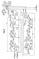
- a different combination of filters and -devices are connected serially in a chain after a buffer amp 10 and high pass filter 11 as shown in Figure 1.
- the filter 11 increases the mid and some of the high range part of the input signal which decay faster, causing the compressor to react more to the mid range part of the signal than to the low range,part of the signal. This allows the compressor to maintain the mid range at a more constant level as a note decays, which is more pleasing when heard directly, and is important when its output is connected to the distortion amp 16 and a complex filter 17.
- the chain consists of the compressor 12 with the high end EQ boost 12A, a high pass filter 13 and the complex filter 17.
- the chain consists of the compressor 12 without the high end EQ boost 12A, the high pass filter 13 and the complex filter 17.
- the chain consists of the compressor 12 without the high end EQ boost 12A, and a low boost EQ 15.
- the distortion amp 16 is used for adding substantial controlled distortion.
- the mid band pass filter 14 reduces the high and low signal content before the signal goes through the distortion amp 16. Rolling off the highs results in less noise at the output of the distortion amp and reduces the amount of highs from the input signal heard after the distortion amp 16. This is important because in this substantial distortion mode it is important that the high end contact of the output signal be made up primarily of high harmonics produced by distorting the mid range portion of the signal which are of long duration, rather than by the natural high harmonics contained in the input signal which are of short duration.
- the high pass filter 11 is modified in this mode by opening the switch 100 which causes the filter to level off at a lowered frequency thus providing less high end content. The rolling off of the lows is important as this reduces modulation of the output signal by the low end content of the input signal. Actually, the low signal content is reduced twice; once at the high pass filter 11 after the buffer am p 10, and again at the mid band pass filter 14.
- the compressor 12 receives a wide amplitude range of signals and outputs an output signal having a relatively narrow amplitude range.
- the compressor 12 is designed so that its output is fixed at a good level for generating harmonics within the distortion amplifier 16. Therefore, one advantage of having the compressor 12 in front of the distortion amp 16 is so that the harmonics generated by the distortion amp 16 can be controlled by the operation of the compressor 12.
- One aspect of the invention is directed to minimizing the difference between the initial output of the distortion amplifier 16 and the subsequent sustained output of the distortion amplifier.
- a compressor 12 is used to prevent the signal from dying out or decaying as quickly and keeps the signal near a maximum output level for a certain time period. This signal is fed into the distortion amplifier 16 or distortion generator which generates harmonics.
- the mid band pass filter 14 in front of the distortion amplifier 16 is fairly important in obtaining a distorted musical sound having good waveform quality, as is the compressor 12 bi p ass EQ 11.
- the complex filter-17 which receives the output of the distortion device, processes this output into an output signal having excellent tonal qualities. Without this filter, the output would be both "harsh” and “muddy” in tonal quality.
- the gain of an operational amplifier in the compressor state 12 will be reduced, thereby cancelling some of the effect of the compressor unit 12 and reducing the level of the signal going into the distortion amp 16.
- the distortion amp 16 will not stay in the distortion state quite as long. Each time a note is played on the guitar, distortion will occur, but only for a brief time period.
- the distortion amplifier 16 produces more high harmonics as the amp 16 is driven harder. Therefore, when the distortion amp 16 is not driven hard, lesser high harmonics are produced.
- a high end EQ boost 12A high pass filter
- the generated highs will diminish as the distortion amp 16 returns to the linear range of operation and no longer outputs a distorted signal. Since the distortion amp is no longer producing as much high end, a high end EQ boost 12A in the compressor is switched in this second mode. The high end produced will compensate for the fact that the distortion amp 16 is not producing as much high end, resulting in approximately the same amount of high signal content, but without as much distortion. This mode of operation may be desirable for guitar players who desire only a slight amount of distortion for pop music, instead of heavy rock and roll type sustained distortion.
- the importance of having the high end EQ boost 12A before the distortion amp 16 can be illustrated by considering what sound would result by having a high end EQ boost after instead of before a distortion amp. Then the high harmonics synthetically generated by the distortion amp would also be amplified or boosted, and the distorted tones would be boosted, and the true guitar sounds would be masked too much by the distorted guitar tones.
- the boost has substantially no effect on the high harmonics that the distortion amp produces because the output of the distortion amp is more dependent on the mid range content of the signal than the high range. Therefore, it is important that the high end EQ boost 12A associated with the compressor 12 be placed in front of the distortion amp 16 when the distortion amp is driven at lowered signal levels. This output is then processed by the complex filter 17 to improve its tonal qualities.
- the chain consists of the compressor 12 without the high end EQ boost 12A, a high pass filter 13 and the complex filter 17.
- This operational mode might be used by musicians who desire a clean sound without controlled distortion.
- the distortion amplifier 16 used in the first operational mode outputs a relatively large amount of high end signal content by adding high harmonics. Since the distortion amplifier is not used in this operational mode, the high pass filter 13 increases the higher harmonic content of the signal and thus compensates for the absence of the distortion amplifier 16.
- the complex filter 17 was designed primarily to process the output of the distortion amplifier 16 but is used in this mode to make the tone more similar to that of the first and second operational mode.
- the complex filter 17 functions so that its output has a relatively large amount of low end and mid range signal content and rolls off dramatically at its upper end due to the large high end signal content produced when the distortion amp is being used.
- a simpler high pass filter 13 is provided in cascade with the complex filter 17. The high pass filter 14 will compensate somewhat for the bass heavy response of the complex filter 17.
- a simpler high pass filter 13 is provided in cascade with the complex filter 17.
- the high pass filter 14 will compensate somewhat for the bass heavy response of the complex filter 17.
- the device Since the complex filter 17 has a peak in the mid range at about 500 Hz with a dip at 250Hz and 1.6 KHz, the device will process the signal from a rather toneless guitar into a signal with enhanced tonal qualities in the same way the good stringed instruments with good tonal qualities have heavy response areas in the mid range. For guitars which already have good tonal response in the mid range, some additional mid range tone will be obtained.
- the chain consists of the compressor 12 without the high end EQ boost 12A, and a low end EQ boost 15.
- This operational mode omits the distortion amplifier 16 and complex filter 17 present in other operational modes, and is primarily for keyboard instruments or for jazz guitarists who want a truer sound without substantial emphasis or de-emphasis of the tonal qualities of the musical instrument.
- the lower end of the audio frequency spectrum is boosted by the low end lost through the high pass filter 11.
- total compensation is not achieved, since if the high pass filter 13 and low pass filter 15 are superimposed, the resultant filter would be flat from 50 to 400 Hz and then climb to about 5 KHz where it would flatten out.
- Buffer amplifier 10 comprising integrated circuit IC 101A receives an electrical input signal from a musical instrument or any other device producing audio signals through monaural connector CN 102 and resistor R 101.
- the output of the buffer amplifier 10 is provided .to a high pass filter circuit 11 comprising resistors R 102 and R 103, capacitor C 103 and switch SW 100.
- Switch SW 100 provides a means to adjust the point of the roll-off or knee between one frequency-position of about 5 KHz (for "clean” sounds) and a higher frequency position (for “distorted” sounds).
- the high pass filter 11 has a roll-off of increased attenuation with a decrease in frequency of about 6 db per octave.
- the gain of the mid-range is higher by about 6 db. Accordingly, with the increase in gain the large signal inputted to the op amp IC 101B will probably push it into distortion at all times.
- SW 100 is mechanically tied to SW 101, so that SW 100 is open only when SW 101 is in its uppermost position. In this position the device operates in the first mode, i.e. with the mid band pass filter, without the high end EQ boost 12A in the compressor stage 12.
- the output of the high pass filter 11 is provided to a compressor circuit 12.
- the compressor circuit 12 amplifies weak signals and attenuates strong signals to produce a smaller amplitude range compared to the amplitude range of its input.
- the compressor circuit comprises essentially an amplifier IC 101B and an FET transistor Q 101 which serves to compress or reduce the amplitude range of the signal appearing at the input of amplifier IC 101B.
- the output of the op amp 1C 101 B goes through two resistors R 169 and R 170 to ground.
- the signal between those resistors goes through a diode D 101 to the gate of FET Q 101.
- the resistance for the FET goes up and cuts down the feedback of the op amp.
- diode D 119 which serves to limit the amount of compressing that the FET can perform.
- diode D 119 effectively reduces the resistance across R 170. As soon as the signal gets above the threshold level of this diode D 119, the signal is passed to ground.
- the FET gate increases resistance until it gets to a certain point. At'that point the signal level across the gate of the FET will not increase. If the op amp signal increases, the FET stops compressing at a certain point and intentionally lets the signal build up going through the op amp.
- the signal is normally compressed, and the peaks are held to just below where the op amp is starting to clip.
- the signal immediately following is amplified up to this same point as C 106 discharges within about 50 milliseconds or less. Any extra signal will not be compressed since the diode D 119 prevents the signal at the FET from surpassing a certain limit.
- the peak of the signal will cause distortion of the op amp TC 101 B, which is acceptable because distortion is a widely understood. indicator that the input signal is too large, and the musician will likely, reduce the volume of the instrument. Also, the clipping (distortion) of peaks is often accepted as normal for guitar amplifiers.
- Compressor circuit 12 also includes a switchable high end EQ boost portion 12A comprising resistors R 109, R 110 and capacitor C 105.
- switch S W 101 the operation of which will be described in greater detail below
- the high end EQ boost portion 12A is switched into the IC 101 B feedback loop, so that the high pass filter with a knee at about 2 KHz is added to the compressor circuit 12.
- the high pass filter 13 comprises a resistor R 111 and capacitor C 107 and is connected in the circuit when the switch SW 101 is in the third and fourth positions.
- the filter is ineffective in the fourth position, however, due to the high input impedence of filter 15.
- the mid band pass filter 14 comprises resistors R 112 and R 113 and capacitors C 108 and C 109.
- the mid band pass filter 14 receives its input from the output of the compressor circuit 12 and outputs a filtered signal which is fed to the input of distortion amp 16.
- Distortion amp 16 comprises an integrated circuit IC 102A, and a feedback loop comprising diodes D 102 through D 105 and resistor R 114.
- the diodes serve to clip both the negative and positive going amplitudes of the output voltage to produce distortion when the input signal level is above a certain point. However below that certain point, the distortion amplifier 16 functions essentially as a linear amplifier.
- the output of distortion amplifier 16 is provided to a terminal of switch SW 101.
- Switch SW 101 is a 10 terminal, four position slide switch having right and left slide members which are insulated from each other but which move together by a manual switching actuator. Each of the right and left slide members connect two adjacent terminals at a time. Thus, when the switch is in the extreme upper position, the upper two terminals on each side will be connected to each other. In the upper position, the controlled distortion portion of the preferred embodiment operates in the first mode (i.e. the middle chain with the mid band pass filter). In this position the output of the distortion amp 16 is connected to the input of the complex filter 17, and the EQ portion 12A of circuit 12 is not Connected. When switch SW 101 is connected in the second uppermost position, the condition of the device is essentially the same as just described, except that the equalization portion 12A is connected in circuit with compressor section 12, so that the controlled distortion portion of the preferred embodiment operates in the second mode.
- the equalization portion 12A is connected in circuit with compressor section 12, so that the controlled distortion portion of the preferred embodiment operates in the second mode.
- the complex filter 17 comprises three substantially similar cascaded amplifier and filter stages having different value resistors and capa - citors which define different frequency response characteristics for each of the stages and a passive filter stage providing a lower pass filter at the beginning.
- the resultant frequency response is that shown in Figure 1, i.e.
- the low pass filter 15 as shown in Figure 3 comprises an amplifier IC 104B, input resistor R 130 and a feedback loop comprising resistors R 131, R 132 and capacitor C 117.
- the frequency response of the low pass filter 15 is shown in Figure 1 and has a generally flat response below 50 Hz, with increased attenuation with increased frequency between 50 Hz and 400 Hz, with a generally flat response above 400 Hz.
- low pass filter 15 is switched into the circuit when SW 101 is in the lowermost position, i.e. the fourth operational mode.
- the portion of the preferred embodiment which is directed to reverberation comprises a doubling circuit 18, a timed turn on gate 19, an analog shift register bucket brigade device 20 with delay taps including its associated input buffer amp and filter circuit 20A, an output delay circuit 21, an output summing and amplifier circuit 22, and an output amplifier and mixing circuit 23.
- This portion of the preferred embodiment operates in one of three modes to provide doubling alone, reverb alone, or both doubling and reverb.
- the timed turn on gate 19 receives a main audio signal which is fed into amplifier IC 102B.
- Amplifier IC 102B in conjunction with amplifier IC 105A and associated resistors R 133 through R 140, capacitors C 118 through C 120 and diodes D 106 through D 110, will effect switching of FET transitor Q 102 (to gate the main audio signal to IC 105B) about 20 milliseconds after a main audio signal of sufficient magnitude is present on the main signal line.
- the main audio signal that is gated comes through resistor R 141.
- Capacitor C 120 in conjunction with R 139, sets the release time of the timed turn on gate which is a few milliseconds. Thus, if the signal voltage suddenly drops, the voltage across the capacitor C 120 will not disappear immediately, but will bleed off gradually through resistor R 139. Therefore, the FET will not clamp down shut suddenly but instead will slowly turn off so that the sound into the reverb does not end abruptly.
- the doubling circuit 18 essentially functions to simulate a second instrument which is slightly off key and slightly out of time with an initial instrument. This is done by cyclicly varying the pitch of the initial instrument signal back and forth about its nominal pitch. For example, if the nominal pitch of the initial instrument signal is an F note then the doubler will output a sharp F note for a while and then a flat F note for a while followed by a sharp F note again and so on.
- Cyclic pitch variation can be achieved by inputting the initial instrument signal into an analog delay device and then varying the clock frequency of the clock which drives the delay device.
- the delay device is a bucket brigade
- the bucket brigade receives an initial instrument signal and shifts the signal within the brigade from bucket to bucket at speed determined by the frequency of the clock which drives the bucket brigade.
- the pitch of the signals passed by the buckets can be varied.
- the pitch will reduce.
- the resultant delay of the bucket brigade will be delayed further and further until eventually the output would be minutes behind its input.
- the pitch is increased and then reduced and so on in a cyclical manner. Of course the delay will vary within the range of about 15 to 20 milliseconds.
- the doubling circuit 18 comprises essentially two circuit portions: .an analog delay portion 18A and a delay clock portion 18B.
- the analog delay portion 18A comprises a bucket brigade device IC 110 which has an input buffer amp IC 106A, and an output buffer amp IC 106B, each having associated resistors and capacitors as shown.
- the bucket brigade IC 110 at its pins 2 and 6 receives a series of clock pulses of opposite phase from 1C 109. 1C 108 and 109 create a high frequency clock whose frequency varies about a nominal rate.
- a low frequency oscillator comprising 1C 107 A and B, along with associated resistors and capacitors, provides a triangle waveform signal of frequency about .5 H 2 to pin 3 of 1C 109.
- 1C 108 and 109 will produce clock pulses of slowly varying frequency.
- the bucket brigade will respond to these clock pulses to cyclicly very the pitch of its output signal to either side of the pitch of its input signal.
- the output of the doubling circuit will thus simulate-a second instrument slightly off key and out of time with an instrument whose signal is inputted to the doubling circuit.
- Switch 201 is an eight terminal three position slide switch having an upper sliding member which engages two adjacent terminals at a time, and a lower sliding member which also engages two terminals at a time and moves in conjunction with the upper sliding member. The sliding members are moved by manual switch actuating element.
- the switch actuator When the switch actuator is'on the extreme left, the reverberation portion of the preferred embodiment provides a doubling output but no reverb output to the output mixers.
- the switch actuator is in the middle position, the reverberation portion of the preferred embodiment will provide both a doubling component and a reverberation component to the output mixers.
- the switch actuator is on the extreme right, the reverberation portion of the circuit will provide a reverberation signal but no doubling component to the output mixers.
- the bucket brigade circuit 20 When switch 201 is in either the middle or extreme right position, the bucket brigade circuit 20 will receive a signal at the input of its buffer amplifier and filter circuit portion 20A.
- the buffer amplifier and filter circuit portion comprises two integrated circuits IC 203A and IC 203B, and associated resistors and capacitors, and provides an amplified and filtered signal to pin 12 of the bucket brigade device IC 206.
- the integrated circuit IC 206 is an analog shift register having 6 output delay taps at pins 4-9 thereof.
- Integrated circuit IC 208 is an analog shift register clock generator/driver which drives both integrated circuits IC 206 and IC 207.
- the period of the switching of the timer is dependent upon the circuit values of resistors R 254, R 255 and capacitor C 228.
- the bucket brigade IC 206 receives an input signal at pin 12 and provides this signal at different delay periods to the output delay taps (pins 4-9).
- the delay ' between adjacent delay taps is about 15 to 40 milliseconds, so that the input signal is outputted at the first delay tap (pin 9) about 25 milliseconds after it is received at pin 12.
- the signal is outputted at the last delay tap (pin 4) about 150 milliseconds after it is received at input pin 12 of IC 206.
- the output of the last delay tap (pin 4) is provided to pin 3 of an additional output delay integrated circuit chip IC 207, which is also an analog shift register like 1C 206, but with fewer stages.
- IC 207 at pins 7 and 8, provides a delayed output about 50 milliseconds after it receives an input at pin 3..
- output delay taps 4-9 of bucket brigade IC 206 and delay taps 7 and 8 of IC 207 are fed into a resistor summing network comprising resistors R 245 through R 251.
- the outputs of alternate pins 4, 6 and 8 are summed on the lower output line (left channel), whereas the outputs of alternate pins 5, 7 and 9 are summed on the upper output line (right channel).
- the output of the additional output delay chip IC 207 is fed to the upper output line only.
- the output of the upper output line (right channel) is fed to the input of a right output amplifier and filter comprising integrated circuits IC 204A and IC 204B, associated resistors R 225 through R 230, and capacitors C 216 through C 220.
- the output of this right output amplifier and filter appearing at pin 7 of IC 204B is connected to a resistor R 204 at the input of output amplifier and mixing circuit 23.
- the output of the lower line of summing resistors (left channel) is fed to the left output amplifier and filter circuit comprising IC 205A and IC 205B, associated resistors R 231 through R 236, and capacitors C 221 through C 225.
- the output of the left output amplifier and filter circuit appears at pin 7 of IC 205B and is connected to resistor R 209 at the input of output amplifier and mixing circuit 23.
- the output amplifier and mixing circuit 23 comprises essentially two different, but substantially identical, output amplifier and mixing circuits 23A and 23B.
- the upper output amplifier and mixing circuit 23A comprises four input summing resistors R 202 through R 205 and an amplifier mixer IC 202A.
- the lower output amplifier and mixing circuit 23B comprises four input summing resistors R 206 through R 209 and an amplifier mixer IC 202B.
- the main signal from the controlled distortion and tone alteration portion of the circuit always appears at the left side of input summing resistors R 202 and R 206.
- switch SW 201 When switch SW 201 is in the middle or right position, reverberation signals will appear at the left side of input summing resistors R 204 and R 209.
- a doubling signal will appear at the left side of input summing resistors R 203 and R 207 when switch SW 201 is in either the left or middle position, but not when SW 201 is in the right position.
- the main audio signal will appear at the left side of resistors R 203 and R 207 in place of the doubling signal to compensate for the absence of the doubling signal.
- auxiliary input signal can be inputted to connector CN 203 if desired and will then appear at the right side of input summing resistors R 205 and R 208.
- the summing resistors R202,R206,R203, and R207 are chosen so that the main signal will appear to be substantially, but not entirely at one side of the stereo mix and the doubling signal will appear to be substantially, but not ent rely, at the other side when SW 201 is in the left or middle position. This is important in order to achieve some phase cancellation between the signals and at the same time provide stereo separation between the main signal and the artificial doubled signal.
- Switch SW 202 in the output amplifier and mixing circuit 23 provides a means to selectively attenuate the mixed signals in both channels before they pass through amplifiers IC 202A and IC 202B.
- Switch SW 202 is a three position, eight terminal slide switch substantially identical in structure and operation to switch SW 201. When the switch contacts are in the extreme right position, 0 db attenuation is achieved. When the switch is in the middle position, 5 db attenuation is obtained, and when the switch is in the left position l odb of attenuation is achieved.
- the output of output amplifier and mixing circuit 23 provides two separate channels of output signals having - different signal characteristics.
- the signals are provided to connector CN 202 which is a stereo output connector, and to terminals 1 and 2 of connector CN 201, also a stereo output connector.
- the signals from these two separate channels can be provided to.a sound transducer, a stereo amplifier and speaker system, a mixing console or sound recording device.
Landscapes
- Physics & Mathematics (AREA)
- Engineering & Computer Science (AREA)
- Acoustics & Sound (AREA)
- Multimedia (AREA)
- Electrophonic Musical Instruments (AREA)
- Tone Control, Compression And Expansion, Limiting Amplitude (AREA)
Applications Claiming Priority (2)
| Application Number | Priority Date | Filing Date | Title |
|---|---|---|---|
| US420280 | 1982-09-20 | ||
| US06/420,280 US4584700A (en) | 1982-09-20 | 1982-09-20 | Electronic audio signal processor |
Publications (3)
| Publication Number | Publication Date |
|---|---|
| EP0111066A2 true EP0111066A2 (de) | 1984-06-20 |
| EP0111066A3 EP0111066A3 (en) | 1987-04-15 |
| EP0111066B1 EP0111066B1 (de) | 1991-07-17 |
Family
ID=23665834
Family Applications (1)
| Application Number | Title | Priority Date | Filing Date |
|---|---|---|---|
| EP83108976A Expired - Lifetime EP0111066B1 (de) | 1982-09-20 | 1983-09-12 | Elektronische Tonsignalverarbeitungsschaltung |
Country Status (5)
| Country | Link |
|---|---|
| US (1) | US4584700A (de) |
| EP (1) | EP0111066B1 (de) |
| AU (1) | AU567888B2 (de) |
| CA (1) | CA1214111A (de) |
| DE (1) | DE3382344D1 (de) |
Cited By (7)
| Publication number | Priority date | Publication date | Assignee | Title |
|---|---|---|---|---|
| EP0109498A3 (de) * | 1982-09-20 | 1986-07-16 | Scholz Research And Development, Inc. | Elektronisches Stereonachhallgerät mit Verdoppler |
| AU567888B2 (en) * | 1982-09-20 | 1987-12-10 | Scholz, D.T. | Audio signal processor |
| EP0295934A3 (en) * | 1987-06-19 | 1990-06-13 | Peavey Electronics Corp. | Superdistorted amplifier circuitry with normal gain |
| US5131044A (en) * | 1990-06-13 | 1992-07-14 | Peavey Electronics Corporation | Amplifier circuitry with mode compensation and selectable gain and frequency response in pre and post distortion circuits |
| EP0505589A1 (de) * | 1991-03-26 | 1992-09-30 | Donald Thomas Scholz | Verfahren und Vorrichtung zur Verarbeitung eines Audiosignals |
| US9060223B2 (en) | 2013-03-07 | 2015-06-16 | Aphex, Llc | Method and circuitry for processing audio signals |
| CN114667563A (zh) * | 2019-09-27 | 2022-06-24 | 暮夕有限公司 | 声学空间的模态混响效果 |
Families Citing this family (55)
| Publication number | Priority date | Publication date | Assignee | Title |
|---|---|---|---|---|
| US6560341B1 (en) * | 1986-04-21 | 2003-05-06 | Jan R Coyle | System for transcription and playback of sonic signals |
| DE3687313T2 (de) * | 1986-07-02 | 1993-05-13 | Gt Electronics | Simulation eines gitarrenlautsprechers. |
| US4809336A (en) * | 1987-03-23 | 1989-02-28 | Pritchard Eric K | Semiconductor amplifier with tube amplifier characteristics |
| US4811401A (en) * | 1987-06-19 | 1989-03-07 | Peavey Electronics Corporation | Superdistorted amplifier circuitry with normal gain |
| US4899115A (en) * | 1988-11-18 | 1990-02-06 | Cb Labs, Inc. | System for controlling the dynamic range of electric musical instruments |
| US5012199A (en) * | 1989-09-08 | 1991-04-30 | St. Louis Music, Inc. | Multi-stage musical instrument amplifier having distortion modes |
| US5032796A (en) * | 1989-12-19 | 1991-07-16 | St. Louis Music, Inc. | Solid state amplifier simulating vacuum tube distortion characteristics |
| US5133015A (en) * | 1990-01-22 | 1992-07-21 | Scholz Donald T | Method and apparatus for processing an audio signal |
| DE4236577C2 (de) * | 1992-07-01 | 1997-02-20 | Stamer Musikanlagen Gmbh | Vorverstärker für elektrische Gitarren |
| US5647004A (en) * | 1994-01-10 | 1997-07-08 | Peavey Electronics Corporation | Multi-stage solid state amplifier that emulates tube distortion |
| TW252236B (en) * | 1994-07-15 | 1995-07-21 | Peavey Electronics Corp | Power amplifier with clipping level control |
| US5917917A (en) * | 1996-09-13 | 1999-06-29 | Crystal Semiconductor Corporation | Reduced-memory reverberation simulator in a sound synthesizer |
| US6091824A (en) * | 1997-09-26 | 2000-07-18 | Crystal Semiconductor Corporation | Reduced-memory early reflection and reverberation simulator and method |
| US6088461A (en) * | 1997-09-26 | 2000-07-11 | Crystal Semiconductor Corporation | Dynamic volume control system |
| NZ329119A (en) * | 1997-11-20 | 1998-12-23 | Ind Res Ltd | Guitar preamplifier with controllable distortion, input signals split into components distorted by non-linear circuits |
| US7390960B1 (en) * | 2003-07-18 | 2008-06-24 | Jeffrey Arnold | Electronic signal processor |
| US7876909B2 (en) * | 2004-07-13 | 2011-01-25 | Waves Audio Ltd. | Efficient filter for artificial ambience |
| US8565449B2 (en) * | 2006-02-07 | 2013-10-22 | Bongiovi Acoustics Llc. | System and method for digital signal processing |
| US10158337B2 (en) | 2004-08-10 | 2018-12-18 | Bongiovi Acoustics Llc | System and method for digital signal processing |
| US7254243B2 (en) * | 2004-08-10 | 2007-08-07 | Anthony Bongiovi | Processing of an audio signal for presentation in a high noise environment |
| US11431312B2 (en) | 2004-08-10 | 2022-08-30 | Bongiovi Acoustics Llc | System and method for digital signal processing |
| US10848118B2 (en) | 2004-08-10 | 2020-11-24 | Bongiovi Acoustics Llc | System and method for digital signal processing |
| US9281794B1 (en) | 2004-08-10 | 2016-03-08 | Bongiovi Acoustics Llc. | System and method for digital signal processing |
| US9413321B2 (en) | 2004-08-10 | 2016-08-09 | Bongiovi Acoustics Llc | System and method for digital signal processing |
| US8462963B2 (en) * | 2004-08-10 | 2013-06-11 | Bongiovi Acoustics, LLCC | System and method for processing audio signal |
| US8284955B2 (en) | 2006-02-07 | 2012-10-09 | Bongiovi Acoustics Llc | System and method for digital signal processing |
| US8036402B2 (en) * | 2005-12-15 | 2011-10-11 | Harman International Industries, Incorporated | Distortion compensation |
| US7787634B1 (en) | 2006-01-16 | 2010-08-31 | Philip Young Dahl | Musical distortion circuits |
| US10701505B2 (en) | 2006-02-07 | 2020-06-30 | Bongiovi Acoustics Llc. | System, method, and apparatus for generating and digitally processing a head related audio transfer function |
| US9195433B2 (en) | 2006-02-07 | 2015-11-24 | Bongiovi Acoustics Llc | In-line signal processor |
| US9615189B2 (en) | 2014-08-08 | 2017-04-04 | Bongiovi Acoustics Llc | Artificial ear apparatus and associated methods for generating a head related audio transfer function |
| US9348904B2 (en) | 2006-02-07 | 2016-05-24 | Bongiovi Acoustics Llc. | System and method for digital signal processing |
| US8705765B2 (en) | 2006-02-07 | 2014-04-22 | Bongiovi Acoustics Llc. | Ringtone enhancement systems and methods |
| US11202161B2 (en) | 2006-02-07 | 2021-12-14 | Bongiovi Acoustics Llc | System, method, and apparatus for generating and digitally processing a head related audio transfer function |
| US10069471B2 (en) | 2006-02-07 | 2018-09-04 | Bongiovi Acoustics Llc | System and method for digital signal processing |
| US10848867B2 (en) | 2006-02-07 | 2020-11-24 | Bongiovi Acoustics Llc | System and method for digital signal processing |
| WO2008126496A1 (ja) * | 2007-03-20 | 2008-10-23 | Nec Corporation | 電子機器用音響処理システム、方法及び携帯電話端末 |
| US20090086996A1 (en) * | 2007-06-18 | 2009-04-02 | Anthony Bongiovi | System and method for processing audio signal |
| US20130112069A1 (en) * | 2011-11-07 | 2013-05-09 | Gabriel Weinreich | Apparatus And Method To Transform Stringed Musical Instrument Vibrations |
| US9344828B2 (en) | 2012-12-21 | 2016-05-17 | Bongiovi Acoustics Llc. | System and method for digital signal processing |
| US9398394B2 (en) | 2013-06-12 | 2016-07-19 | Bongiovi Acoustics Llc | System and method for stereo field enhancement in two-channel audio systems |
| US9883318B2 (en) | 2013-06-12 | 2018-01-30 | Bongiovi Acoustics Llc | System and method for stereo field enhancement in two-channel audio systems |
| US9264004B2 (en) | 2013-06-12 | 2016-02-16 | Bongiovi Acoustics Llc | System and method for narrow bandwidth digital signal processing |
| US9397629B2 (en) | 2013-10-22 | 2016-07-19 | Bongiovi Acoustics Llc | System and method for digital signal processing |
| US9906858B2 (en) | 2013-10-22 | 2018-02-27 | Bongiovi Acoustics Llc | System and method for digital signal processing |
| US9615813B2 (en) | 2014-04-16 | 2017-04-11 | Bongiovi Acoustics Llc. | Device for wide-band auscultation |
| US10639000B2 (en) | 2014-04-16 | 2020-05-05 | Bongiovi Acoustics Llc | Device for wide-band auscultation |
| US10820883B2 (en) | 2014-04-16 | 2020-11-03 | Bongiovi Acoustics Llc | Noise reduction assembly for auscultation of a body |
| US9564146B2 (en) | 2014-08-01 | 2017-02-07 | Bongiovi Acoustics Llc | System and method for digital signal processing in deep diving environment |
| US9638672B2 (en) | 2015-03-06 | 2017-05-02 | Bongiovi Acoustics Llc | System and method for acquiring acoustic information from a resonating body |
| US9621994B1 (en) | 2015-11-16 | 2017-04-11 | Bongiovi Acoustics Llc | Surface acoustic transducer |
| JP2018537910A (ja) | 2015-11-16 | 2018-12-20 | ボンジョビ アコースティックス リミテッド ライアビリティー カンパニー | 表面音響変換器 |
| JP2021521700A (ja) | 2018-04-11 | 2021-08-26 | ボンジョビ アコースティックス リミテッド ライアビリティー カンパニー | オーディオ強化聴力保護システム |
| WO2020028833A1 (en) | 2018-08-02 | 2020-02-06 | Bongiovi Acoustics Llc | System, method, and apparatus for generating and digitally processing a head related audio transfer function |
| CN115881172A (zh) * | 2022-12-02 | 2023-03-31 | 广州长嘉电子有限公司 | 一种基于多段动态压缩技术的音频播放控制方法及装置 |
Family Cites Families (12)
| Publication number | Priority date | Publication date | Assignee | Title |
|---|---|---|---|---|
| US2037285A (en) * | 1933-04-17 | 1936-04-14 | United Res Corp | Electrical network |
| NL272110A (nl) * | 1960-12-08 | 1964-08-25 | Jean Albert Dreyfus | Drukaandrijving |
| US4146745A (en) * | 1976-09-02 | 1979-03-27 | Bose Corporation | Loudspeaker enclosure with multiple acoustically isolated drivers and a common port |
| US4180707A (en) * | 1977-06-21 | 1979-12-25 | Norlin Industries, Inc. | Distortion sound effects circuit |
| US4184047A (en) * | 1977-06-22 | 1980-01-15 | Langford Robert H | Audio signal processing system |
| US4211893A (en) * | 1978-11-13 | 1980-07-08 | Mesa Engineering, Inc. | Dual mode music instrument amplifier |
| US4400583A (en) * | 1979-07-20 | 1983-08-23 | Metme Communications | Complete audio processing system |
| JPS56122243A (en) * | 1980-02-29 | 1981-09-25 | Victor Co Of Japan Ltd | Noise reduction system |
| JPS56152337A (en) * | 1980-04-24 | 1981-11-25 | Victor Co Of Japan Ltd | Noise reduction system |
| US4368435A (en) * | 1980-10-03 | 1983-01-11 | Alfred F. Eberhardt | System for maximum efficient transfer of modulated audio frequency energy |
| US4412100A (en) * | 1981-09-21 | 1983-10-25 | Orban Associates, Inc. | Multiband signal processor |
| US4584700A (en) * | 1982-09-20 | 1986-04-22 | Scholz Donald T | Electronic audio signal processor |
-
1982
- 1982-09-20 US US06/420,280 patent/US4584700A/en not_active Expired - Fee Related
-
1983
- 1983-09-12 DE DE8383108976T patent/DE3382344D1/de not_active Expired - Lifetime
- 1983-09-12 EP EP83108976A patent/EP0111066B1/de not_active Expired - Lifetime
- 1983-09-20 AU AU19276/83A patent/AU567888B2/en not_active Ceased
- 1983-09-20 CA CA000437062A patent/CA1214111A/en not_active Expired
Cited By (7)
| Publication number | Priority date | Publication date | Assignee | Title |
|---|---|---|---|---|
| EP0109498A3 (de) * | 1982-09-20 | 1986-07-16 | Scholz Research And Development, Inc. | Elektronisches Stereonachhallgerät mit Verdoppler |
| AU567888B2 (en) * | 1982-09-20 | 1987-12-10 | Scholz, D.T. | Audio signal processor |
| EP0295934A3 (en) * | 1987-06-19 | 1990-06-13 | Peavey Electronics Corp. | Superdistorted amplifier circuitry with normal gain |
| US5131044A (en) * | 1990-06-13 | 1992-07-14 | Peavey Electronics Corporation | Amplifier circuitry with mode compensation and selectable gain and frequency response in pre and post distortion circuits |
| EP0505589A1 (de) * | 1991-03-26 | 1992-09-30 | Donald Thomas Scholz | Verfahren und Vorrichtung zur Verarbeitung eines Audiosignals |
| US9060223B2 (en) | 2013-03-07 | 2015-06-16 | Aphex, Llc | Method and circuitry for processing audio signals |
| CN114667563A (zh) * | 2019-09-27 | 2022-06-24 | 暮夕有限公司 | 声学空间的模态混响效果 |
Also Published As
| Publication number | Publication date |
|---|---|
| CA1214111A (en) | 1986-11-18 |
| EP0111066B1 (de) | 1991-07-17 |
| AU1927683A (en) | 1984-03-29 |
| EP0111066A3 (en) | 1987-04-15 |
| DE3382344D1 (de) | 1991-08-22 |
| US4584700A (en) | 1986-04-22 |
| AU567888B2 (en) | 1987-12-10 |
Similar Documents
| Publication | Publication Date | Title |
|---|---|---|
| EP0111066B1 (de) | Elektronische Tonsignalverarbeitungsschaltung | |
| US4627094A (en) | Electronic audio signal processor | |
| US4215242A (en) | Reverberation system | |
| US4184047A (en) | Audio signal processing system | |
| US5789689A (en) | Tube modeling programmable digital guitar amplification system | |
| US5117726A (en) | Method and apparatus for dynamic midi synthesizer filter control | |
| CN1065370A (zh) | 有线广播清晰度系统 | |
| US4449237A (en) | Audio feedback suppressor | |
| US3974461A (en) | Wide dynamic range voltage controlled filter for electronic musical instruments | |
| US4955057A (en) | Reverb generator | |
| US5008634A (en) | System for controlling the dynamic range of electric musical instruments | |
| US4489439A (en) | Electronic stereo reverberation device with doubler | |
| US4117413A (en) | Amplifier with multifilter | |
| US4064462A (en) | Acoustic feedback peak elimination unit | |
| EP1221159B1 (de) | Pegelausgleichsverfahren und gerät für ein eingangssignal | |
| US2107804A (en) | Method of modifying the acoustics of a room | |
| US3960043A (en) | Filter circuit | |
| US5382751A (en) | Electronic musical instrument including a configurable tone synthesizing system | |
| KR960006259A (ko) | 2단계 음조 제어기능을 가지는 악음재생제어기 | |
| DE69725090T2 (de) | Stilles Saitenmusikinstrument zur Erzeugung eines elektrischen Klanges aus einer virtuellen Quelle, ähnlich einem akustischen Saiteninstrument | |
| US5502768A (en) | Reverberator | |
| WO2021154086A1 (en) | Method and device for processing an audio signal | |
| Schroeder | Relation between critical bands in hearing and the phase characteristics of cubic difference tones | |
| Dutilleux et al. | Filters | |
| US4266094A (en) | Electronic speech processing system |
Legal Events
| Date | Code | Title | Description |
|---|---|---|---|
| PUAI | Public reference made under article 153(3) epc to a published international application that has entered the european phase |
Free format text: ORIGINAL CODE: 0009012 |
|
| AK | Designated contracting states |
Designated state(s): DE GB SE |
|
| PUAL | Search report despatched |
Free format text: ORIGINAL CODE: 0009013 |
|
| AK | Designated contracting states |
Kind code of ref document: A3 Designated state(s): DE GB SE |
|
| 17P | Request for examination filed |
Effective date: 19870923 |
|
| 17Q | First examination report despatched |
Effective date: 19881115 |
|
| GRAA | (expected) grant |
Free format text: ORIGINAL CODE: 0009210 |
|
| AK | Designated contracting states |
Kind code of ref document: B1 Designated state(s): DE GB SE |
|
| PG25 | Lapsed in a contracting state [announced via postgrant information from national office to epo] |
Ref country code: SE Effective date: 19910717 |
|
| PGFP | Annual fee paid to national office [announced via postgrant information from national office to epo] |
Ref country code: SE Payment date: 19910816 Year of fee payment: 9 |
|
| REF | Corresponds to: |
Ref document number: 3382344 Country of ref document: DE Date of ref document: 19910822 |
|
| PLBE | No opposition filed within time limit |
Free format text: ORIGINAL CODE: 0009261 |
|
| STAA | Information on the status of an ep patent application or granted ep patent |
Free format text: STATUS: NO OPPOSITION FILED WITHIN TIME LIMIT |
|
| 26N | No opposition filed | ||
| PGFP | Annual fee paid to national office [announced via postgrant information from national office to epo] |
Ref country code: GB Payment date: 19940815 Year of fee payment: 12 |
|
| PGFP | Annual fee paid to national office [announced via postgrant information from national office to epo] |
Ref country code: DE Payment date: 19940824 Year of fee payment: 12 |
|
| PG25 | Lapsed in a contracting state [announced via postgrant information from national office to epo] |
Ref country code: GB Effective date: 19950912 |
|
| GBPC | Gb: european patent ceased through non-payment of renewal fee |
Effective date: 19950912 |
|
| PG25 | Lapsed in a contracting state [announced via postgrant information from national office to epo] |
Ref country code: DE Effective date: 19960601 |