EP0111106A2 - Profilleiste für Kraftfahrzeugfenster - Google Patents
Profilleiste für Kraftfahrzeugfenster Download PDFInfo
- Publication number
- EP0111106A2 EP0111106A2 EP83110276A EP83110276A EP0111106A2 EP 0111106 A2 EP0111106 A2 EP 0111106A2 EP 83110276 A EP83110276 A EP 83110276A EP 83110276 A EP83110276 A EP 83110276A EP 0111106 A2 EP0111106 A2 EP 0111106A2
- Authority
- EP
- European Patent Office
- Prior art keywords
- section
- window
- leg portion
- leg
- mould
- Prior art date
- Legal status (The legal status is an assumption and is not a legal conclusion. Google has not performed a legal analysis and makes no representation as to the accuracy of the status listed.)
- Granted
Links
Images


Classifications
-
- B—PERFORMING OPERATIONS; TRANSPORTING
- B60—VEHICLES IN GENERAL
- B60J—WINDOWS, WINDSCREENS, NON-FIXED ROOFS, DOORS, OR SIMILAR DEVICES FOR VEHICLES; REMOVABLE EXTERNAL PROTECTIVE COVERINGS SPECIALLY ADAPTED FOR VEHICLES
- B60J10/00—Sealing arrangements
- B60J10/70—Sealing arrangements specially adapted for windows or windscreens
-
- B—PERFORMING OPERATIONS; TRANSPORTING
- B60—VEHICLES IN GENERAL
- B60J—WINDOWS, WINDSCREENS, NON-FIXED ROOFS, DOORS, OR SIMILAR DEVICES FOR VEHICLES; REMOVABLE EXTERNAL PROTECTIVE COVERINGS SPECIALLY ADAPTED FOR VEHICLES
- B60J10/00—Sealing arrangements
- B60J10/20—Sealing arrangements characterised by the shape
- B60J10/26—Sealing arrangements characterised by the shape characterised by the surface shape
- B60J10/265—Sealing arrangements characterised by the shape characterised by the surface shape the surface being primarily decorative
Definitions
- the present invention relates in general to a window pane mounting arrangement for mounting a window pane to the vehicle body to close a window opening formed in the vehicle body, and more particularly to a window mould which is fitted to a continuous parting clearance defined between the peripheral edge of the window pane and the marginal wall portion of the window opening so that upon completion.of fitting of it to the parting clearance, the window mould becomes an ornament to the window pane mounting arrangement.
- an improved window mould which can be neatly fitted to the parting clearance without producing any unsightly crumples even at a curved section of the parting clearance.
- an improvement in a window pane mounting arragement including a panel of the vehicle body which defines therein a peripherally flanged window opening, a window pane having a peripheral edge disposed adjacent the flange of the panel thereby to define therebetween a parting clearance, the pane having outboard and inboard surfaces, an adhesive material partially disposed in the parting clearance to bond the flange and the inboard surface of the window pane, and a window mould of elastic material adapted to be fitted to the parting clearance so that upon completion of the fitting thereof to the clearance, it becomes an ornament of the window pane mounting arrangement.
- the window mould comprises an elongate strap portion adapted to cover the parting clearance throughout the entire length of the same, the strap portion having outboard and inboard surfaces; and first and second leg portions depending and diverging from the inboard surface of the elongate strap portion and disposed in the parting clearance with the respective leading ends of them embedded in the adhesive material, the first and second leg portions being resiliently deformable toward each other, the first leg portion having a first engaging portion which is lockably engaged with the inboard edge of the window pane, the second leg portion having separated second and third engaging portions which are resiliently engaged with the flange.
- the window mould 10 is fitted to a parting clearance which is defined between the peripheral edge of the window pane 12 and that of the window opening 14 formed in the vehicle body 16 therethroughout so that it is an ornament to the window pane mounting arrangement.
- a conventional window mould 10' practically used in a window pane mounting arragement.
- the window opening 14 closed by the window pane 12 is hemmed by a generally continuous flanged portion 18 which comprises a wall portion 20 defining the peripheral edge portion of the opening 14 and a flange portion 22 generally perpendicularly extending from the wall portion 20 thereby to form around the window opening 14 a so-called window pane mounting recess.
- the window pane 12 is bonded at its marginal inboard area to the flange portion 22 by an adhesive 24 in such an arrangement that the marginal edge of the pane 12 is equally spaced from the wall portion 20 therethroughout.
- the window mould 10' fits in the clearance C defined between the marginal edge of the window pane 12 and the wall portion 20 of the window opening 14, that is, in the parting clearance.
- the window mould 10' is constructed of moulded plastics, moulded rubber, or the like and comprises a strap portion 10'a acting as the ornament, a leg portion.
- the branch portions 10'c and 10'd depending from the lower surface of the strap portion 10'a, two branch portions 10'c and 10'd obliquely upwardly extending from one side of the leg portion 10'b, and another branch portion 10'e obliquely upwardly extending from the other side of the leg portion 10'b..
- the branch portions 1-0'c and 10'e are resiliently engaged with the peripheral edge surface of the window pane 12 and the wall portion 20 of the window opening 14, respectively, and at the same time, the branch portion 10'd is engaged with the inboard side surface (the surface facing the vehicle cabin) of the window pane 12.
- the leading end of the leg portion 10'b is embedded in the adhesive 24.
- the above-mentioned window mould 10' has a drawback originating from its inherent construction. That is, as is understood from Fig. 3, when applied to a curved section of the parting clearance C, the window mould 10' tends to produce crumples A at the branch portions 10'c and 10'd and remarked inward inclination (inclination toward the window . pane 12) at the other branch portion 10'e. This is because, at the curved section, the branch portions 10'c and 10'd are applied with considerable compression stress and the branch portion 10'e is applied with considerable stretching stress.
- FIG. 4 there is shown another conventional window mould 10" under practical use.
- this mould 10 three branch portions 10"e are formed on the outer side of the leg portion 10"b.
- a plurality of holders 28 of elastic material each having a corrugated surface are bonded at suitable intervals to the wall portion 20 of the window opening 14.
- the branch portions 10"c and 10"d are resiliently engaged with the peripheral edge of the window pane 12 similar to the case of Fig. 2, while, the other three branch portions 10"e are engaged at their leading ends with the corrugations of the holders 28.
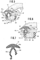
- the present invention proposes a measure which will be described hereinnext with reference to Figs. 5 to 7.
- the window mould 10 of this embodiment comprises an elongate strap portion 10A having a smoothly curved upper surface, and shorter (first) and longer (second) leg portions 10B and 10C which are projected obliquely downward from the generally middle portion of the lower side of the strap portion 10A. It is to be noted that the leg portions 10B and 10C extend entirely along the length of the strap portion 10A. In non- compressed condition of the leg portions 10B and 10C wherein they are applied with no external forces, they assume their free positions as indicated by the phantom lines of Fig. 5. In this free condition, the leg portions 10B and 10C diverge from the strap portion 10A with a sufficient angle defined therebetween.
- the window mould 10 has in its free condition a generally reversed K-shaped cross section.
- the shorter leg portion 10B includes a first section 10B-1 obliquely depending from the strap portion 10A.
- the first section is formed at its leading end with second and third sections 10B-2 and 10B-3 which are projected but slightly in the opposite directions.
- the second section 10B-2 is projected outward, while the third section 10B-3 is projected inward, that is, toward the longer leg portion 10C, so that the first, second and third sections thus united have a generally boot-shaped cross section, as shown in the drawing.
- the longer leg portion 10C includes a first section 10C-1 obliquely depending from the strap portion 10A, a second section 10C-2 extending but slightly from the first section 10C-1 toward the shorter leg portion 10B, a third section 10C-3 extending from the second section 10C-2away from the strap portion 10A, and a fourth section 10C-4 extending but slightly from the third section 10C-3 away from the shorter leg portion 10B, as shown in the drawing.
- the shorter and longer leg portions 10B and 10C are widely opened, so that, upon mounting of the window mould 10 to the parting clearance C, these leg portions 10B and 10C are resiliently engaged with the window pane 12 and the wall portion 20 of the window opening 14, as will be described in detail hereinafter. It is thus to be noted that the shorter and longer leg portions 10B and 10C are each constructed to have a generally "zig-zag" cross section.
- the window mould 10 is brought to the parting clearance C with the shorter and longer leg portions 10B and 10C being pressed toward each other, so that upon mounting of the mould 10 .
- the leg portions 10B and 10C become opened so that the outermost side of the second section 10B-2 of the shorter leg portion 10B is resiliently engaged with or locked to the inboard edge of the window pane 12 and at the same time, the outermost side of the second section 10C-2 (that is the ridge defined between the first and second sections 10C-1 and 10C-2) and the outermost side of the fourth section 10C-4 of the'longer leg portion 10C are resiliently engaged with the wall portion 20 of the window opening 14.
- the outer peripheral edge portion of the assembled window mould 10 is applied with an external force in a direction to pull out the same from the parting clearance C
- the above-mentioned characteristic construction of the longer leg portion 10C increases assuredly the friction force created between the longer leg portion 10C and the wall portion 20 of the window opening 14. This is because, in such a condition, the external force applied to the mould 10 is substantially directly transmitted to the longer leg portion 10C to urge the same against the wall portion 20, strongly.
- the locking engagement of the outwardly projected second section 10B-2 with the inboard edge of the window pane 12 prevents disconnection of the shorter leg portion 10B from the window pane 12.
- an extra adhesive may be applied to the parting clearance C to assure bonding of the leg portions 10B and 10C to the wall portion 20 of the window opening 14 and the window pane 12.
- FIGs. 6 and 7 there is shown a second embodiment of the present invention. Since the second embodiment is similar to the above-mentioned first embodiment of Fig. 5 except the construction of the shorter leg portion, the following explanation will be directed to only the shorter leg portion, and corresponding parts to those of the first embodiment are designated by the same numerals in the drawings.
- the shorter leg portion 10B is so sized that when the shorter and longer leg portions 10B and 10C are brought very close to each other, the third section 10B-3 of the shorter leg portion 10B is put in a recess 30 which is defined by the first and second sections 10C-1 and 10C-2.of the longer leg portion 10C.
- the shorter leg portion 10B of this second embodiment is shorter than that of the first embodiment, as will be seen when comparing Fig. 6 with Fig. 5.
- the advantage provided to the second embodiment is that the window mould 10 thereof is applicable to a parting clearance C which has a very limited space.
- the third section 10B-3 of the shorter leg portion 10B can be compactly put in the recess 30 of the longer leg portion 10C thereby to reduce the substantive distance between the shorter and longer leg portions 10B and 10C in their assembled state.
- the undesired raising phenomenon of the window mould which would occur particularly at the curved section of the parting clearance C, is assuredly prevented because of its characteristic construction practically applied to the leg portions 10B and 10C of the window mould 10.
Landscapes
- Engineering & Computer Science (AREA)
- Mechanical Engineering (AREA)
- Securing Of Glass Panes Or The Like (AREA)
- Window Of Vehicle (AREA)
Applications Claiming Priority (4)
| Application Number | Priority Date | Filing Date | Title |
|---|---|---|---|
| JP208281/82 | 1982-11-27 | ||
| JP57208281A JPS59100014A (ja) | 1982-11-27 | 1982-11-27 | 自動車用ウインドモ−ル |
| JP97463/83 | 1983-05-31 | ||
| JP58097463A JPS59223516A (ja) | 1983-05-31 | 1983-05-31 | 自動車用ウインドモ−ル |
Publications (3)
| Publication Number | Publication Date |
|---|---|
| EP0111106A2 true EP0111106A2 (de) | 1984-06-20 |
| EP0111106A3 EP0111106A3 (en) | 1984-07-18 |
| EP0111106B1 EP0111106B1 (de) | 1988-06-01 |
Family
ID=26438631
Family Applications (1)
| Application Number | Title | Priority Date | Filing Date |
|---|---|---|---|
| EP83110276A Expired EP0111106B1 (de) | 1982-11-27 | 1983-10-14 | Profilleiste für Kraftfahrzeugfenster |
Country Status (5)
| Country | Link |
|---|---|
| US (1) | US4523783A (de) |
| EP (1) | EP0111106B1 (de) |
| AU (1) | AU541184B2 (de) |
| CA (1) | CA1203269A (de) |
| DE (1) | DE3376819D1 (de) |
Cited By (1)
| Publication number | Priority date | Publication date | Assignee | Title |
|---|---|---|---|---|
| GB2205347A (en) * | 1986-12-04 | 1988-12-07 | Tokiwa Chem Ind Ltd | Mounting windscreen |
Families Citing this family (15)
| Publication number | Priority date | Publication date | Assignee | Title |
|---|---|---|---|---|
| DE3320157A1 (de) * | 1983-06-03 | 1984-12-06 | VEGLA Vereinigte Glaswerke GmbH, 5100 Aachen | Glasscheibe, insbesondere autoglasscheibe, mit ueber eine klebeschicht mit ihr verbundenen metallischen halteelementen |
| JPH0624884B2 (ja) * | 1985-12-28 | 1994-04-06 | 日産自動車株式会社 | 自動車用ウインドモ−ルのコ−ナ−モ−ル取付構造 |
| DE8623135U1 (de) * | 1986-08-28 | 1986-11-13 | Adam Opel AG, 6090 Rüsselsheim | Zierleiste |
| US4757659A (en) * | 1986-12-04 | 1988-07-19 | Tokiwa Chemical Industries Co., Ltd. | Front glass mouldings |
| US4833847A (en) * | 1987-03-12 | 1989-05-30 | Toyoda Gosei Co., Ltd. | Flush mounting molding |
| US4905432A (en) * | 1988-03-03 | 1990-03-06 | Navistar International Transportation Corp. | Windshield glass and trim assembly and method for making same |
| GB2219338B (en) * | 1988-06-03 | 1992-04-01 | Tokiwa Chem Ind Ltd | Front glass or windscreen mouldings |
| US4850640A (en) * | 1988-07-18 | 1989-07-25 | Gold Peter N | Auto window moulding |
| EP0379908A3 (de) * | 1989-01-24 | 1992-03-11 | Essex Specialty Products, Inc. | Aufschäumende, heiss schmelzende Masse und ihre Verwendung beim Verkleben einer Windschutzscheibe |
| US5525174A (en) * | 1995-02-22 | 1996-06-11 | Gold; Peter | Auto windshield molding and method of installation |
| US6736144B2 (en) * | 2001-10-23 | 2004-05-18 | Terry Henry James | Felt protector |
| DE102008003252A1 (de) * | 2008-01-04 | 2009-07-16 | Rehau Ag + Co | Scheibenanordnung |
| US9694659B2 (en) | 2013-04-30 | 2017-07-04 | Saint-Gobain Glass France | Sealing arrangement for a fixed vehicle window pane |
| CA2910935C (en) | 2013-06-26 | 2018-03-20 | Saint-Gobain Glass France | Sealing arrangement for a motor vehicle window pane |
| US12560023B2 (en) * | 2022-04-04 | 2026-02-24 | Odl, Incorporated | Apparatus for aligning opposed frame assembly components and centering an insulated glass unit within the frame assembly |
Family Cites Families (9)
| Publication number | Priority date | Publication date | Assignee | Title |
|---|---|---|---|---|
| US2342352A (en) * | 1941-06-23 | 1944-02-22 | Libbey Owens Ford Glass Co | Sash and store front construction |
| GB702743A (en) * | 1950-09-15 | 1954-01-20 | Thomas John Robert Bright | Improvements in draught excluding strips, beadings, mouldings and the like |
| FR1127107A (fr) * | 1955-05-25 | 1956-12-10 | Joint pour assemblage de parois ou panneaux, plus particulièrement de volumes en verre ondulé | |
| DE1279492C2 (de) * | 1963-04-24 | 1973-10-25 | Kraftfahrzeugfenster | |
| US3851432A (en) * | 1973-05-10 | 1974-12-03 | Gen Motors Corp | Motor vehicle window molding |
| JPS5679019A (en) * | 1979-11-28 | 1981-06-29 | Nissan Motor Co Ltd | Window molding for car |
| JPS56157614A (en) * | 1980-05-06 | 1981-12-04 | Nissan Motor Co Ltd | Structure for fixing peripheral molding for window glass |
| JPS5755611A (en) * | 1980-09-22 | 1982-04-02 | Nippon Telegr & Teleph Corp <Ntt> | Josephson ac flip-flop circuit |
| JPS5848549A (ja) * | 1981-09-18 | 1983-03-22 | Fujitsu Ltd | ポ−リング応答制御方式 |
-
1983
- 1983-10-06 US US06/539,551 patent/US4523783A/en not_active Expired - Fee Related
- 1983-10-14 DE DE8383110276T patent/DE3376819D1/de not_active Expired
- 1983-10-14 EP EP83110276A patent/EP0111106B1/de not_active Expired
- 1983-10-18 CA CA000439236A patent/CA1203269A/en not_active Expired
- 1983-11-18 AU AU21497/83A patent/AU541184B2/en not_active Ceased
Cited By (2)
| Publication number | Priority date | Publication date | Assignee | Title |
|---|---|---|---|---|
| GB2205347A (en) * | 1986-12-04 | 1988-12-07 | Tokiwa Chem Ind Ltd | Mounting windscreen |
| GB2205347B (en) * | 1986-12-04 | 1991-06-05 | Tokiwa Chem Ind Ltd | Polymeric mouldings for mounting a windscreen in a vehicle |
Also Published As
| Publication number | Publication date |
|---|---|
| AU541184B2 (en) | 1984-12-20 |
| EP0111106B1 (de) | 1988-06-01 |
| EP0111106A3 (en) | 1984-07-18 |
| DE3376819D1 (en) | 1988-07-07 |
| US4523783A (en) | 1985-06-18 |
| AU2149783A (en) | 1984-05-31 |
| CA1203269A (en) | 1986-04-15 |
Similar Documents
| Publication | Publication Date | Title |
|---|---|---|
| EP0111106B1 (de) | Profilleiste für Kraftfahrzeugfenster | |
| US7565771B2 (en) | Sealing arrangement, especially for sealing window panes of motor vehicle | |
| US6138338A (en) | Method for forming a wind channel seal insert with a belt-line extension | |
| US6240677B1 (en) | Sealing or guiding assemblies and methods of making them | |
| US20090071077A1 (en) | Automotive glass run | |
| EP0876543B1 (de) | Flexible gleitschiene für glassscheiben mit angeformtem versteifungsteil | |
| US4441755A (en) | Window molding for automobile | |
| CN100544985C (zh) | 车辆内部带状压条及使用内部带状压条的密封结构 | |
| US5085006A (en) | Weather strip for motor vehicle | |
| US4621824A (en) | Elongated spacer for arrangement between a mud flap and motor vehicle fender fold | |
| US4974901A (en) | Window molding | |
| JP2555436Y2 (ja) | ウエザーストリップ | |
| US4916873A (en) | Windshield reveal molding with core structure | |
| JP3101212B2 (ja) | 自動車用モールディング | |
| JPH0624883B2 (ja) | 自動車用ウインドウモ−ルデイング | |
| JP3714134B2 (ja) | ガラスランの組付構造 | |
| JP3606111B2 (ja) | ガラスラン取付け構造 | |
| JPH0478496B2 (de) | ||
| JP3145041B2 (ja) | サッシュレスドア型車のセンターピラー構造 | |
| KR0128343Y1 (ko) | 자동차의 도어벨트 스트립 마운트용 죠인트 몰딩의 마운팅 구조 | |
| KR0130017B1 (ko) | 자동차 도어용 하단몰딩의 고정구조 | |
| JP2526581Y2 (ja) | バン型車両における荷箱の上部側枠隅部の化粧構造 | |
| JP3016222B2 (ja) | 自動車ドアの窓下部構造 | |
| JP2564810Y2 (ja) | 自動車用ウエザストリップの取付構造 | |
| JPH022733B2 (de) |
Legal Events
| Date | Code | Title | Description |
|---|---|---|---|
| PUAI | Public reference made under article 153(3) epc to a published international application that has entered the european phase |
Free format text: ORIGINAL CODE: 0009012 |
|
| PUAL | Search report despatched |
Free format text: ORIGINAL CODE: 0009013 |
|
| 17P | Request for examination filed |
Effective date: 19831014 |
|
| AK | Designated contracting states |
Designated state(s): DE FR GB |
|
| AK | Designated contracting states |
Designated state(s): DE FR GB |
|
| RAP1 | Party data changed (applicant data changed or rights of an application transferred) |
Owner name: NISSAN MOTOR CO., LTD. |
|
| GRAA | (expected) grant |
Free format text: ORIGINAL CODE: 0009210 |
|
| AK | Designated contracting states |
Kind code of ref document: B1 Designated state(s): DE FR GB |
|
| REF | Corresponds to: |
Ref document number: 3376819 Country of ref document: DE Date of ref document: 19880707 |
|
| ET | Fr: translation filed | ||
| PLBE | No opposition filed within time limit |
Free format text: ORIGINAL CODE: 0009261 |
|
| STAA | Information on the status of an ep patent application or granted ep patent |
Free format text: STATUS: NO OPPOSITION FILED WITHIN TIME LIMIT |
|
| 26N | No opposition filed | ||
| PGFP | Annual fee paid to national office [announced via postgrant information from national office to epo] |
Ref country code: FR Payment date: 19891005 Year of fee payment: 7 |
|
| PGFP | Annual fee paid to national office [announced via postgrant information from national office to epo] |
Ref country code: DE Payment date: 19891030 Year of fee payment: 7 |
|
| PG25 | Lapsed in a contracting state [announced via postgrant information from national office to epo] |
Ref country code: FR Effective date: 19910628 |
|
| PG25 | Lapsed in a contracting state [announced via postgrant information from national office to epo] |
Ref country code: DE Effective date: 19910702 |
|
| REG | Reference to a national code |
Ref country code: FR Ref legal event code: ST |
|
| PGFP | Annual fee paid to national office [announced via postgrant information from national office to epo] |
Ref country code: GB Payment date: 19911001 Year of fee payment: 9 |
|
| PG25 | Lapsed in a contracting state [announced via postgrant information from national office to epo] |
Ref country code: GB Effective date: 19921014 |
|
| GBPC | Gb: european patent ceased through non-payment of renewal fee |
Effective date: 19921014 |