EP0111171A2 - Filtre à disques rotatifs - Google Patents
Filtre à disques rotatifs Download PDFInfo
- Publication number
- EP0111171A2 EP0111171A2 EP83111237A EP83111237A EP0111171A2 EP 0111171 A2 EP0111171 A2 EP 0111171A2 EP 83111237 A EP83111237 A EP 83111237A EP 83111237 A EP83111237 A EP 83111237A EP 0111171 A2 EP0111171 A2 EP 0111171A2
- Authority
- EP
- European Patent Office
- Prior art keywords
- filter
- shaft
- axial direction
- spring assembly
- elements
- Prior art date
- Legal status (The legal status is an assumption and is not a legal conclusion. Google has not performed a legal analysis and makes no representation as to the accuracy of the status listed.)
- Granted
Links
Images
Classifications
-
- B—PERFORMING OPERATIONS; TRANSPORTING
- B01—PHYSICAL OR CHEMICAL PROCESSES OR APPARATUS IN GENERAL
- B01D—SEPARATION
- B01D33/00—Filters with filtering elements which move during the filtering operation
- B01D33/15—Filters with filtering elements which move during the filtering operation with rotary plane filtering surfaces
- B01D33/21—Filters with filtering elements which move during the filtering operation with rotary plane filtering surfaces with hollow filtering discs transversely mounted on a hollow rotary shaft
- B01D33/23—Construction of discs or component sectors thereof
-
- B—PERFORMING OPERATIONS; TRANSPORTING
- B01—PHYSICAL OR CHEMICAL PROCESSES OR APPARATUS IN GENERAL
- B01D—SEPARATION
- B01D33/00—Filters with filtering elements which move during the filtering operation
- B01D33/80—Accessories
- B01D33/801—Driving means, shaft packing systems or the like
Definitions
- the invention relates to a rotary disk filter, containing a number of filter elements, which are lined up in the form of a filter pack on a common shaft and are clamped together in the axial direction by means of clamping elements with the interposition of sealing elements.
- Filters of this type are subject to considerable temperature fluctuations during operation.
- temperatures can fluctuate between 0 and 100 ° C; G on the e-Bidding chemistry is widely with variations in temperature between -20 and + 200 ° C can be expected.
- These temperature fluctuations cause considerable thermal expansion, with particular problems arising from the presence of materials with different coefficients of thermal expansion.
- the rotary disk filter In known designs, the rotary disk filter must be opened for this purpose in order to gain access to the clamping elements of the filter package. Since in the known designs there are generally several clamping screws distributed over the circumference, there is the additional difficulty, one Apply precisely defined axial clamping force by evenly tightening several clamping elements.
- the invention is therefore based on the object, avoiding these disadvantages of the known designs, to design a rotary disk filter of the type mentioned in such a way that different thermal expansions occurring during operation are largely automatically recorded, i.e. are compensated and that any re-tensioning required is possible in a particularly simple manner.
- the filter package needs to be re-tightened (e.g. to adapt the filter to changing operating conditions or to compensate for any wear that has occurred)
- this can be done in a very simple manner by adjusting a single central clamping screw which engages in the front end of the shaft and via the clamping piece and the disk spring assembly presses on the filter assembly in the axial direction. Due to the direct power transmission, friction losses are largely reduced.
- the central arrangement of the clamping screw also ensures an exact axial alignment of the clamping force.
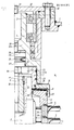
- the drawing shows a vertical partial section of the upper area of a rotary disk filter according to the invention, only the part of the filter that is essential for understanding the invention, namely the tensioning device, being shown.
- a vertical shaft 2 is provided which is driven from below by a motor (not illustrated) and which is supported in two bearings 3, 4 in the upper region of the housing.
- a number of filter elements 5 are lined up on the shaft 2, only the two top filter elements 5 being shown in the drawing. These filter elements 5 can be designed in detail as described in the applicant's German patent application P 32 32 354.9.
- a central clamping screw 6, a clamping piece 7, a plate spring pack 8 and a pressure piece 9 are provided.
- the central clamping screw 6 engages in a threaded bushing 10, which is fastened by means of a locking pin 11 in a blind hole at the front end of the shaft 2.
- the threaded bush 10 forms a wearing part that can be replaced in a simple manner by loosening the locking pin 11 without having to remove the shaft 2 with the filter package.
- the central clamping screw 6 lies with its head 6a in a recess 12 of the clamping piece 7 which is large enough to be able to tighten or loosen the clamping screw 6 with a key placed on the head 6a.
- the clamping piece 7 surrounds the end 2a of the shaft 2 in a bush-like manner and is slidably_guided on this shaft end 2a in the axial direction.
- the lower edge of the clamping piece 7 lies on the plate spring assembly 8, which is formed by a number of ring plate springs surrounding the shaft 2.
- This disc spring assembly 8 is supported on its underside on the pressure piece 9, which in turn rests on the hub 13 of the uppermost filter element 5.
- the plate spring assembly 8 is sealed off from the interior 14 of the rotary disk filter by a sealing ring 15, which is in sealing contact with the clamping piece 7 and the annular pressure piece 9 via sealing elements 16 and 17.
- Another sealing element 18 is provided between the inner circumference of the annular pressure piece 9 and the shaft end 2a.
- a sealing element 19 is provided between the pressure piece 9 and the uppermost filter element 5. Sealing elements 20 are present between the individual filter elements 5.
- the clamping piece 7 can be moved axially to a limited extent and is guided via sealing elements 21, 22 in a shoulder 23a of a bearing bush 23, which carries the inner ring of the bearings 3, 4.
- This bearing bushing 23 rotating with the shaft 2 also contains, in a recess 24 located above the tensioning screw 6, a further plate spring assembly 25 which is arranged between two pressure plates 26, 27.
- the outer (upper) pressure plate 26 abuts a central threaded pin 28 which is screwed into a threaded through bore of the bearing bush 23.
- the inner (lower) pressure plate 27 abuts the head 6a of the central clamping screw 6.
- a locking ring 29 secures the pressure plate 27 against falling out from the bush 23 when pulling the upper bearing structure from the shaft.
- the shaft 2 carrying the filter package is supported on the bearing bush 23 via the clamping screw 6, the pressure plate 27, the plate spring package 25, the pressure plate 26 and the threaded pin 28.
- the tension of the plate spring assembly 25 and thus the axial preload of the shaft 2 can be set in the desired manner.
- the threaded pin 28 is easily accessible after loosening the threaded pin 31 provided in the cover 30.
- the last-mentioned setting of the preload of the plate spring assembly 25 can thus change the axial preload of the shaft 2 (such a preload pushing the shaft down is necessary, in particular, to counteract a buoyancy movement when cleaning the filter elements by rotation).
- the cover 30 is removed after loosening the screws 32. Then the camp bush 23 including the bearing 3, 4 and the T ellerfederwees be deducted 25 upward, whereby the head 6a of the central clamping screw 6 is freely accessible.
- the setting of the preload of the plate spring assembly 8 can be carried out independently of the setting of the preload of the plate spring assembly 25.
Landscapes
- Chemical & Material Sciences (AREA)
- Chemical Kinetics & Catalysis (AREA)
- Ultra Sonic Daignosis Equipment (AREA)
- Automatic Disk Changers (AREA)
- Facsimile Scanning Arrangements (AREA)
- Lubrication Details And Ventilation Of Internal Combustion Engines (AREA)
- Sealing Of Jars (AREA)
- Filtering Of Dispersed Particles In Gases (AREA)
Priority Applications (1)
| Application Number | Priority Date | Filing Date | Title |
|---|---|---|---|
| AT83111237T ATE25590T1 (de) | 1982-11-10 | 1983-11-10 | Rotationsscheibenfilter. |
Applications Claiming Priority (2)
| Application Number | Priority Date | Filing Date | Title |
|---|---|---|---|
| DE19823241617 DE3241617A1 (de) | 1982-11-10 | 1982-11-10 | Rotationsscheibenfilter |
| DE3241617 | 1982-11-10 |
Publications (3)
| Publication Number | Publication Date |
|---|---|
| EP0111171A2 true EP0111171A2 (fr) | 1984-06-20 |
| EP0111171A3 EP0111171A3 (en) | 1985-10-02 |
| EP0111171B1 EP0111171B1 (fr) | 1987-03-04 |
Family
ID=6177799
Family Applications (1)
| Application Number | Title | Priority Date | Filing Date |
|---|---|---|---|
| EP83111237A Expired EP0111171B1 (fr) | 1982-11-10 | 1983-11-10 | Filtre à disques rotatifs |
Country Status (3)
| Country | Link |
|---|---|
| EP (1) | EP0111171B1 (fr) |
| AT (1) | ATE25590T1 (fr) |
| DE (2) | DE3241617A1 (fr) |
Cited By (2)
| Publication number | Priority date | Publication date | Assignee | Title |
|---|---|---|---|---|
| DE102004028036A1 (de) * | 2004-06-09 | 2006-01-05 | Airbus Deutschland Gmbh | Wasseraufbereitung für Luftfahrzeuge |
| CN109045796A (zh) * | 2018-09-27 | 2018-12-21 | 江苏巨能机械有限公司 | 改进的过滤板面网拉紧工装 |
Family Cites Families (7)
| Publication number | Priority date | Publication date | Assignee | Title |
|---|---|---|---|---|
| FR1568111A (fr) * | 1968-02-07 | 1969-05-23 | ||
| US3608731A (en) * | 1970-01-16 | 1971-09-28 | Ametek Inc | Centrifugal discharge filter seals |
| US3693803A (en) * | 1970-11-23 | 1972-09-26 | Hans Muller Chemie Apparatebau | Filter device |
| NL7400613A (nl) * | 1974-01-17 | 1975-07-21 | Stamicarbon | Werkwijze en inrichting voor het filtreren van media. |
| US3950254A (en) * | 1974-05-13 | 1976-04-13 | Artisan Industries Inc. | Solids concentrator with a rotor having ploughs thereon |
| DE2845108A1 (de) * | 1978-10-17 | 1980-04-30 | Schenk Filterbau Gmbh | Fluessigkeitsfilter |
| DE3100781A1 (de) * | 1981-01-13 | 1982-08-05 | Seitz-Werke Gmbh, 6550 Bad Kreuznach | "anpressvorrichtung fuer die gestapelten filterelemente eines fluessigkeitsfilters" |
-
1982
- 1982-11-10 DE DE19823241617 patent/DE3241617A1/de not_active Withdrawn
-
1983
- 1983-11-10 AT AT83111237T patent/ATE25590T1/de not_active IP Right Cessation
- 1983-11-10 DE DE8383111237T patent/DE3369908D1/de not_active Expired
- 1983-11-10 EP EP83111237A patent/EP0111171B1/fr not_active Expired
Cited By (3)
| Publication number | Priority date | Publication date | Assignee | Title |
|---|---|---|---|---|
| DE102004028036A1 (de) * | 2004-06-09 | 2006-01-05 | Airbus Deutschland Gmbh | Wasseraufbereitung für Luftfahrzeuge |
| US7648628B2 (en) | 2004-06-09 | 2010-01-19 | Airbus Deutschland Gmbh | Water treatment for an aircraft |
| CN109045796A (zh) * | 2018-09-27 | 2018-12-21 | 江苏巨能机械有限公司 | 改进的过滤板面网拉紧工装 |
Also Published As
| Publication number | Publication date |
|---|---|
| ATE25590T1 (de) | 1987-03-15 |
| DE3369908D1 (en) | 1987-04-09 |
| EP0111171B1 (fr) | 1987-03-04 |
| DE3241617A1 (de) | 1984-05-10 |
| EP0111171A3 (en) | 1985-10-02 |
Similar Documents
| Publication | Publication Date | Title |
|---|---|---|
| DE3017855A1 (de) | Kupplungsmechanismus mit federplatte | |
| DE4322506A1 (de) | Kupplungsabdeckungsausbildung | |
| EP0239830A2 (fr) | Dispositif de réglage de la position angulaire relative entre une roue dentée et une couronne dentée coaxiale | |
| DD222794A5 (de) | Anordnung zum befestigen eines walzenrings auf einer fliegend gelagerten walzenwelle | |
| DE3151486C1 (de) | Einstellbare Reibungsschlupfkupplung | |
| EP2193850B1 (fr) | Broyeur de charbon | |
| DE1943336B2 (de) | Reibungskupplung | |
| DE4332602C2 (de) | Druckmaschine mit Druckwalze und Druckkopf | |
| DE69000748T2 (de) | Kreismesseranordnung. | |
| EP0111171A2 (fr) | Filtre à disques rotatifs | |
| EP0131106B1 (fr) | Dispositif d'encrage pour une machine d'impression | |
| DE10105670B4 (de) | Einstellvorrichtung für einen Druckring und einen Stahlring eines übertragungsmechanismus in einer Rundstrickmaschine | |
| DE4442594B4 (de) | Reibungskupplung | |
| DE4412106A1 (de) | Reibungskupplung mit flacher Federkennlinie | |
| EP1047491A1 (fr) | Boitier pour micromelangeurs | |
| DE10049652B4 (de) | Druckplattenbaugruppe | |
| DE202004004181U1 (de) | Spannzylinder mit Verschlußkappe | |
| DE2544386B2 (de) | Haltevorrichtung für die Mahlscheiben von Scheibenrefinern | |
| EP0403676A1 (fr) | Joint mécanique | |
| DE3544358A1 (de) | Vorrichtung zum einspannen von stanzblechen | |
| DE2637217A1 (de) | Absperrschieber mit zweiteiliger schieberzunge | |
| DE3029767C2 (de) | Pressenkopf für Teigwarenpresse | |
| DE3123284C2 (de) | Rutschkupplung | |
| DE2705139B2 (de) | Druckminderer | |
| DE2904883B1 (de) | Druckkolben fuer Druckgiessmaschinen |
Legal Events
| Date | Code | Title | Description |
|---|---|---|---|
| PUAI | Public reference made under article 153(3) epc to a published international application that has entered the european phase |
Free format text: ORIGINAL CODE: 0009012 |
|
| AK | Designated contracting states |
Designated state(s): AT CH DE FR GB IT LI NL |
|
| PUAL | Search report despatched |
Free format text: ORIGINAL CODE: 0009013 |
|
| AK | Designated contracting states |
Designated state(s): AT CH DE FR GB IT LI NL |
|
| 17P | Request for examination filed |
Effective date: 19850831 |
|
| 17Q | First examination report despatched |
Effective date: 19860526 |
|
| GRAA | (expected) grant |
Free format text: ORIGINAL CODE: 0009210 |
|
| AK | Designated contracting states |
Kind code of ref document: B1 Designated state(s): AT CH DE FR GB IT LI NL |
|
| REF | Corresponds to: |
Ref document number: 25590 Country of ref document: AT Date of ref document: 19870315 Kind code of ref document: T |
|
| ITF | It: translation for a ep patent filed | ||
| REF | Corresponds to: |
Ref document number: 3369908 Country of ref document: DE Date of ref document: 19870409 |
|
| ET | Fr: translation filed | ||
| PLBE | No opposition filed within time limit |
Free format text: ORIGINAL CODE: 0009261 |
|
| STAA | Information on the status of an ep patent application or granted ep patent |
Free format text: STATUS: NO OPPOSITION FILED WITHIN TIME LIMIT |
|
| 26N | No opposition filed | ||
| ITTA | It: last paid annual fee | ||
| PGFP | Annual fee paid to national office [announced via postgrant information from national office to epo] |
Ref country code: FR Payment date: 19951009 Year of fee payment: 13 |
|
| PGFP | Annual fee paid to national office [announced via postgrant information from national office to epo] |
Ref country code: AT Payment date: 19951012 Year of fee payment: 13 |
|
| PGFP | Annual fee paid to national office [announced via postgrant information from national office to epo] |
Ref country code: GB Payment date: 19951017 Year of fee payment: 13 |
|
| PGFP | Annual fee paid to national office [announced via postgrant information from national office to epo] |
Ref country code: NL Payment date: 19951019 Year of fee payment: 13 |
|
| PG25 | Lapsed in a contracting state [announced via postgrant information from national office to epo] |
Ref country code: GB Effective date: 19961110 Ref country code: AT Effective date: 19961110 |
|
| PG25 | Lapsed in a contracting state [announced via postgrant information from national office to epo] |
Ref country code: NL Effective date: 19970601 |
|
| GBPC | Gb: european patent ceased through non-payment of renewal fee |
Effective date: 19961110 |
|
| PG25 | Lapsed in a contracting state [announced via postgrant information from national office to epo] |
Ref country code: FR Effective date: 19970731 |
|
| NLV4 | Nl: lapsed or anulled due to non-payment of the annual fee |
Effective date: 19970601 |
|
| REG | Reference to a national code |
Ref country code: FR Ref legal event code: ST |
|
| PGFP | Annual fee paid to national office [announced via postgrant information from national office to epo] |
Ref country code: CH Payment date: 20011022 Year of fee payment: 19 |
|
| PGFP | Annual fee paid to national office [announced via postgrant information from national office to epo] |
Ref country code: DE Payment date: 20011228 Year of fee payment: 19 |
|
| PG25 | Lapsed in a contracting state [announced via postgrant information from national office to epo] |
Ref country code: LI Free format text: LAPSE BECAUSE OF NON-PAYMENT OF DUE FEES Effective date: 20021130 Ref country code: CH Free format text: LAPSE BECAUSE OF NON-PAYMENT OF DUE FEES Effective date: 20021130 |
|
| PG25 | Lapsed in a contracting state [announced via postgrant information from national office to epo] |
Ref country code: DE Free format text: LAPSE BECAUSE OF NON-PAYMENT OF DUE FEES Effective date: 20030603 |
|
| REG | Reference to a national code |
Ref country code: CH Ref legal event code: PL |