EP0111176A1 - Procédé et dispositif pour produire des particules de fer réduit et de fer liquide à partir de particules de minerais de fer - Google Patents
Procédé et dispositif pour produire des particules de fer réduit et de fer liquide à partir de particules de minerais de fer Download PDFInfo
- Publication number
- EP0111176A1 EP0111176A1 EP83111296A EP83111296A EP0111176A1 EP 0111176 A1 EP0111176 A1 EP 0111176A1 EP 83111296 A EP83111296 A EP 83111296A EP 83111296 A EP83111296 A EP 83111296A EP 0111176 A1 EP0111176 A1 EP 0111176A1
- Authority
- EP
- European Patent Office
- Prior art keywords
- gas
- particles
- melter gasifier
- iron
- grain fraction
- Prior art date
- Legal status (The legal status is an assumption and is not a legal conclusion. Google has not performed a legal analysis and makes no representation as to the accuracy of the status listed.)
- Granted
Links
- XEEYBQQBJWHFJM-UHFFFAOYSA-N Iron Chemical compound [Fe] XEEYBQQBJWHFJM-UHFFFAOYSA-N 0.000 title claims abstract description 213
- 229910052742 iron Inorganic materials 0.000 title claims abstract description 106
- 238000000034 method Methods 0.000 title claims abstract description 51
- 239000007788 liquid Substances 0.000 title claims abstract description 10
- 238000004519 manufacturing process Methods 0.000 title claims abstract description 4
- 239000008188 pellet Substances 0.000 title description 3
- UQSXHKLRYXJYBZ-UHFFFAOYSA-N Iron oxide Chemical compound [Fe]=O UQSXHKLRYXJYBZ-UHFFFAOYSA-N 0.000 title 2
- 239000002245 particle Substances 0.000 claims abstract description 85
- 238000002844 melting Methods 0.000 claims abstract description 16
- 230000008018 melting Effects 0.000 claims abstract description 16
- 239000007789 gas Substances 0.000 claims description 171
- 238000001816 cooling Methods 0.000 claims description 40
- 239000003245 coal Substances 0.000 claims description 32
- NINIDFKCEFEMDL-UHFFFAOYSA-N Sulfur Chemical compound [S] NINIDFKCEFEMDL-UHFFFAOYSA-N 0.000 claims description 26
- 229910052717 sulfur Inorganic materials 0.000 claims description 26
- 239000011593 sulfur Substances 0.000 claims description 26
- 239000000112 cooling gas Substances 0.000 claims description 15
- 239000003795 chemical substances by application Substances 0.000 claims description 12
- 229910000805 Pig iron Inorganic materials 0.000 claims description 10
- QVGXLLKOCUKJST-UHFFFAOYSA-N atomic oxygen Chemical compound [O] QVGXLLKOCUKJST-UHFFFAOYSA-N 0.000 claims description 10
- 229910052760 oxygen Inorganic materials 0.000 claims description 10
- 239000001301 oxygen Substances 0.000 claims description 10
- 239000002893 slag Substances 0.000 claims description 9
- 239000007787 solid Substances 0.000 claims description 7
- 238000000926 separation method Methods 0.000 claims description 6
- 230000003009 desulfurizing effect Effects 0.000 claims description 5
- 238000002309 gasification Methods 0.000 claims description 5
- 238000007664 blowing Methods 0.000 claims description 4
- 239000010419 fine particle Substances 0.000 claims description 3
- 239000013590 bulk material Substances 0.000 claims description 2
- 239000011362 coarse particle Substances 0.000 claims description 2
- 239000012615 aggregate Substances 0.000 claims 2
- 238000002347 injection Methods 0.000 claims 2
- 239000007924 injection Substances 0.000 claims 2
- 238000009434 installation Methods 0.000 claims 2
- 238000011946 reduction process Methods 0.000 claims 1
- 238000005406 washing Methods 0.000 claims 1
- 230000001914 calming effect Effects 0.000 description 9
- 238000010521 absorption reaction Methods 0.000 description 7
- 238000006477 desulfuration reaction Methods 0.000 description 7
- 230000023556 desulfurization Effects 0.000 description 7
- 239000000463 material Substances 0.000 description 7
- CURLTUGMZLYLDI-UHFFFAOYSA-N Carbon dioxide Chemical compound O=C=O CURLTUGMZLYLDI-UHFFFAOYSA-N 0.000 description 4
- 238000010438 heat treatment Methods 0.000 description 4
- 239000002826 coolant Substances 0.000 description 3
- 230000000630 rising effect Effects 0.000 description 3
- 241001311578 Calyptraea chinensis Species 0.000 description 2
- OKTJSMMVPCPJKN-UHFFFAOYSA-N Carbon Chemical compound [C] OKTJSMMVPCPJKN-UHFFFAOYSA-N 0.000 description 2
- 229910052799 carbon Inorganic materials 0.000 description 2
- 239000001569 carbon dioxide Substances 0.000 description 2
- 229910002092 carbon dioxide Inorganic materials 0.000 description 2
- 239000012159 carrier gas Substances 0.000 description 2
- 230000004927 fusion Effects 0.000 description 2
- 230000036284 oxygen consumption Effects 0.000 description 2
- 238000005245 sintering Methods 0.000 description 2
- 230000008646 thermal stress Effects 0.000 description 2
- XLYOFNOQVPJJNP-UHFFFAOYSA-N water Substances O XLYOFNOQVPJJNP-UHFFFAOYSA-N 0.000 description 2
- 229910000831 Steel Inorganic materials 0.000 description 1
- 206010053615 Thermal burn Diseases 0.000 description 1
- 230000015572 biosynthetic process Effects 0.000 description 1
- AXCZMVOFGPJBDE-UHFFFAOYSA-L calcium dihydroxide Chemical compound [OH-].[OH-].[Ca+2] AXCZMVOFGPJBDE-UHFFFAOYSA-L 0.000 description 1
- 239000000920 calcium hydroxide Substances 0.000 description 1
- 229910001861 calcium hydroxide Inorganic materials 0.000 description 1
- 235000011116 calcium hydroxide Nutrition 0.000 description 1
- 238000006243 chemical reaction Methods 0.000 description 1
- 238000002485 combustion reaction Methods 0.000 description 1
- 238000004891 communication Methods 0.000 description 1
- 239000000110 cooling liquid Substances 0.000 description 1
- 230000008878 coupling Effects 0.000 description 1
- 238000010168 coupling process Methods 0.000 description 1
- 238000005859 coupling reaction Methods 0.000 description 1
- 230000000593 degrading effect Effects 0.000 description 1
- 230000006866 deterioration Effects 0.000 description 1
- 239000000428 dust Substances 0.000 description 1
- 238000010891 electric arc Methods 0.000 description 1
- 239000012530 fluid Substances 0.000 description 1
- 238000007654 immersion Methods 0.000 description 1
- 239000000155 melt Substances 0.000 description 1
- 239000002184 metal Substances 0.000 description 1
- 229910052751 metal Inorganic materials 0.000 description 1
- 239000000203 mixture Substances 0.000 description 1
- 238000013021 overheating Methods 0.000 description 1
- JTJMJGYZQZDUJJ-UHFFFAOYSA-N phencyclidine Chemical group C1CCCCN1C1(C=2C=CC=CC=2)CCCCC1 JTJMJGYZQZDUJJ-UHFFFAOYSA-N 0.000 description 1
- 238000010405 reoxidation reaction Methods 0.000 description 1
- 230000000717 retained effect Effects 0.000 description 1
- 238000010079 rubber tapping Methods 0.000 description 1
- 238000007873 sieving Methods 0.000 description 1
- 239000010959 steel Substances 0.000 description 1
- 238000011144 upstream manufacturing Methods 0.000 description 1
Images


Classifications
-
- C—CHEMISTRY; METALLURGY
- C21—METALLURGY OF IRON
- C21B—MANUFACTURE OF IRON OR STEEL
- C21B13/00—Making spongy iron or liquid steel, by direct processes
- C21B13/14—Multi-stage processes processes carried out in different vessels or furnaces
-
- C—CHEMISTRY; METALLURGY
- C21—METALLURGY OF IRON
- C21B—MANUFACTURE OF IRON OR STEEL
- C21B13/00—Making spongy iron or liquid steel, by direct processes
- C21B13/0006—Making spongy iron or liquid steel, by direct processes obtaining iron or steel in a molten state
- C21B13/0013—Making spongy iron or liquid steel, by direct processes obtaining iron or steel in a molten state introduction of iron oxide into a bath of molten iron containing a carbon reductant
- C21B13/002—Reduction of iron ores by passing through a heated column of carbon
-
- C—CHEMISTRY; METALLURGY
- C21—METALLURGY OF IRON
- C21B—MANUFACTURE OF IRON OR STEEL
- C21B2100/00—Handling of exhaust gases produced during the manufacture of iron or steel
- C21B2100/20—Increasing the gas reduction potential of recycled exhaust gases
- C21B2100/28—Increasing the gas reduction potential of recycled exhaust gases by separation
- C21B2100/282—Increasing the gas reduction potential of recycled exhaust gases by separation of carbon dioxide
-
- C—CHEMISTRY; METALLURGY
- C21—METALLURGY OF IRON
- C21B—MANUFACTURE OF IRON OR STEEL
- C21B2100/00—Handling of exhaust gases produced during the manufacture of iron or steel
- C21B2100/40—Gas purification of exhaust gases to be recirculated or used in other metallurgical processes
- C21B2100/42—Sulphur removal
-
- C—CHEMISTRY; METALLURGY
- C21—METALLURGY OF IRON
- C21B—MANUFACTURE OF IRON OR STEEL
- C21B2100/00—Handling of exhaust gases produced during the manufacture of iron or steel
- C21B2100/40—Gas purification of exhaust gases to be recirculated or used in other metallurgical processes
- C21B2100/44—Removing particles, e.g. by scrubbing, dedusting
-
- Y—GENERAL TAGGING OF NEW TECHNOLOGICAL DEVELOPMENTS; GENERAL TAGGING OF CROSS-SECTIONAL TECHNOLOGIES SPANNING OVER SEVERAL SECTIONS OF THE IPC; TECHNICAL SUBJECTS COVERED BY FORMER USPC CROSS-REFERENCE ART COLLECTIONS [XRACs] AND DIGESTS
- Y02—TECHNOLOGIES OR APPLICATIONS FOR MITIGATION OR ADAPTATION AGAINST CLIMATE CHANGE
- Y02P—CLIMATE CHANGE MITIGATION TECHNOLOGIES IN THE PRODUCTION OR PROCESSING OF GOODS
- Y02P10/00—Technologies related to metal processing
- Y02P10/10—Reduction of greenhouse gas [GHG] emissions
- Y02P10/122—Reduction of greenhouse gas [GHG] emissions by capturing or storing CO2
Definitions
- the invention relates to a method according to the preamble of claim 1. Furthermore, it relates to a system according to the preamble of claims 25, 32 and 33.
- lumpy iron ore is to be understood to mean iron ore in any lumpy form, ie also in the form of pellets .
- a method and a plant of this type are known from DE-C2-30 34 539.
- the known method about 40% more reducing gas is produced when the sponge iron melts than is required to produce the same amount of sponge iron.
- each coupling of several systems leads to a reduction in the availability of the overall system and thus to a deterioration in economy.
- Small iron sponge particles stay longer in the fluidized bed, warm up to a higher temperature and are melted faster.
- the method according to the invention is characterized by the features of claim 1. Advantageous embodiments of this method can be found in claims 2 to 24.
- the system according to the invention is characterized by the features of claim 25.
- Advantageous embodiments of the device according to the invention are described in claims 26 to 36.
- the entire amount of the sponge iron particles produced in the direct reduction unit is not supplied to the melter gasifier, but only a part, so that less gas is produced when this partial amount is melted, and an excess of reducing gas can be avoided in this way.
- the partial quantity of sponge iron particles supplied to the melter gasifier is selected insofar as the upper limit of the particle size is limited. This avoids that larger pieces of iron sponge migrate through the coal fluidized bed without sufficient heating and then there is a build-up of material which can only be melted with increased energy expenditure in the melting zone of the melter gasifier.
- the coarse-grain fraction separated on the way from the reduction unit to the melter gasifier can either be fed to another meltdown vessel, such as an electric arc furnace, when hot, but it can also be hot-briquetted, passivated or cooled in order to be used as a feedstock for one Melting furnace to be available.
- another meltdown vessel such as an electric arc furnace
- the coarse grain separator must be designed for temperatures between 700 ° and 900 ° C, since the iron sponge particles leave the direct reduction unit at these temperatures. With some classifiers, especially when using screens, this can cause difficulties.
- the separated sponge iron particles are preferably cooled by cooled, cleaned and treated top gas from the reduction unit, which, after the heat exchange with the sponge iron particles, is passed to the reduction unit from the melter gasifier hot reducing gas stream is added for temperature control. In this way, the top gas of the reduction unit is also used economically.
- the separation of the sponge iron particles of the coarse grain fraction increases the relative proportion of fine material of the sponge iron fed to the melter and thus also the amount of possible discharge of fine material from the melter.
- the point at which the sponge iron particles are released within the melter gasifier is therefore moved down from the lid of the vessel to the vicinity of the upper limit of the coal fluidized bed. This is preferably done through a downpipe which dips from above into the interior of the melter gasifier up to the vicinity of the upper limit of the coal fluidized bed formed in the melter gasifier.
- the plant for the direct production of molten pig iron from lumpy iron ore shown schematically in FIG. 1, contains a melter gasifier 1 of the type described in EP-B1-0 010 627. Above the melter gasifier, a shaft furnace 2 is arranged, which according to its mode of operation is connected to the upper one Part of a blast furnace or a direct reduction shaft furnace can be compared. The latter is described in principle, for example, in DE-A-29 35 707.
- Pieces of iron ore are fed to the direct reduction shaft furnace from above - indicated by an arrow 3 - in the form a loose bed in the shaft furnace sinks and is reduced to sponge iron by means of a hot reducing gas blown in via a central gas inlet 4 at a temperature of about 750 ° to 900 ° C.
- the used reducing gas hereinafter called blast furnace gas, leaves the shaft furnace 2 via an upper gas outlet 5.
- the hot sponge iron produced by reducing the lumpy iron ore is removed from the direct reduction shaft furnace 2 at a temperature of approximately 750 ° to 850 ° C. discharged and passes through a pipe 6 into a coarse grain separator 7.
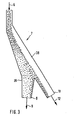
- a coarse grain separator 7 This is, as described in more detail with reference to FIG. 3, formed.
- it contains a thermally resilient sieve with a mesh size of, for example, 12 mm, through which iron sponge particles with a size of more than 12 mm are retained.
- the sponge iron particles of the fine grain fraction leave the coarse grain separator 7 via a first outlet opening 8 and pass through a pipe 9 into a discharge device 10 which contains, for example, a scraper or a screw.
- the iron sponge particles of the coarse grain fraction leave the coarse grain separator 7 through a second outlet opening 11 and reach a cooling unit 13 via a pipe 12, in which they are cooled down to room temperature so that they can be transported to the place where they are processed without a great risk of reoxidation should be.
- the exit of the cooled sponge iron particles from the cooling unit 13 is denoted by 14.
- the discharge device 10 has an outlet opening 16 for the iron sponge particles at the lower end; which at least one down pipe 17 is connected to the interior of the melter gasifier 1.
- the sponge iron particles are dispensed in a metered manner via the outlet opening 16.
- the feed materials required for the melter gasifier are added continuously or intermittently in the amount required for the melter process via the downpipe 17.
- the amount of coal required to form and maintain the coal fluidized bed is added directly to the melter gasifier via a pipe 15.
- the melter gas can be divided into three sections in the operating state, namely a lower section 18, in which pig iron and slag are located, a middle section 19 for the coal fluidized bed and an expanded section upper section 20, which serves as a calming room.
- the sponge iron particles are not supplied at the upper limit of the calming space, but within the calming space near the upper limit of the coal fluidized bed 19. In the present case, this is done by immersing the downpipe 17 deeply into the calming space 20.
- the amount of fine grain discharged with the gas from the melter gasifier which plays a special role in the process according to the invention in relation to the total amount of sponge iron brought into the melter gasifier, can be greatly reduced.
- the cheapest immersion depth of the downpipe 17 can be easily determined experimentally.
- the downpipe expediently ends just above the upper limit of the coal fluidized bed.
- one or more downpipes 17 also makes it possible, by deflecting these pipes at the lower end, by attaching baffle plates, to substantially reduce the vertical speed component of the falling material and thus to increase the residence time of the sponge iron particles in the carbon fluid bed. Because of the high thermal stress of a down pipe immersed in the interior of the melter gasifier, it is advisable to cool the pipe. One way of forming such a down pipe is described with reference to FIG. 2.
- the channels 21 and 222 for tapping the pig iron and the slag are still in the melter gasifier 1 and a nozzle 23 for blowing in an oxygen-containing gas are indicated schematically.
- the reducing gas generated in the melter gasifier 1 leaves the melter gasifier via the outlet 24 at a temperature of approximately 1200 ° C. From here it is forwarded via the reducing gas line 25 to the gas inlet 4 of the direct reduction unit 2. Since the reducing gas introduced into the direct reduction unit 2 must not exceed a temperature of 900 ° C., the hot reducing gas stream rising in the line 25 is added to the cooling gas at the point 26 for cooling control, which is supplied via the line 27. This cooling gas is recirculated blast furnace gas from the direct reduction unit 2 after it has been washed and cooled in a blast furnace gas scrubber 28 and the CO 2 content has been reduced in a CO 2 absorption tower 29.
- the blast furnace gas prepared in this way could already be mixed with the hot reducing gas from the melter gasifier for temperature control, in the exemplary embodiment described it was passed over the cooler 13 and, in the direct heat exchange with the iron sponge particles of the coarse grain fraction, causes these iron sponge particles to cool down.
- the processed top gas heats up to approx. 500 ° C. It is then mixed via line 27 at point 26 into the hot reducing gas stream of line 25 in order to lower its temperature to a value below 900 ° C. If more iron sponge than pig iron is to be produced in the system, it is necessary to preheat a portion of the processed blast furnace gas in the separate recuperator 31 in parallel with the cooling unit 13 in order to be able to set the desired bus gas temperature.
- the unprocessed top gas behind the top gas scrubber 28, the amount of which depends on the heat requirement, is to be used as the heating gas. This also prevents the circulation gas from being enriched with inactive components such as N 2 .
- 30 denotes a compressor upstream of the CO 2 absorption tower 29, which generates the required pressure.
- it is necessary to desulfurize the gas from the melter gasifier 1 in the hot gas desulfurization unit 32.
- some cold gas can be added to this gas to adjust its temperature to the desulfurization process.
- Fig. 2 the part of a down pipe 17 immersed in the melter gasifier is shown in section. Because of the high thermal stress inside the melter gasifier, the downpipe is provided with liquid cooling.
- a liquid channel is formed by three metal tubes 31, 32 and 33 arranged concentrically to one another, through which a cooling liquid, for example water, is passed.
- the cooling system is covered on all sides with a refractory layer 34.
- the downpipe 17 shown contains measures by deflection to reduce the vertical speed of the falling sponge iron particles and thus to increase the dwell time here because of the reduced entry speed into the coal fluidized bed.
- projections 35 arranged in a cascade are provided, on which material can deposit, which thereby serves as wear protection.
- a baffle plate 36 preferably in the form of a blunt cone similar to a Chinese hat, can also be provided at the lower outlet opening of the tube.
- the falling sponge iron particles are deflected and braked in a meandering manner by the projections 35 in the tube and deflected approximately in a horizontal direction by the baffle plate 36, as a result of which their vertical speed component is considerably reduced.
- the ceiling of the melter gasifier is designated by 37 in FIG.
- the coarse grain separator 7 shown schematically in FIG. 3 is designed in the form of an inclined chute 38 with at least one connecting piece 39 branching off from it.
- the tube through which the sponge iron particles discharged from the direct reduction shaft furnace are fed is designated by 6
- the first outlet opening for the fine-grain fraction is 8
- the second outlet opening for the coarse-grain fraction is 11.
- the bulk material entering the coarse grain separator 7 from above is naturally separated during the movement by the coarse grain separator, ie the fine particles settle down and the coarse particles collect on the top.
- the flow profile shown schematically in FIG. 3 is obtained, ie the coarse sponge iron particles are essentially forwarded via the downpipe 38 to the second outlet opening 12 and removed from there.
- the removal of the fine iron sponge particles is controlled according to FIG. 1 by a discharge device 10, which is connected to the G robkornabscheider 7 is connected, then, as desired, the flow resistance for gas rising from the melter gas can be kept relatively high.
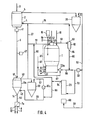
- a direct reduction unit designed as a direct reduction shaft furnace 2 has at the top an inlet device 3 for the lumpy iron ore and a gas outlet 5 for the used reducing gas (blast furnace gas) and fuses, a controllable discharge device 41 for the direct reduction of iron sponge particles obtained from the iron ore and a gas inlet 4 for hot reducing.
- the melter gasifier 1 essentially corresponds to the melter gasifier of the first embodiment.
- the ceiling of the upper section 20 serving as a calming space here has a chamber called a carburetor head 42, which is in communication with the calming space.
- a gas outlet 43 for the reducing gas (raw gas) generated in the melter gasifier is provided in the gasifier head.
- a gas inlet 44 for washed and processed top gas from the direct reduction shaft furnace is provided in the gasifier head.
- an inlet 45 for a desulfurizing agent is provided in the gasifier head.
- outlets 21 for molten pig iron and 22 for molten slag In the lower area of the melting gasifier there are outlets 21 for molten pig iron and 22 for molten slag, furthermore at least one nozzle 23 or at least one burner 23a for blowing in above the slag level of gases and fine-grained solids.
- the cooling unit 13a for the hot sponge iron particles discharged by the discharge device 41 there is a cooling unit 13a for the hot sponge iron particles discharged by the discharge device 41.
- the inlet opening 46 of the cooling unit 13a for the hot sponge iron particles is connected to the discharge device 41 through the downpipe 6.
- the down pipe 6 is assigned a level measuring device 47, by means of which the discharge device 41 can be controlled.
- the cooling unit 13a has an outlet 48 for the cooling gas in the upper region next to the inlet opening 46 for the hot sponge iron particles and an inlet 49 for the cooling gas in the lower region next to an outlet opening 14 for the cooled sponge iron particles.
- cooling takes place in countercurrent and in direct exchange with the iron sponge particles sinking in the cooling unit. Since not only the coarse-grain fraction of the sponge iron particles is fed to the cooling unit 13a, as in the exemplary embodiment according to FIG. 1, it is expedient to provide the cooling unit in the upper region with a calming space in order to keep the discharge of fine particles as low as possible. This can be done, for example, by inserting the downpipe 6 into the cooling unit in a certain length, so that a calming space is formed above the pouring cone within the cooling unit.
- a classifying device 7a designed as a sieving station, by means of which the sponge iron is separated particles into a fine grain fraction and a coarse grain fraction.
- the outlet opening 8 for the fine grain fraction is connected by the pipeline 9 to the fine grain container 10 arranged above the melter gasifier, the outlet opening 16 of which is connected to the dip tube 17.
- the separation takes place in the classifying device 7a in such a way that the fine-grain fraction contains only parts with a grain size of up to 3 mm, then it may be expedient to blow at least part of this fraction into the melter gasifier via the nozzles 23 and 23a. Appropriate pipelines to the nozzles must then be provided.
- a pipe 12 is connected to the outlet opening 11 of the classifying device 7a for the coarse grain fraction, which is excreted from the process, through which the coarse grain fraction can be fed to a separate melting unit or a device for compacting, passivating or also a further cooling unit 13 according to FIG. 1 , to which the processed blast furnace gas is fed as a cooling medium.
- a top gas scrubber 28 to the Gichtgasauslledge 5 of the Schwarzreduk- t is ionsschachtofens connected in the embodiment of FIG. 1, and the gas outlet 51 of the G layer scrubber 28 communicates through pipes 52 and 53 with a C0 2 -removing tower 29 in connection, the gas outlet 54 via lines 55 and 56 to inlet 49 of the cooling unit 13a for the cooling gas is connected.
- a pipeline 27 is provided from the gas outlet 48 of the cooling unit 13a to the reducing gas line 25 in order to admix the blast furnace gas which has been processed and heated in the cooling unit 13a with the reducing gas stream which is conducted via this line to the gas inlet 4 of the direct reduction shaft furnace 2.
- the cooling unit 13a is associated with a cooling gas circuit 57 containing the pipeline 56 with a cooling gas scrubber 58 and a compressor 30a. This takes into account the fact that a larger amount of cooling gas is required for cooling in the cooling unit than processed top gas supplied via the pipeline 55 is available.
- a pipeline 59 branches off to the inlet 44 in the carburetor head 42, into which a connecting line 60 to the gas outlet 54 of the C0 2 absorption tower 29 opens.
- Treated top gas of different temperature can be supplied to the gasifier head 42 via the pipeline 59, so that the temperature here is optimized for hot gas desulfurization male temperature is adjustable.
- the outlet 43 in the gasifier head 42 for the reducing gas generated in the melter gasifier 1 is connected via a pipeline 61 to a cyclone 62, to the gas outlet 63 of which the reducing gas line 25 leading to the direct reduction unit is connected.
- a pipeline 61 to a cyclone 62
- the outlet opening 64 for the separated solids is connected by a pipeline 65 to a pipeline 66 which is connected via a compressor 30 to the gas outlet 51 of the top gas scrubber 28.
- the pipeline 66 feeds part of the top gas leaving the top gas scrubber 28 to the burner 23a as an oxygen-containing gas, this gas also serving as a carrier gas for the separated solids of the cyclone 62.
- Oxygen can also be supplied to the burner 23a or the nozzles 23 via a pipeline 67.
- a branch line 68 leads from the pipeline 52 connected to the gas outlet 51 of the top gas scrubber 28 to a steam generator 69.
- a part of the untreated top gas can thus be used as heating gas for the generation of steam which is required in the C0 2 absorption tower 29.
- the process carried out with the system according to FIG. 4 also takes into account the requirement in a particularly economical manner the sulfur content of the pig iron melted in the melter gasifier and in that which has been eliminated from the method
- measures are provided to reduce the amount of energy required for melting the fine grain fraction in the melter gasifier and the blast furnace gas of the direct reduction unit partly in the unprocessed state, partly after a C0 2 wash and after direct heat exchange in the cooling unit for the iron sponge particles discharged from the direct reduction unit to feed the process.
- the proportion of energy required for the heat of fusion, which is to be applied by burning coal, is reduced by the fact that, when the sponge iron particles are separated in the classifying device 7a, the proportion of the fine-grain fraction is reduced compared to the coarse-grain fraction, ie the particle size of the fine-grain fraction fed to the melter gasifier 1 is up to a size of 5 mm, preferably 3 mm, is reduced. Because of the longer residence time in the fluidized bed of the melter gasifier, these particles can be melted with a significantly lower energy expenditure, that is to say with less coal and thus less sulfur. It is then also possible to use a portion of the unprocessed top gas supplied by the top gas scrubber 28, which contains carbon dioxide and water vapor, for gasifying the coal.
- the over the The amount of blast gas supplied to pipeline 66 should be set so that the carburetor head temperature in connection with other temperature control measures is between 850 ° and 1250 ° C., preferably 1100 ° C. Due to the possible use of blast furnace gas as an oxygen carrier for carrying out the gasification oxygen consumption can, of course p ro ton of product Degrading and thus increase the efficiency of the process.
- a further saving in coal and thus a further reduction in the sulfur content in the reducing gas and in the sponge iron can be achieved in that blast furnace gas processed in the CO 2 absorption tower is mixed with the reducing gas.
- This is done in the process with the system according to FIG. 4 in that part of the blast furnace gas processed in the C0 2 absorption tower 29 is passed through the cooling unit 13a via the pipes 55 and 56, and this part is heated in direct contact with the hot sponge iron particles and then again a part thereof is fed to the reducing gas line 25 and a further part to the carburetor head 42 via the pipeline 59.
- the other part of the processed top gas supplied by the CO 2 absorption tower is fed directly to the gasifier head 42 via the pipe 60 and part of the pipe 59.
- the amount of processed blast furnace gas mixed with the reducing gas can reduce the consumption of coal and oxygen, and thus the amount of sulfur introduced with coal, and the sulfur content in the reducing gas to about half.
- the measures mentioned allow the sulfur content of the iron sponge particles to be reduced so much even when using sulfur-rich coal that the coarse-grain fraction which has been separated out can be processed in a steel mill without further measures for sulfur removal.
- the fine grain fraction which for the reasons mentioned has a significantly higher sulfur content than the coarse grain fraction - due to the larger surface in relation to the weight, a larger amount of sulfur is bound by the fine sponge iron particles - is desulfurized and bound at least in part by the desulfurization agent supplied to the melter gasifier the desulfurizing agent is excreted through the slag.
Landscapes
- Engineering & Computer Science (AREA)
- Chemical & Material Sciences (AREA)
- Manufacturing & Machinery (AREA)
- Materials Engineering (AREA)
- Metallurgy (AREA)
- Organic Chemistry (AREA)
- Manufacture Of Iron (AREA)
- Manufacture Of Metal Powder And Suspensions Thereof (AREA)
- Medicines Containing Material From Animals Or Micro-Organisms (AREA)
- Manufacture And Refinement Of Metals (AREA)
- Battery Electrode And Active Subsutance (AREA)
- Waste-Gas Treatment And Other Accessory Devices For Furnaces (AREA)
Priority Applications (1)
| Application Number | Priority Date | Filing Date | Title |
|---|---|---|---|
| AT83111296T ATE19658T1 (de) | 1982-11-15 | 1983-11-11 | Verfahren und anlage zur direkten erzeugung von eisenschwammpartikeln und fluessigem roheisen aus stueckigem eisenerz. |
Applications Claiming Priority (4)
| Application Number | Priority Date | Filing Date | Title |
|---|---|---|---|
| DE3242232 | 1982-11-15 | ||
| DE3242232 | 1982-11-15 | ||
| DE3328373 | 1983-08-05 | ||
| DE19833328373 DE3328373A1 (de) | 1982-11-15 | 1983-08-05 | Verfahren und anlage zur direkten erzeugung von eisenschwammpartikeln und fluessigem roheisen aus stueckigem eisenerz |
Publications (2)
| Publication Number | Publication Date |
|---|---|
| EP0111176A1 true EP0111176A1 (fr) | 1984-06-20 |
| EP0111176B1 EP0111176B1 (fr) | 1986-05-07 |
Family
ID=25805798
Family Applications (1)
| Application Number | Title | Priority Date | Filing Date |
|---|---|---|---|
| EP83111296A Expired EP0111176B1 (fr) | 1982-11-15 | 1983-11-11 | Procédé et dispositif pour produire des particules de fer réduit et de fer liquide à partir de particules de minerais de fer |
Country Status (12)
| Country | Link |
|---|---|
| US (2) | US4543123A (fr) |
| EP (1) | EP0111176B1 (fr) |
| AT (1) | ATE19658T1 (fr) |
| AU (1) | AU569481B2 (fr) |
| BR (1) | BR8306264A (fr) |
| CA (1) | CA1215842A (fr) |
| DD (1) | DD210310A5 (fr) |
| DE (2) | DE3328373A1 (fr) |
| ES (1) | ES8406554A1 (fr) |
| PH (1) | PH20286A (fr) |
| PL (1) | PL142647B1 (fr) |
| SU (1) | SU1313354A3 (fr) |
Cited By (15)
| Publication number | Priority date | Publication date | Assignee | Title |
|---|---|---|---|---|
| EP0193488A1 (fr) * | 1985-02-06 | 1986-09-03 | Deutsche Voest-Alpine Industrieanlagenbau Gmbh | Procédé et appareil pour l'obtention du fer spongieux et de la fonte liquide |
| EP0192912A1 (fr) * | 1985-01-31 | 1986-09-03 | Deutsche Voest-Alpine Industrieanlagenbau Gmbh | Procédé pour obtenir de la fonte |
| EP0182775A3 (en) * | 1984-11-15 | 1986-09-03 | Aktiengesellschaft Voest-Alpine | Process for the production of molten pig iron or steel pre-products as well as arrangement for carrying out the process |
| GB2182059A (en) * | 1985-10-03 | 1987-05-07 | Midrex Int Bv | Method and apparatus for producing molten iron using coal |
| EP0236669A1 (fr) * | 1986-02-05 | 1987-09-16 | Deutsche Voest-Alpine Industrieanlagenbau Gmbh | Procédé pour la fabrication de fonte liquide ou de matériau de préparation de l'acier |
| EP0316819A1 (fr) * | 1987-11-13 | 1989-05-24 | Kawasaki Jukogyo Kabushiki Kaisha | Procédé et appareillage pour la fabrication d'un métal comprenant une fusion réductrice d'oxydes métalliques |
| US5944871A (en) * | 1995-07-19 | 1999-08-31 | Voest Alpine Ind Anlagen | Process for the production of molten pig iron or steel pre-products and a plant for carrying out the process |
| US5948139A (en) * | 1995-07-19 | 1999-09-07 | Voest-Alpine Industrieanlagenbau Gmbh | Process for the production of molten pig iron or steel pre-products and a plant for carrying out the process |
| JP2000514504A (ja) * | 1996-07-11 | 2000-10-31 | ヴォエスト―アルピーネ インデュストリーアンラーゲンバウ ゲーエムベーハー | 溶融ガス化領域に対する金属含有物の供給方法 |
| US6156262A (en) * | 1996-06-20 | 2000-12-05 | Voest-Alpine Industrieanlagenbau Gmbh | Melter gasifier for the production of a metal melt |
| US6264722B1 (en) | 1995-07-19 | 2001-07-24 | Voest-Alpine | Process for producing liquid pig iron or intermediate steel products and installation for implementing it |
| US6277172B1 (en) | 1996-06-10 | 2001-08-21 | Voest Alpine Industrieanlagenbau Gmbh | Method of charging metal carriers to a melt-down gasifying zone |
| US6315943B1 (en) | 1996-12-17 | 2001-11-13 | Voest-Alpine Industrieanlagenbau Gmbh | Apparatus for producing molten metal |
| US6454833B1 (en) | 1996-11-08 | 2002-09-24 | Voest-Alpine Industrieanlagenbau Gmbh | Process for producing liquid pig iron or semifinished steel products from iron-containing materials |
| WO2012152744A1 (fr) * | 2011-05-12 | 2012-11-15 | Siemens Vai Metals Technologies Gmbh | Procédé et dispositif servant à évacuer des particules de poussière d'une ligne à poussières |
Families Citing this family (14)
| Publication number | Priority date | Publication date | Assignee | Title |
|---|---|---|---|---|
| DE3438487A1 (de) * | 1984-10-17 | 1986-04-24 | Korf Engineering GmbH, 4000 Düsseldorf | Verfahren zur herstellung von roheisen |
| SU1479006A3 (ru) * | 1984-11-26 | 1989-05-07 | Фоест-Альпине (Фирма) | Способ получени жидкого чугуна или продуктов стали и восстановительного газа в плавильном газификаторе |
| AU604237B2 (en) * | 1987-02-16 | 1990-12-13 | Moskovsky Institut Stali I Splavov | Method and furnace for making iron-carbon intermediate products for steel production |
| US4981628A (en) * | 1988-10-11 | 1991-01-01 | Sudamet, Ltd. | Repairing refractory linings of vessels used to smelt or refine copper or nickel |
| AT390622B (de) * | 1988-10-25 | 1990-06-11 | Voest Alpine Ind Anlagen | Verfahren und anlage zur herstellung von fluessigem roheisen |
| AT394201B (de) * | 1989-02-16 | 1992-02-25 | Voest Alpine Ind Anlagen | Verfahren zur erzeugung von brennbaren gasen in einem einschmelzvergaser |
| DE4037977A1 (de) * | 1990-11-29 | 1992-06-11 | Voest Alpine Ind Anlagen | Verfahren zur herstellung von roheisen bzw. eisenschwamm |
| US6197088B1 (en) | 1992-10-06 | 2001-03-06 | Bechtel Group, Inc. | Producing liquid iron having a low sulfur content |
| US5354356A (en) * | 1992-10-06 | 1994-10-11 | Bechtel Group Inc. | Method of providing fuel for an iron making process |
| US5320676A (en) * | 1992-10-06 | 1994-06-14 | Bechtel Group, Inc. | Low slag iron making process with injecting coolant |
| US5397376A (en) * | 1992-10-06 | 1995-03-14 | Bechtel Group, Inc. | Method of providing fuel for an iron making process |
| AT402506B (de) * | 1993-01-26 | 1997-06-25 | Holderbank Financ Glarus | Verfahren zur herstellung von roheisen und zementklinker |
| US5958107A (en) * | 1993-12-15 | 1999-09-28 | Bechtel Croup, Inc. | Shift conversion for the preparation of reducing gas |
| CN113913579B (zh) * | 2021-10-12 | 2023-01-24 | 中冶赛迪工程技术股份有限公司 | 用于冷却热态海绵铁的循环方法 |
Citations (8)
| Publication number | Priority date | Publication date | Assignee | Title |
|---|---|---|---|---|
| US1353716A (en) * | 1916-10-05 | 1920-09-21 | Charles S Bradley | Production of iron and steel |
| FR1377897A (fr) * | 1963-12-23 | 1964-11-06 | Metallgesellschaft Ag | Procédé pour la fabrication de fer spongieux |
| US3199974A (en) * | 1964-05-25 | 1965-08-10 | Hydrocarbon Research Inc | Fluidized iron ore reduction process for production of iron powder |
| US4094665A (en) * | 1977-05-13 | 1978-06-13 | Stora Kopparbergs Bergslags Ab | Method for simultaneous combined production of electrical energy and crude iron |
| EP0014274A1 (fr) * | 1979-02-13 | 1980-08-20 | Metallgesellschaft Ag | Procédé de fabrication d'acier |
| US4248626A (en) * | 1979-07-16 | 1981-02-03 | Midrex Corporation | Method for producing molten iron from iron oxide with coal and oxygen |
| US4316739A (en) * | 1979-07-16 | 1982-02-23 | Midrex Corporation | Method for producing molten iron |
| DE3115275A1 (de) * | 1980-05-09 | 1982-03-11 | Mitsubishi Jukogyo K.K., Tokyo | Vorrichtung zur hochtemperatur-herstellung von reduziertem eisen |
Family Cites Families (6)
| Publication number | Priority date | Publication date | Assignee | Title |
|---|---|---|---|---|
| US2747988A (en) * | 1951-04-23 | 1956-05-29 | Kenneth R Marsden | Method for the recovery of pure iron oxide and iron from oxidic iron ores |
| DE2401540B2 (de) * | 1974-01-14 | 1975-11-13 | Fried. Krupp Gmbh, 4300 Essen | Verfahren zum Einschmelzen von Eisenschwamm |
| DE2401909C3 (de) * | 1974-01-16 | 1985-06-27 | Fried. Krupp Gmbh, 4300 Essen | Verfahren zur Herstellung von Stahl |
| US4304597A (en) * | 1980-03-20 | 1981-12-08 | The Direct Reduction Corporation | System for control of sinter formation in iron oxide reducing kilns |
| US4436551A (en) * | 1981-10-26 | 1984-03-13 | Sumitomo Heavy Industries, Ltd. | Process for making steel from direct-reduced iron |
| US4412858A (en) * | 1982-07-12 | 1983-11-01 | Hylsa, S.A. | Method of converting iron ore into molten iron |
-
1983
- 1983-08-05 DE DE19833328373 patent/DE3328373A1/de not_active Withdrawn
- 1983-11-02 AU AU20896/83A patent/AU569481B2/en not_active Ceased
- 1983-11-11 AT AT83111296T patent/ATE19658T1/de not_active IP Right Cessation
- 1983-11-11 DE DE8383111296T patent/DE3363431D1/de not_active Expired
- 1983-11-11 EP EP83111296A patent/EP0111176B1/fr not_active Expired
- 1983-11-14 US US06/551,174 patent/US4543123A/en not_active Expired - Lifetime
- 1983-11-14 ES ES527233A patent/ES8406554A1/es not_active Expired
- 1983-11-14 DD DD83256671A patent/DD210310A5/de not_active IP Right Cessation
- 1983-11-14 SU SU833661051A patent/SU1313354A3/ru active
- 1983-11-14 BR BR8306264A patent/BR8306264A/pt not_active IP Right Cessation
- 1983-11-14 CA CA000441044A patent/CA1215842A/fr not_active Expired
- 1983-11-15 PL PL1983244563A patent/PL142647B1/pl unknown
- 1983-11-15 PH PH29921A patent/PH20286A/en unknown
-
1984
- 1984-08-09 US US06/639,149 patent/US4542889A/en not_active Expired - Lifetime
Patent Citations (8)
| Publication number | Priority date | Publication date | Assignee | Title |
|---|---|---|---|---|
| US1353716A (en) * | 1916-10-05 | 1920-09-21 | Charles S Bradley | Production of iron and steel |
| FR1377897A (fr) * | 1963-12-23 | 1964-11-06 | Metallgesellschaft Ag | Procédé pour la fabrication de fer spongieux |
| US3199974A (en) * | 1964-05-25 | 1965-08-10 | Hydrocarbon Research Inc | Fluidized iron ore reduction process for production of iron powder |
| US4094665A (en) * | 1977-05-13 | 1978-06-13 | Stora Kopparbergs Bergslags Ab | Method for simultaneous combined production of electrical energy and crude iron |
| EP0014274A1 (fr) * | 1979-02-13 | 1980-08-20 | Metallgesellschaft Ag | Procédé de fabrication d'acier |
| US4248626A (en) * | 1979-07-16 | 1981-02-03 | Midrex Corporation | Method for producing molten iron from iron oxide with coal and oxygen |
| US4316739A (en) * | 1979-07-16 | 1982-02-23 | Midrex Corporation | Method for producing molten iron |
| DE3115275A1 (de) * | 1980-05-09 | 1982-03-11 | Mitsubishi Jukogyo K.K., Tokyo | Vorrichtung zur hochtemperatur-herstellung von reduziertem eisen |
Cited By (18)
| Publication number | Priority date | Publication date | Assignee | Title |
|---|---|---|---|---|
| EP0182775A3 (en) * | 1984-11-15 | 1986-09-03 | Aktiengesellschaft Voest-Alpine | Process for the production of molten pig iron or steel pre-products as well as arrangement for carrying out the process |
| EP0192912A1 (fr) * | 1985-01-31 | 1986-09-03 | Deutsche Voest-Alpine Industrieanlagenbau Gmbh | Procédé pour obtenir de la fonte |
| EP0193488A1 (fr) * | 1985-02-06 | 1986-09-03 | Deutsche Voest-Alpine Industrieanlagenbau Gmbh | Procédé et appareil pour l'obtention du fer spongieux et de la fonte liquide |
| GB2182059A (en) * | 1985-10-03 | 1987-05-07 | Midrex Int Bv | Method and apparatus for producing molten iron using coal |
| AU582665B2 (en) * | 1985-10-03 | 1989-04-06 | Midrex International B.V. Rotterdam | Method and apparatus for producing molten iron using coal |
| AT405293B (de) * | 1985-10-03 | 1999-06-25 | Midrex Int Bv | Verfahren und vorrichtung zum herstellen von geschmolzenem eisen unter verwendung von kohle |
| EP0236669A1 (fr) * | 1986-02-05 | 1987-09-16 | Deutsche Voest-Alpine Industrieanlagenbau Gmbh | Procédé pour la fabrication de fonte liquide ou de matériau de préparation de l'acier |
| EP0316819A1 (fr) * | 1987-11-13 | 1989-05-24 | Kawasaki Jukogyo Kabushiki Kaisha | Procédé et appareillage pour la fabrication d'un métal comprenant une fusion réductrice d'oxydes métalliques |
| US5944871A (en) * | 1995-07-19 | 1999-08-31 | Voest Alpine Ind Anlagen | Process for the production of molten pig iron or steel pre-products and a plant for carrying out the process |
| US5948139A (en) * | 1995-07-19 | 1999-09-07 | Voest-Alpine Industrieanlagenbau Gmbh | Process for the production of molten pig iron or steel pre-products and a plant for carrying out the process |
| US6264722B1 (en) | 1995-07-19 | 2001-07-24 | Voest-Alpine | Process for producing liquid pig iron or intermediate steel products and installation for implementing it |
| US6277172B1 (en) | 1996-06-10 | 2001-08-21 | Voest Alpine Industrieanlagenbau Gmbh | Method of charging metal carriers to a melt-down gasifying zone |
| US6156262A (en) * | 1996-06-20 | 2000-12-05 | Voest-Alpine Industrieanlagenbau Gmbh | Melter gasifier for the production of a metal melt |
| JP2000514504A (ja) * | 1996-07-11 | 2000-10-31 | ヴォエスト―アルピーネ インデュストリーアンラーゲンバウ ゲーエムベーハー | 溶融ガス化領域に対する金属含有物の供給方法 |
| US6454833B1 (en) | 1996-11-08 | 2002-09-24 | Voest-Alpine Industrieanlagenbau Gmbh | Process for producing liquid pig iron or semifinished steel products from iron-containing materials |
| US6315943B1 (en) | 1996-12-17 | 2001-11-13 | Voest-Alpine Industrieanlagenbau Gmbh | Apparatus for producing molten metal |
| US6488738B2 (en) | 1996-12-17 | 2002-12-03 | Voest-Alpine Industrieanlagenbau Gmbh | Method of producing molten metal |
| WO2012152744A1 (fr) * | 2011-05-12 | 2012-11-15 | Siemens Vai Metals Technologies Gmbh | Procédé et dispositif servant à évacuer des particules de poussière d'une ligne à poussières |
Also Published As
| Publication number | Publication date |
|---|---|
| US4543123A (en) | 1985-09-24 |
| DD210310A5 (de) | 1984-06-06 |
| US4542889A (en) | 1985-09-24 |
| ATE19658T1 (de) | 1986-05-15 |
| AU569481B2 (en) | 1988-02-04 |
| SU1313354A3 (ru) | 1987-05-23 |
| BR8306264A (pt) | 1984-06-19 |
| PL142647B1 (en) | 1987-11-30 |
| PL244563A1 (en) | 1984-07-30 |
| DE3363431D1 (en) | 1986-06-12 |
| ES527233A0 (es) | 1984-08-01 |
| CA1215842A (fr) | 1986-12-30 |
| ES8406554A1 (es) | 1984-08-01 |
| AU2089683A (en) | 1984-05-24 |
| PH20286A (en) | 1986-11-18 |
| EP0111176B1 (fr) | 1986-05-07 |
| DE3328373A1 (de) | 1984-05-17 |
Similar Documents
| Publication | Publication Date | Title |
|---|---|---|
| EP0111176B1 (fr) | Procédé et dispositif pour produire des particules de fer réduit et de fer liquide à partir de particules de minerais de fer | |
| DE2947222C2 (de) | Vorrichtung zur Vergasung von festen, staubförmigen bis stückigen kohlenstoffhaltigen Brennstoffen und deren Verwendung | |
| EP0126391B1 (fr) | Procédé de production de fer | |
| EP0969107B1 (fr) | Procédé pour produire de la fonte brute liquide ou des produits d'acier préaffinés liquides et du fer chaud briquetté | |
| AT506837B1 (de) | Verfahren und vorrichtung zur herstellung von roheisen oder flüssigen stahlvorprodukten | |
| DE69838246T2 (de) | Verfahren zur bedienung eines beweglichherdofens zum reduzieren von oxiden | |
| DE2624302A1 (de) | Verfahren zur durchfuehrung exothermer prozesse | |
| EP0670910B1 (fr) | Procede et dispositif de production de fonte brute a partir du minerai de fer ou de traitement thermique et/ou chimique d'un materiau aisement decomposable | |
| DE3932182A1 (de) | Verfahren zur herstellung von fluessigem roheisen sowie anlage zur durchfuehrung des verfahrens | |
| DE3504346C2 (de) | Verfahren und Vorrichtung zur Erzeugung von Eisenschwammpartikeln und flüssigem Roheisen | |
| EP0269609A1 (fr) | Procédé et installation pour l'obtention d'énergie électrique en plus de la production de la fonte liquide | |
| EP0182775A2 (fr) | Procédé pour la production de la fonte liquide ou des ébauches en acier ainsi que dispositif pour la mise en oeuvre de ce procédé | |
| AT507003A1 (de) | Prozessgas-reinigungseinrichtung für eine schmelzreduktionsanlage zur gewinnung von roheisen | |
| DE3026949C2 (fr) | ||
| EP1201731A1 (fr) | Procédé de gazéification en lit fluidisé de solides contenant du carbone et installation de gazéification | |
| EP0072457B1 (fr) | Procédé et installation pour la production de gaz de synthèse | |
| EP0183677A3 (fr) | Procédé et appareil pour la réduction directe de minerais de fer et leur fusion dans un gazogène | |
| EP0315825B1 (fr) | Prétraitement d'un morceau contenant du charbon | |
| AT407052B (de) | Verfahren zur herstellung von flüssigem roheisen | |
| DE3530240C2 (de) | Verfahren zum Schmelzen von zumindest teilweise reduziertem Eisenerz, sowie Vorrichtung zur Durchführung dieses Verfahrens | |
| DE3421878A1 (de) | Verfahren und anlage zur kontinuierlichen erzeugung von roheisen | |
| DE3439600A1 (de) | Verfahren zur erzeugung von schwefelarmem gas aus feingemahlenen kohlenstoffhaltigen feststoffen | |
| AT408550B (de) | Verfahren und vorrichtung zur beschickung eines einschmelzvergasers mit vergasungsmitteln und eisenschwamm | |
| EP0897430A1 (fr) | Procede de production de fonte brute liquide ou de produits de depart liquides en acier | |
| AT404362B (de) | Verfahren und einschmelzvergaser zur herstellung von flüssigem metall |
Legal Events
| Date | Code | Title | Description |
|---|---|---|---|
| PUAI | Public reference made under article 153(3) epc to a published international application that has entered the european phase |
Free format text: ORIGINAL CODE: 0009012 |
|
| 17P | Request for examination filed |
Effective date: 19831111 |
|
| AK | Designated contracting states |
Designated state(s): AT BE CH DE FR GB IT LI LU NL SE |
|
| ITF | It: translation for a ep patent filed | ||
| GRAA | (expected) grant |
Free format text: ORIGINAL CODE: 0009210 |
|
| AK | Designated contracting states |
Kind code of ref document: B1 Designated state(s): AT BE CH DE FR GB IT LI LU NL SE |
|
| REF | Corresponds to: |
Ref document number: 19658 Country of ref document: AT Date of ref document: 19860515 Kind code of ref document: T |
|
| REF | Corresponds to: |
Ref document number: 3363431 Country of ref document: DE Date of ref document: 19860612 |
|
| ET | Fr: translation filed | ||
| PG25 | Lapsed in a contracting state [announced via postgrant information from national office to epo] |
Ref country code: LU Free format text: LAPSE BECAUSE OF NON-PAYMENT OF DUE FEES Effective date: 19861130 |
|
| PLBE | No opposition filed within time limit |
Free format text: ORIGINAL CODE: 0009261 |
|
| STAA | Information on the status of an ep patent application or granted ep patent |
Free format text: STATUS: NO OPPOSITION FILED WITHIN TIME LIMIT |
|
| 26N | No opposition filed | ||
| PGFP | Annual fee paid to national office [announced via postgrant information from national office to epo] |
Ref country code: GB Payment date: 19901031 Year of fee payment: 8 |
|
| PGFP | Annual fee paid to national office [announced via postgrant information from national office to epo] |
Ref country code: FR Payment date: 19901122 Year of fee payment: 8 |
|
| PGFP | Annual fee paid to national office [announced via postgrant information from national office to epo] |
Ref country code: AT Payment date: 19901123 Year of fee payment: 8 |
|
| PGFP | Annual fee paid to national office [announced via postgrant information from national office to epo] |
Ref country code: SE Payment date: 19901127 Year of fee payment: 8 |
|
| PGFP | Annual fee paid to national office [announced via postgrant information from national office to epo] |
Ref country code: CH Payment date: 19901129 Year of fee payment: 8 |
|
| ITTA | It: last paid annual fee | ||
| PGFP | Annual fee paid to national office [announced via postgrant information from national office to epo] |
Ref country code: NL Payment date: 19901130 Year of fee payment: 8 Ref country code: LU Payment date: 19901130 Year of fee payment: 8 |
|
| PGFP | Annual fee paid to national office [announced via postgrant information from national office to epo] |
Ref country code: BE Payment date: 19901204 Year of fee payment: 8 |
|
| EPTA | Lu: last paid annual fee | ||
| PG25 | Lapsed in a contracting state [announced via postgrant information from national office to epo] |
Ref country code: GB Effective date: 19911111 Ref country code: AT Effective date: 19911111 |
|
| PG25 | Lapsed in a contracting state [announced via postgrant information from national office to epo] |
Ref country code: SE Effective date: 19911112 |
|
| PG25 | Lapsed in a contracting state [announced via postgrant information from national office to epo] |
Ref country code: LI Effective date: 19911130 Ref country code: CH Effective date: 19911130 Ref country code: BE Effective date: 19911130 |
|
| BERE | Be: lapsed |
Owner name: VOEST-ALPINE A.G. Effective date: 19911130 Owner name: KORF ENGINEERING G.M.B.H. Effective date: 19911130 |
|
| PG25 | Lapsed in a contracting state [announced via postgrant information from national office to epo] |
Ref country code: NL Effective date: 19920601 |
|
| GBPC | Gb: european patent ceased through non-payment of renewal fee | ||
| NLV4 | Nl: lapsed or anulled due to non-payment of the annual fee | ||
| PG25 | Lapsed in a contracting state [announced via postgrant information from national office to epo] |
Ref country code: FR Effective date: 19920731 |
|
| REG | Reference to a national code |
Ref country code: CH Ref legal event code: PL |
|
| REG | Reference to a national code |
Ref country code: FR Ref legal event code: ST |
|
| EUG | Se: european patent has lapsed |
Ref document number: 83111296.6 Effective date: 19920604 |
|
| PGFP | Annual fee paid to national office [announced via postgrant information from national office to epo] |
Ref country code: DE Payment date: 19991231 Year of fee payment: 17 |
|
| PG25 | Lapsed in a contracting state [announced via postgrant information from national office to epo] |
Ref country code: DE Free format text: LAPSE BECAUSE OF NON-PAYMENT OF DUE FEES Effective date: 20010801 |