EP0111235A2 - Prefabricated composite element for the external insulation of building-walls - Google Patents
Prefabricated composite element for the external insulation of building-walls Download PDFInfo
- Publication number
- EP0111235A2 EP0111235A2 EP83111891A EP83111891A EP0111235A2 EP 0111235 A2 EP0111235 A2 EP 0111235A2 EP 83111891 A EP83111891 A EP 83111891A EP 83111891 A EP83111891 A EP 83111891A EP 0111235 A2 EP0111235 A2 EP 0111235A2
- Authority
- EP
- European Patent Office
- Prior art keywords
- thermal insulation
- composite element
- insulation board
- building
- prefabricated composite
- Prior art date
- Legal status (The legal status is an assumption and is not a legal conclusion. Google has not performed a legal analysis and makes no representation as to the accuracy of the status listed.)
- Withdrawn
Links
Images
Classifications
-
- E—FIXED CONSTRUCTIONS
- E04—BUILDING
- E04F—FINISHING WORK ON BUILDINGS, e.g. STAIRS, FLOORS
- E04F13/00—Coverings or linings, e.g. for walls or ceilings
- E04F13/07—Coverings or linings, e.g. for walls or ceilings composed of covering or lining elements; Sub-structures therefor; Fastening means therefor
- E04F13/08—Coverings or linings, e.g. for walls or ceilings composed of covering or lining elements; Sub-structures therefor; Fastening means therefor composed of a plurality of similar covering or lining elements
- E04F13/0869—Coverings or linings, e.g. for walls or ceilings composed of covering or lining elements; Sub-structures therefor; Fastening means therefor composed of a plurality of similar covering or lining elements having conduits for fluids
-
- E—FIXED CONSTRUCTIONS
- E04—BUILDING
- E04F—FINISHING WORK ON BUILDINGS, e.g. STAIRS, FLOORS
- E04F13/00—Coverings or linings, e.g. for walls or ceilings
- E04F13/007—Outer coverings for walls with ventilating means
Definitions
- the composite facade with fabric-reinforced plaster is the most common for external insulation of building walls, as it is inexpensive and easy to apply and has an acceptable appearance.
- Thermal insulation boards are attached directly to the masonry, which are then plastered.
- high forces occur, which make strong reinforcement fabric in the plaster layer necessary to prevent cracks.
- the installation is therefore associated with a considerable amount of work.
- the wall surface is heated up by heat build-up, which leads to a corresponding stress on the composite structure.
- Another disadvantage stems from the fact that in the winter period diffusion and condensation at the interface between masonry and: thermal insulation board can result in a considerable amount of condensation, which leads to an undesirable reduction in the insulation effect.
- the invention was based on the object of combining the advantages of both insulation systems while largely avoiding the disadvantages.
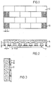
- Fig. 1 shows the element from the front
- Fig. 2 from above
- Fig. 3 from the side.
- the size of the composite element can vary within wide limits, it is preferably 0.3 to 2.0 m wide and 0.3 to 3.0 m high.
- the side of the composite element facing the building wall consists in one piece of a thermal insulation panel A, which is preferably 20 to 200 mm, in particular 30 to 120 mm thick. It is preferably made of a hard foam plastic, e.g. based on polystyrene or polyurethane, but cork or lightweight boards can also be used. According to the invention, it is provided with a plurality of ventilation ducts running vertically on the outside, in the installed state, whose depth t is preferably 10 to 50, in particular 20 to 40 mm. These ventilation ducts are milled into the thermal insulation board, whereby they can be of various shapes, e.g. undercut trapezoidal to get the largest possible adhesive surface.
- Their area proportion on the outer surface of the thermal insulation board is preferably 20 to 70 X, in particular 40 to 60 X.
- the thermal insulation board can be provided with edge folds.
- the outer surfaces of the webs recessed by the ventilation ducts are covered with the adhesive layer B, which establishes the connection to the cladding panels C.
- the usual construction adhesives and tile adhesives e.g. Dispersion adhesive or dispersion cement adhesive suitable.
- the composite element according to the invention has cladding panels C on its outside.
- These can consist of small or large-sized natural or artificial stone tiles, for example asbestos cement, asbestos cement substitutes, synthetic resin-bonded materials, ceramic tiles or split tiles.
- the joints between adjacent panels can be sealed, but they are preferably open, it being particularly advantageous if panels arranged one above the other overlap (see FIG. 3) and the edges overlap by appropriate profiling.
- the cladding panel C can have the same size as the thermal insulation panel A, is preferred However, they are much smaller, so that several cladding panels are glued to a thermal insulation panel A, which are arranged in a bandage or grid.
- the composite elements are prefabricated at the factory by gluing the thermal insulation panel A to the cladding panels C. They are attached to the building wall in one operation at the construction site so that the ventilation ducts run through the entire wall height in order to meet the requirements of DIN 18516 (draft July 1982). They are either screwed on, clamped on or preferably glued with the adhesives described above. With an offset arrangement of the individual rows of facing panels to the insulation board as an association (see Figure 1) can be a continuation of the dressing of the adjacent composite elements, wherein the completion of the association to the extended saving - are glued th edge regions subsequently facing plates.
- the external insulation with the composite elements according to the invention has the advantage over the previously ventilated, heat-insulating facade cladding that no supporting substructure is used, the composite elements can be glued to the building wall in one operation, the assembly being so simple that it can also be carried out by the handyman can be.
- the possibility of using different cladding panels results in a large variety of designs.
- the rear ventilation through the ventilation ducts ensures rapid moisture compensation and constant temperature compensation in the sense of DIN 18 516. This avoids strong and rapid temperature fluctuations that could lead to tension and detachment of the adhesive layer. If the individual cladding panels are not non-positively connected, their temperature deformation even runs independently of one another, so that practically no tensile, compressive and shear forces can build up in the composite elements from temperature-related changes in length. This is particularly pronounced with small-sized, scale-like cladding parts:
Landscapes
- Engineering & Computer Science (AREA)
- Architecture (AREA)
- Civil Engineering (AREA)
- Structural Engineering (AREA)
- Building Environments (AREA)
Abstract
Ein vorgefertigtes Verbundelement zur außenseitigen Wärmedämmung von Gebäudewänden besteht aus
- A einer Wärmedämmplatte, vorzugsweise aus einem harten Schaumkunststoff,
- B einer Klebstoffschicht und
- C Verkleidungsplatten, z.B. aus Keramik, Stein oder Asbestzement.
- A a thermal insulation board, preferably made of a hard foam plastic,
- B an adhesive layer and
- C Cladding panels, e.g. made of ceramic, stone or asbestos cement.
Die Wärmedämmplatte A ist (im Einbauzustand) außenseitig mit vertikal verlaufenden Lüftungskanälen versehen.
Description
Zur Außenisolierung von Gebäudewänden ist die Verbundfassade mit gewebearmiertem Putz am gebräuchlichsten, da sie preiswert und einfach aufzubringen ist und ein akzeptables Aussehen hat. Dabei werden Wärmedämmplatten direkt auf das Mauerwerk angebracht, die anschließend verputzt werden. Infolge Verformungsbehinderung der wärme- und schwindungsbedingten Dehnung der Wärmedämmplatten treten hohe Kräfte auf, die zur Rißsicherung ein starkes Armierungsgewebe in der Putzschicht erforderlich machen. Der Einbau ist also mit erheblichem Arbeitsaufwand verbunden. Bei Sonneneinstrahlung wird die Wandoberfläche durch Wärmestau stark aufgeheizt, was zu einer entsprechenden Beanspruchung des Verbundaufbaus führt. Ein weiterer Nachteil rührt daher, daß in der Winterperiode durch Diffusion und Kondensation an der Grenzfläche zwischen Mauerwerk und :Wärmedämmplatte Tauwasser in beträchtlichem Umfang anfallen kann, was zu einer unerwünschten Verminderung der Dämmwirkung führt.The composite facade with fabric-reinforced plaster is the most common for external insulation of building walls, as it is inexpensive and easy to apply and has an acceptable appearance. Thermal insulation boards are attached directly to the masonry, which are then plastered. As a result of the deformation of the thermal and shrinkage-related expansion of the thermal insulation panels, high forces occur, which make strong reinforcement fabric in the plaster layer necessary to prevent cracks. The installation is therefore associated with a considerable amount of work. When exposed to sunlight, the wall surface is heated up by heat build-up, which leads to a corresponding stress on the composite structure. Another disadvantage stems from the fact that in the winter period diffusion and condensation at the interface between masonry and: thermal insulation board can result in a considerable amount of condensation, which leads to an undesirable reduction in the insulation effect.
Diese Nachteile treten bei der hinterlüfteten Fassade in wesentlich geringerem Maße auf. Hier wird auf das Mauerwerk eine Unterkonstruktion aus Metallprofilen oder Holz zwischen die Dämmplatten oder über diese derart aufgebracht, daß vertikal verlaufende Lüftungsöffnungen entstehen. Auf dieser Unterkonstruktion werden Verkleidungsplatten befestigt, so daß die Feuchtigkeit in bauphysikalisch idealer Weise abgeführt wird. Das Anbringen der Unterkonstruktion ist jedoch mit erheblichen Kosten verbunden; außerdem besteht die Gefahr, daß bei Schäden oder Verlegefehlern die in der Praxis vorwiegend verwendeten Mineralfaserdämmplatten durch Schlagregen stark durchfeuchtet werden und dadurch ihre Wärmedämmfähigkeit weitgehend verlieren.These disadvantages occur to a much lesser extent with the ventilated facade. Here, a substructure made of metal profiles or wood is applied to the masonry between the insulation panels or over them in such a way that vertical ventilation openings are created. Cladding panels are attached to this substructure so that the moisture is removed in an ideal manner in terms of building physics. The installation of the substructure is associated with considerable costs; there is also the danger that damage or installation errors, the Mineralfaserdämm predominantly used in practice pale p are strongly wetted by rain, thereby largely lose its thermal insulation capability.
Der Erfindung lag nun die Aufgabe zugrunde, die Vorteile beider Isoliersysteme unter weitgehender Vermeidung der Nachteile zu vereinen.The invention was based on the object of combining the advantages of both insulation systems while largely avoiding the disadvantages.
Es wurde gefunden, daß-diese Aufgabe gelöst ist bei einem Verbundelement aus
- A einer Wärmedämmplatte,
- B einer Klebstoffschicht und
- C Verkleidungsplatten,
bei dem die Wärmedämmplatte mit im Einbauzustand außenseitig vertikal verlaufenden Lüftungskanälen versehen ist. Dd/röIt has been found that this object is achieved with a composite element
- A a thermal insulation board,
- B an adhesive layer and
- C cladding panels,
in which the thermal insulation panel is provided with ventilation ducts running vertically on the outside when installed. Dd / rö
In den Abbildungen ist das erfindungsgemäße Verbundelement skizzenhaft dargestellt. Fig. 1 zeigt das Element von vorn, Fig. 2 von oben und Fig. 3 von der Seite.The composite element according to the invention is sketched in the figures. Fig. 1 shows the element from the front, Fig. 2 from above and Fig. 3 from the side.
Die Größe des Verbundelements kann in weiten Grenzen schwanken, es ist vorzugsweise 0,3 bis 2,0 m breit und 0,3 bis 3,0 m hoch.The size of the composite element can vary within wide limits, it is preferably 0.3 to 2.0 m wide and 0.3 to 3.0 m high.
Die der Gebäudewand zugewandte Seite des Verbundelements besteht in einem Stück aus einer Wärmedämmplatte A, die vorzugsweise 20 bis 200 mm, insbesondere 30 bis 120 mm dick ist. Sie besteht vorzugsweise aus einem harten Schaumkunststoff, z.B. auf Basis von Polystyrol oder Polyurethan, es können jedoch auch Kork- oder Leichtbauplatten verwendet werden. Sie ist erfindungsgemäß mit mehreren - im Einbauzustand - außenseitig vertikal verlaufenden Lüftungskanälen versehen, deren Tiefe t vorzugsweise 10 bis 50, insbesondere 20 bis 40 mm beträgt. Diese Lüftungskanäle sind in die Wärmedämmplatte eingefräst, wobei sie verschiedenartig geformt sein können, z.B. trapezartig hinterschnitten, um eine möglichst große Klebefläche zu erhalten. Die Lüftungskanäle sind an der Außenfläche der Wärmedämmplatte vorzugsweise b = 20 bis 200 mm, insbesondere 40 bis 100 mm breit; sie weisen einen Achsabstand a voneinander von vorzugsweise 50 bis 400 mm, insbesondere von 100 bis 200 mm auf. Ihr Flächenanteil an der Außenfläche der Wärmedämmplatte beträgt vorzugsweise 20 bis 70 X, insbesondere 40 bis 60 X. Die Wärmedämmplatte kann wie üblich mit Randfalzen versehen sein.The side of the composite element facing the building wall consists in one piece of a thermal insulation panel A, which is preferably 20 to 200 mm, in particular 30 to 120 mm thick. It is preferably made of a hard foam plastic, e.g. based on polystyrene or polyurethane, but cork or lightweight boards can also be used. According to the invention, it is provided with a plurality of ventilation ducts running vertically on the outside, in the installed state, whose depth t is preferably 10 to 50, in particular 20 to 40 mm. These ventilation ducts are milled into the thermal insulation board, whereby they can be of various shapes, e.g. undercut trapezoidal to get the largest possible adhesive surface. The ventilation ducts on the outer surface of the thermal insulation panel are preferably b = 20 to 200 mm, in particular 40 to 100 mm wide; they have an axial spacing a of preferably 50 to 400 mm, in particular 100 to 200 mm. Their area proportion on the outer surface of the thermal insulation board is preferably 20 to 70 X, in particular 40 to 60 X. As usual, the thermal insulation board can be provided with edge folds.
Die Außenflächen der von den Lüftungskanälen ausgesparten Stege ist mit der Klebstoffschicht B bedeckt, welche die Verbindung zu den Verkleidungsplatten C herstellt. Als Klebstoffe sind die üblichen Baukleber und Fliesenkleber, z.B. Dispersionskleber oder Dispersionszementkleber geeignet.The outer surfaces of the webs recessed by the ventilation ducts are covered with the adhesive layer B, which establishes the connection to the cladding panels C. The usual construction adhesives and tile adhesives, e.g. Dispersion adhesive or dispersion cement adhesive suitable.
Zum Schutz der Dämmschicht gegen Witterungseinflüsse und zu Dekorationszwecken weist das erfindungsgemäße Verbundelement an seiner Außenseite Verkleidungsplatten C auf. Diese können aus kleinformatigen oder großformatigen Natur- oder Kunststein-Fliesen oder -Platten bestehen, z.B. aus Asbestzement, Asbestzementsubstituten, kunstharzgebundenen Materialien, Keramikfliesen oder Spaltplatten. Die Fugen zwischen nebeneinanderliegenden Platten können abgedichtet sein, bevorzugt sind sie aber offen, wobei es besonders günstig ist, wenn übereinander angeordnete Platten sich überlappen (siehe Figur 3) und die Ränder sich durch entsprechende Profilierung überdecken. Grundsätzlich kann die Verkleidungsplatte C die gleiche Größe haben wie die Wärmedämmplatte A, bevorzugt ist sie jedoch wesentlich kleiner, so daß auf eine Wärmedämmplatte A mehrere Verkleidungsplatten geklebt sind, die im Verband oder Raster angeordnet werden.To protect the insulation layer against the weather and for decorative purposes, the composite element according to the invention has cladding panels C on its outside. These can consist of small or large-sized natural or artificial stone tiles, for example asbestos cement, asbestos cement substitutes, synthetic resin-bonded materials, ceramic tiles or split tiles. The joints between adjacent panels can be sealed, but they are preferably open, it being particularly advantageous if panels arranged one above the other overlap (see FIG. 3) and the edges overlap by appropriate profiling. Basically, the cladding panel C can have the same size as the thermal insulation panel A, is preferred However, they are much smaller, so that several cladding panels are glued to a thermal insulation panel A, which are arranged in a bandage or grid.
Die Verbundelemente werden durch Verkleben der Wärmedämmplatte A mit den Verkleidungsplatten C werkseitig vorgefertigt. Sie werden an der Baustelle in einem Arbeitsgang an der Gebäudewand so befestigt, daß die Lüftungskanäle über die gesamte Wandhöhe durchlaufen, um die Anforderungen der DIN 18516 (Entwurf Juli 1982) zu erfüllen. Sie werden entweder angeschraubt, angeklemmt oder vorzugsweise mit den oben beschriebenen Klebern angeklebt. Bei versetzter Anordnung der einzelnen Reihen von Verkleidungsplatten auf der Wärmedämmplatte als Verband (siehe Figur 1) ist eine Weiterführung des Verbands der nebeneinanderliegenden Verbundelemente möglich, wobei zur Vervollständigung des Verbands in die ausgespar- ten Randbereiche nachträglich-Verkleidungsplatten eingeklebt werden.The composite elements are prefabricated at the factory by gluing the thermal insulation panel A to the cladding panels C. They are attached to the building wall in one operation at the construction site so that the ventilation ducts run through the entire wall height in order to meet the requirements of DIN 18516 (draft July 1982). They are either screwed on, clamped on or preferably glued with the adhesives described above. With an offset arrangement of the individual rows of facing panels to the insulation board as an association (see Figure 1) can be a continuation of the dressing of the adjacent composite elements, wherein the completion of the association to the extended saving - are glued th edge regions subsequently facing plates.
Die Außenisolierung mit den erfindungsgemäßen Verbundelementen hat gegenüber den bisher üblichen hinterlüfteten, wärmedämmenden Fassadenverkleidungen den Vorteil, daß keine tragende Unterkonstruktion gebraucht wird, die Verbundelemente können in einem Arbeitsgang auf die Gebäudewand aufgeklebt werden, wobei die Montage so einfach ist, daß sie auch vom Heimwerker ausgeführt werden kann. Die Möglichkeit, verschiedenartige Verkleidungsplatten zu verwenden, ergibt eine große Gestaltungsvielfalt.The external insulation with the composite elements according to the invention has the advantage over the previously ventilated, heat-insulating facade cladding that no supporting substructure is used, the composite elements can be glued to the building wall in one operation, the assembly being so simple that it can also be carried out by the handyman can be. The possibility of using different cladding panels results in a large variety of designs.
Die Hinterlüftung durch die Lüftungskanäle sorgt für einen schnellen Feuchtigkeitsausgleich und ständigen Temperaturausgleich im Sinne der DIN 18 516. Dadurch werden starke und schnelle Temperaturschwankungen, die zu Spannungen und Ablösung der Klebstoffschicht führen könnten, vermieden. Wenn die einzelnen Verkleidungsplatten nicht kraftschlüssig miteinander verbunden sind, verläuft ihre Temperaturverformung sogar unabhängig voneinander, so daß sich aus temperaturbedingten Längenänderungen praktisch keine Zug-, Druck- und Scherkräfte in den Verbundelementen aufbauen können. Das ist besonders ausgeprägt bei kleinformatigen, schuppenartig wirkenden Verkleidungsteilen:The rear ventilation through the ventilation ducts ensures rapid moisture compensation and constant temperature compensation in the sense of DIN 18 516. This avoids strong and rapid temperature fluctuations that could lead to tension and detachment of the adhesive layer. If the individual cladding panels are not non-positively connected, their temperature deformation even runs independently of one another, so that practically no tensile, compressive and shear forces can build up in the composite elements from temperature-related changes in length. This is particularly pronounced with small-sized, scale-like cladding parts:
Claims (5)
dadurch gekennzeichnet, daß die Wärmedämmplatte A mit (im Einbauzustand) außenseitig vertikal verlaufenden Lüftungskanälen versehen ist.1. Prefabricated composite element for external thermal insulation of building walls, consisting of
characterized in that the thermal insulation panel A is provided with (in the installed state) vertically extending ventilation ducts on the outside.
Applications Claiming Priority (2)
| Application Number | Priority Date | Filing Date | Title |
|---|---|---|---|
| DE19828234174 DE8234174U1 (en) | 1982-12-04 | 1982-12-04 | PRE-FABRIC CONNECTING ELEMENT FOR THE OUTSIDE INSULATION OF BUILDING WALLS |
| DE8234174U | 1982-12-04 |
Publications (2)
| Publication Number | Publication Date |
|---|---|
| EP0111235A2 true EP0111235A2 (en) | 1984-06-20 |
| EP0111235A3 EP0111235A3 (en) | 1985-07-03 |
Family
ID=6746234
Family Applications (1)
| Application Number | Title | Priority Date | Filing Date |
|---|---|---|---|
| EP83111891A Withdrawn EP0111235A3 (en) | 1982-12-04 | 1983-11-28 | Prefabricated composite element for the external insulation of building-walls |
Country Status (2)
| Country | Link |
|---|---|
| EP (1) | EP0111235A3 (en) |
| DE (1) | DE8234174U1 (en) |
Cited By (8)
| Publication number | Priority date | Publication date | Assignee | Title |
|---|---|---|---|---|
| EP0358164A3 (en) * | 1988-09-07 | 1990-06-06 | Steuler-Industriewerke Gmbh | Method for setting a leak indication and/or a thermal insulation gap between a wall and a lining panel as well as the application of the lining panel therefor |
| EP0273903A3 (en) * | 1986-12-30 | 1990-06-13 | RIESENEDER Gesellschaft m.b.H. u. Co. KG | Wall covering for outer- or inner surfaces of the building |
| CN102284999A (en) * | 2011-04-13 | 2011-12-21 | 赵坚强 | Anti-falling structure of decorating, heat-preserving, corrosion-resisting, abrasion-resisting and fire-preventing inorganic material product |
| ES2435091A1 (en) * | 2012-06-12 | 2013-12-18 | Emilio ORTS ARAGONÉS | Self-ventilated prefabricated facade (Machine-translation by Google Translate, not legally binding) |
| US9702152B2 (en) | 2011-06-17 | 2017-07-11 | Basf Se | Prefabricated wall assembly having an outer foam layer |
| US10801197B2 (en) | 2015-01-19 | 2020-10-13 | Basf Se | Wall assembly having a spacer |
| US11118347B2 (en) | 2011-06-17 | 2021-09-14 | Basf Se | High performance wall assembly |
| US11541625B2 (en) | 2015-01-19 | 2023-01-03 | Basf Se | Wall assembly |
Families Citing this family (2)
| Publication number | Priority date | Publication date | Assignee | Title |
|---|---|---|---|---|
| EP0204015B1 (en) * | 1985-06-04 | 1991-04-03 | BTB Bautechnische Beratung Brigitte Körner | Kit for the fabric of a thermally insulated curtain-façade |
| DE3540713A1 (en) * | 1985-11-16 | 1987-05-21 | Hans Zeidler | Wall block |
Family Cites Families (4)
| Publication number | Priority date | Publication date | Assignee | Title |
|---|---|---|---|---|
| FR918061A (en) * | 1945-11-28 | 1947-01-29 | Insulating masonry | |
| GB1097452A (en) * | 1963-11-21 | 1968-01-03 | Yoshitoshi Sohda | Wall and roof components for buildings or like constructions |
| FR2383280A1 (en) * | 1977-03-11 | 1978-10-06 | Siplast Soc Nouvelle | Roof covering with air conditioning - has channels between insulation and sealing layer for air conditioning, with solar heating |
| DE2853774C2 (en) * | 1978-12-13 | 1987-02-19 | Homapal Plattenwerk GmbH & Co KG, 3420 Herzberg | Composite panel |
-
1982
- 1982-12-04 DE DE19828234174 patent/DE8234174U1/en not_active Expired
-
1983
- 1983-11-28 EP EP83111891A patent/EP0111235A3/en not_active Withdrawn
Cited By (9)
| Publication number | Priority date | Publication date | Assignee | Title |
|---|---|---|---|---|
| EP0273903A3 (en) * | 1986-12-30 | 1990-06-13 | RIESENEDER Gesellschaft m.b.H. u. Co. KG | Wall covering for outer- or inner surfaces of the building |
| EP0358164A3 (en) * | 1988-09-07 | 1990-06-06 | Steuler-Industriewerke Gmbh | Method for setting a leak indication and/or a thermal insulation gap between a wall and a lining panel as well as the application of the lining panel therefor |
| CN102284999A (en) * | 2011-04-13 | 2011-12-21 | 赵坚强 | Anti-falling structure of decorating, heat-preserving, corrosion-resisting, abrasion-resisting and fire-preventing inorganic material product |
| US9702152B2 (en) | 2011-06-17 | 2017-07-11 | Basf Se | Prefabricated wall assembly having an outer foam layer |
| US11118347B2 (en) | 2011-06-17 | 2021-09-14 | Basf Se | High performance wall assembly |
| US11131089B2 (en) | 2011-06-17 | 2021-09-28 | Basf Se | High performace wall assembly |
| ES2435091A1 (en) * | 2012-06-12 | 2013-12-18 | Emilio ORTS ARAGONÉS | Self-ventilated prefabricated facade (Machine-translation by Google Translate, not legally binding) |
| US10801197B2 (en) | 2015-01-19 | 2020-10-13 | Basf Se | Wall assembly having a spacer |
| US11541625B2 (en) | 2015-01-19 | 2023-01-03 | Basf Se | Wall assembly |
Also Published As
| Publication number | Publication date |
|---|---|
| DE8234174U1 (en) | 1983-06-09 |
| EP0111235A3 (en) | 1985-07-03 |
Similar Documents
| Publication | Publication Date | Title |
|---|---|---|
| EP0275454B1 (en) | Synthetic sheet for an insulated wall cladding | |
| DE3108274A1 (en) | PANEL SCREEN | |
| EP0123136B1 (en) | Covering structure for floor- and wallheating | |
| EP0111235A2 (en) | Prefabricated composite element for the external insulation of building-walls | |
| DE3104955C2 (en) | ||
| DE4441646C2 (en) | Method of making a cover for balconies, patios and the like | |
| EP0682163A2 (en) | Rock wool insulating board for façades, especially for composite thermal lining systems and ventilated walls | |
| DE3519752A1 (en) | Mineral fibre product as insulating panel or insulating web | |
| DE2911579C2 (en) | ||
| DE4020685C2 (en) | Prefabricated, transportable, self-supporting tile partition | |
| DE2022140A1 (en) | Composite faced boards - with synthetic resin foam backing | |
| DE1509644A1 (en) | Sound and heat insulating leveling layer for laying dry screed | |
| DE202019105330U1 (en) | A plastic plate structure for building construction | |
| AT401078B (en) | CLADDING ELEMENT FOR FACADES | |
| AT395623B (en) | VENTILATED EXTERNAL INSULATION SYSTEM | |
| EP0207410A2 (en) | Composite elements for the exterior insulations of building walls | |
| DE810078C (en) | Lightweight panel | |
| DE3005279C2 (en) | ||
| EP1596028A2 (en) | Floor made of plates of floor cement and construction set for its generation | |
| DE102019125885A1 (en) | A plastic sheet structure for building construction | |
| DE2516954A1 (en) | Heavy rear-ventilated external wall-cladding panel fixture - with bar spacers on rear for end insertion into mortar joint gap | |
| DE102023002937A1 (en) | Prefabricated facade element, facade system and method for producing an insulated facade | |
| DE2551597A1 (en) | Ventilated external wall heat insulating cladding elements - with additional outer skin connected by cross arms, leaving ventilating channels | |
| AT364499B (en) | HEAT-INSULATING WALL PANELING | |
| DE29810269U1 (en) | Thermal insulation facade |
Legal Events
| Date | Code | Title | Description |
|---|---|---|---|
| PUAI | Public reference made under article 153(3) epc to a published international application that has entered the european phase |
Free format text: ORIGINAL CODE: 0009012 |
|
| AK | Designated contracting states |
Designated state(s): BE CH DE FR GB LI NL |
|
| PUAL | Search report despatched |
Free format text: ORIGINAL CODE: 0009013 |
|
| RHK1 | Main classification (correction) |
Ipc: E04B 1/76 |
|
| AK | Designated contracting states |
Designated state(s): BE CH DE FR GB LI NL |
|
| 17P | Request for examination filed |
Effective date: 19850504 |
|
| STAA | Information on the status of an ep patent application or granted ep patent |
Free format text: STATUS: THE APPLICATION HAS BEEN WITHDRAWN |
|
| 18W | Application withdrawn |
Withdrawal date: 19860416 |
|
| RIN1 | Information on inventor provided before grant (corrected) |
Inventor name: KRUECKAU, FRITZ ERNST |