EP0111242A2 - Anlasser für Verbrennungsmotor - Google Patents
Anlasser für Verbrennungsmotor Download PDFInfo
- Publication number
- EP0111242A2 EP0111242A2 EP83111943A EP83111943A EP0111242A2 EP 0111242 A2 EP0111242 A2 EP 0111242A2 EP 83111943 A EP83111943 A EP 83111943A EP 83111943 A EP83111943 A EP 83111943A EP 0111242 A2 EP0111242 A2 EP 0111242A2
- Authority
- EP
- European Patent Office
- Prior art keywords
- motor
- engine
- engine starter
- pinion
- ring gear
- Prior art date
- Legal status (The legal status is an assumption and is not a legal conclusion. Google has not performed a legal analysis and makes no representation as to the accuracy of the status listed.)
- Granted
Links
Images
Classifications
-
- F—MECHANICAL ENGINEERING; LIGHTING; HEATING; WEAPONS; BLASTING
- F02—COMBUSTION ENGINES; HOT-GAS OR COMBUSTION-PRODUCT ENGINE PLANTS
- F02N—STARTING OF COMBUSTION ENGINES; STARTING AIDS FOR SUCH ENGINES, NOT OTHERWISE PROVIDED FOR
- F02N7/00—Starting apparatus having fluid-driven auxiliary engines or apparatus
- F02N7/08—Starting apparatus having fluid-driven auxiliary engines or apparatus the engines being of rotary type
-
- F—MECHANICAL ENGINEERING; LIGHTING; HEATING; WEAPONS; BLASTING
- F02—COMBUSTION ENGINES; HOT-GAS OR COMBUSTION-PRODUCT ENGINE PLANTS
- F02N—STARTING OF COMBUSTION ENGINES; STARTING AIDS FOR SUCH ENGINES, NOT OTHERWISE PROVIDED FOR
- F02N11/00—Starting of engines by means of electric motors
-
- F—MECHANICAL ENGINEERING; LIGHTING; HEATING; WEAPONS; BLASTING
- F02—COMBUSTION ENGINES; HOT-GAS OR COMBUSTION-PRODUCT ENGINE PLANTS
- F02N—STARTING OF COMBUSTION ENGINES; STARTING AIDS FOR SUCH ENGINES, NOT OTHERWISE PROVIDED FOR
- F02N5/00—Starting apparatus having mechanical power storage
- F02N5/04—Starting apparatus having mechanical power storage of inertia type
-
- Y—GENERAL TAGGING OF NEW TECHNOLOGICAL DEVELOPMENTS; GENERAL TAGGING OF CROSS-SECTIONAL TECHNOLOGIES SPANNING OVER SEVERAL SECTIONS OF THE IPC; TECHNICAL SUBJECTS COVERED BY FORMER USPC CROSS-REFERENCE ART COLLECTIONS [XRACs] AND DIGESTS
- Y10—TECHNICAL SUBJECTS COVERED BY FORMER USPC
- Y10T—TECHNICAL SUBJECTS COVERED BY FORMER US CLASSIFICATION
- Y10T74/00—Machine element or mechanism
- Y10T74/13—Machine starters
Definitions
- the present invention relates to an improvement in an engine starter.
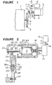
- a crank shaft 2 extends from an internal combustion engine 1 (hereinafter referred to as an engine) and a flywheel 4 with a ring gear 3 fitted at its outer circumference is secured at the free end of the crank shaft 2.
- a starter motor indicated, as a.whole, by a reference nuemral 5 is constituted by a d.c. motor 6, an overrunning clutch 7 and the rotary shaft 8 of the d.c. motor 6.
- the overrunning clutch 7, provided with a lever-engaging slot 7a has a spline-connection with the rotary shaft 8 in a slidable manner in the axial direction.
- a pinion 10 is secured to the output rotary shaft 9 so as to be capable of interlocking with the ring gear 3.
- a shift lever 11 has a pivotal point lla supported by a frame (not shown), a lower end part inserted into the lever-engaging slot 7a of the overrunning clutch 7 to be engaged therewith, and an upper end part inserted into the plunger 13 of an electromagnetic switch 12 to be engaged therewith.
- the conventional device is constructed in such a manner that the d.c. motor 6 is actuated by feeding a relatively large current from a battery (not shown) mounted on a car for each time of starting the engine 1, excessive discharge is caused in the car battery when start and stop of the engine 1 is repeated during a short time thereby inviting a rapid reduction in the starting function of the engine. Further, when the engine is restarted immediately after its stoppage, the resistance of a circuit becomes large due to a high temperature around the starting system whereby the engine sometimes could not be started.
- an engine starter comprising a d.c. motor, a pinion secured to one end of the rotary shaft of the d.c. motor, a rotary flange having a ring gear which is always interlocked with the pinion to be driven, a flywheel which is, on one hand, connected to the rotary flange through a rotational force one-way coupling clutch and is, on the other hand, firmly secured to the crank shaft of the engine, an air motor connected to the other end of the rotary shaft of the d.c. motor and an air tank communicated to the air motor through a piping, an electromagnetic valve being interposed in the piping.
- Figure 2 is a cross sectional view of an embodiment of the engine starter of the present invention.
- FIG 2 there is shown an air motor 14, for instance, of a volume type which is connected to the rotary shaft 8A of a d.c. motor 6A to be driven.
- An air tank (air reservoir) 15 is communicated to the air motor 14 through a piping 17, an electromagnetic valve 16 being interposed in the piping 17.
- a yoke 20 fitted with magnetic field poles 21 at its inner circumferential surface is clamped and secured by a rear frame 18 and a front frame 26.
- the rear frame 18 is provided with a bearing 19 which rotatably supports the rear end part of the rotary shaft 8A and the front frame 26 is provided with a sleeve bearing 27 which rotatably supports the front end part of the rotary shaft 8A.
- An armature 22 is secured to the rotary shaft so as to rotate closely facing the magnetic field poles 21.
- a pinion 23 is secured to the rotary shaft 8A and is usually interlocked with the ring gear 25 attached to the outer periphery of the rotary flange 24.
- the inner circumferential surface of the rotary flange 24 is supported by a flywheel 28 through a ball bearing 29.
- the flywheel is constructed in such a manner that a rotational force is transmitted in only one direction with respect to the rotary flange 24 by a rotational force one-way coupling clutch (an overrunning clutch) 30 which is placed in coaxial with the rotary flange 24.
- the flywheel is firmly secured to a crank shaft 2 with a hexagon headed bolt 34.
- the rotational-force one-way coupling clutch 30 is constituted by a clutch outer part 31, frictional pieces 32 and a clutch inner part 33.
- the clutch outer part 31 is fitted to a circumferential groove 28a of the flywheel 28 and the clutch inner part 33 is fitted to the rotary flange 24 respectively.
- revolution speed of the flywheel 28 becomes greater than that of the rotary flange 24.
- rotational force is not transmitted to the rotary flange 24 by the function of the rotational force one-way coupling clutch 30 and the rotary flange is subjected to non-loaded, free revolution.
- Opening of the electromagnetic valve 16 actuates the air motor for revolution and at the same time the d.c. motor is actuated by feeding current as described before.
- the rotary shaft 8A is driven by the composite torque of the air motor 14 and the armature 22 and thus produced rotational force is transmitted to the crank shaft 2 through the pinion 23, the ring gear 25 and so on, with the result that the engine 1 is restarted.
- the operation of the engine starter according to the present invention renders electric current to the d.c. motor small, hence excessive discharge of the car battery (not shown) is prevented to allow its long use. This is practically advantageous. Further, according to the embodiment of the present invention, starting of the engine with compressed air provides a satisfactory starting property even though the environmental -temperature is high at the time of restarting the engine immediately after its stoppage.
- the high temperature environment rather effects advantageously on the device of the present invention in accordance with the Charles' law that pressure of compressed air increases as temperature rises.
- Compressed air filled in the.air tank 15 may be utilized for pneumatic devices mounted on the car and waste gas having been used to start the engine may also be used to cool the engine.
- the engine starter of the present invention is so constructed that the air motor is connected to the reversible d.c. motor; the rotary shaft of the d.c. motor is usually interlocked with the ring gear connected to the crank shaft of the engine and the overrunning clutch is placed between the ring gear and the flywheel.
- the air motor is used as an air pump by making the d.c. motor reversely rotate after the engine has been started whereby compressed air is filled in the air tank by driving the pump so that the compressed air is fed to the air motor to actuate the same-at the time of restarting of the engine.
- electric current to be consumed for the d.c. motor can be small, hence a highly powerful starting device can be obtained and compressed air filled in the.air tank can be utilized for other pneumatic devices mounted on the car in a simple construction and at low cost.
Landscapes
- Engineering & Computer Science (AREA)
- Chemical & Material Sciences (AREA)
- Combustion & Propulsion (AREA)
- Mechanical Engineering (AREA)
- General Engineering & Computer Science (AREA)
- Connection Of Motors, Electrical Generators, Mechanical Devices, And The Like (AREA)
- Testing Of Engines (AREA)
Applications Claiming Priority (2)
| Application Number | Priority Date | Filing Date | Title |
|---|---|---|---|
| JP183899/82U | 1982-12-03 | ||
| JP1982183899U JPS5988273U (ja) | 1982-12-03 | 1982-12-03 | 機関始動装置 |
Publications (3)
| Publication Number | Publication Date |
|---|---|
| EP0111242A2 true EP0111242A2 (de) | 1984-06-20 |
| EP0111242A3 EP0111242A3 (en) | 1984-07-18 |
| EP0111242B1 EP0111242B1 (de) | 1987-03-04 |
Family
ID=16143755
Family Applications (1)
| Application Number | Title | Priority Date | Filing Date |
|---|---|---|---|
| EP83111943A Expired EP0111242B1 (de) | 1982-12-03 | 1983-11-29 | Anlasser für Verbrennungsmotor |
Country Status (4)
| Country | Link |
|---|---|
| US (1) | US4543923A (de) |
| EP (1) | EP0111242B1 (de) |
| JP (1) | JPS5988273U (de) |
| DE (1) | DE3370057D1 (de) |
Cited By (2)
| Publication number | Priority date | Publication date | Assignee | Title |
|---|---|---|---|---|
| DE19529740A1 (de) * | 1995-08-12 | 1997-02-13 | Bayerische Motoren Werke Ag | Brennkraftmaschine mit einer elektrischen Anlaßeinrichtung |
| CN102817758A (zh) * | 2011-06-09 | 2012-12-12 | 福特环球技术公司 | 用于重新起动发动机的设备和方法 |
Families Citing this family (20)
| Publication number | Priority date | Publication date | Assignee | Title |
|---|---|---|---|---|
| FR2598753B1 (fr) * | 1986-05-16 | 1988-08-26 | Valeo | Dispositif de demarrage pour moteur a combustion interne |
| JP2566398B2 (ja) * | 1986-11-19 | 1996-12-25 | 本田技研工業株式会社 | エンジンの調時伝動装置 |
| JPH01150070A (ja) * | 1987-12-04 | 1989-06-13 | Mitsubishi Electric Corp | プーリおよびその製造方法 |
| US5086746A (en) * | 1991-03-29 | 1992-02-11 | General Motors Corporation | Compressed air supply |
| FR2709617B1 (fr) * | 1993-09-02 | 1995-09-29 | Gec Alsthom Transport Sa | Ensemble moto-réducteur. |
| US6089112A (en) * | 1998-02-06 | 2000-07-18 | Case Corporation | Method and apparatus for starting an engine |
| JP2001065441A (ja) * | 1999-08-27 | 2001-03-16 | Hitachi Ltd | 内燃機関用始動装置 |
| RU2239090C2 (ru) * | 2001-05-28 | 2004-10-27 | Горский государственный аграрный университет | Система электростартерного пуска двигателя внутреннего сгорания |
| DE102005019507A1 (de) * | 2005-04-27 | 2006-11-02 | Zf Friedrichshafen Ag | Vorrichtung zur kuppelbaren Verbindung der Schwungscheibe eines Antriebsmotors mit einer Abtriebswelle |
| US8319356B2 (en) * | 2008-08-26 | 2012-11-27 | Caterpillar Inc. | System for starting power systems with multiple generator units |
| US20160102643A9 (en) * | 2008-08-26 | 2016-04-14 | Progress Rail Services Corp. | System for starting power systems with multiple generator units |
| US8166753B2 (en) * | 2008-11-24 | 2012-05-01 | Robert Bosch Gmbh | Accumulator system and method of monitoring same |
| US8302720B2 (en) * | 2009-01-28 | 2012-11-06 | Robert Bosch Gmbh | Energy storage system for a hybrid vehicle |
| US8186155B2 (en) * | 2009-01-30 | 2012-05-29 | Robert Bosch Gmbh | Hydraulic energy storage system with accumulator and method of varying charge of same |
| US7913791B2 (en) | 2009-05-04 | 2011-03-29 | Robert Bosch Gmbh | Energy storage system for a hybrid vehicle |
| JP5628714B2 (ja) * | 2011-03-11 | 2014-11-19 | 日立オートモティブシステムズ株式会社 | 車両用エンジン始動装置 |
| DE102011081093A1 (de) * | 2011-08-17 | 2013-02-21 | Robert Bosch Gmbh | Startsystem, Verfahren und Computerprogrammprodukt zum Starten einer Brennkraftmaschine |
| DE102016115904B4 (de) * | 2015-08-27 | 2017-12-07 | Denso Corporation | Anlasser für Maschine |
| CN106089534B (zh) * | 2016-06-29 | 2019-01-25 | 南昌天元汽车配件工业有限公司 | 一种起动机 |
| EP4208638A4 (de) * | 2020-09-04 | 2024-06-19 | Volvo Truck Corporation | Steuerungsverfahren, steuergerät und steuerungsprogramm zur steuerung eines startsystems, computerlesbares medium mit dem steuerungsprogramm, startsystem und fahrzeug |
Family Cites Families (8)
| Publication number | Priority date | Publication date | Assignee | Title |
|---|---|---|---|---|
| US1196156A (en) * | 1916-08-29 | Albert c | ||
| US973232A (en) * | 1909-07-29 | 1910-10-18 | N E Woessner | Starting device for automobiles and like machines. |
| US1124736A (en) * | 1910-01-12 | 1915-01-12 | A E L Leckie | Gas-engine starting and generating apparatus. |
| US1364853A (en) * | 1912-06-19 | 1921-01-04 | Mastrangel | Engine-starter |
| FR771993A (fr) * | 1933-04-22 | 1934-10-20 | Bosch Robert | Dispositif de démarrage pour moteurs |
| FR1105307A (fr) * | 1954-05-25 | 1955-11-29 | Air Equipement | Perfectionnements aux moto-démarreurs à inertie |
| DE2853130A1 (de) * | 1978-12-08 | 1980-06-19 | Luk Lamellen & Kupplungsbau | Einrichtung zum starten einer brennkraftmaschine |
| US4235216A (en) * | 1979-02-26 | 1980-11-25 | Miles Norval W | Auxiliary starter mechanism for automobile engines and the like |
-
1982
- 1982-12-03 JP JP1982183899U patent/JPS5988273U/ja active Pending
-
1983
- 1983-11-17 US US06/552,840 patent/US4543923A/en not_active Expired - Fee Related
- 1983-11-29 DE DE8383111943T patent/DE3370057D1/de not_active Expired
- 1983-11-29 EP EP83111943A patent/EP0111242B1/de not_active Expired
Cited By (5)
| Publication number | Priority date | Publication date | Assignee | Title |
|---|---|---|---|---|
| DE19529740A1 (de) * | 1995-08-12 | 1997-02-13 | Bayerische Motoren Werke Ag | Brennkraftmaschine mit einer elektrischen Anlaßeinrichtung |
| CN102817758A (zh) * | 2011-06-09 | 2012-12-12 | 福特环球技术公司 | 用于重新起动发动机的设备和方法 |
| GB2491627A (en) * | 2011-06-09 | 2012-12-12 | Ford Global Tech Llc | An apparatus and method for restarting an engine |
| CN102817758B (zh) * | 2011-06-09 | 2017-06-13 | 福特环球技术公司 | 用于重新起动发动机的设备和方法 |
| GB2491627B (en) * | 2011-06-09 | 2017-07-26 | Ford Global Tech Llc | An apparatus and method for restarting an engine |
Also Published As
| Publication number | Publication date |
|---|---|
| DE3370057D1 (en) | 1987-04-09 |
| US4543923A (en) | 1985-10-01 |
| JPS5988273U (ja) | 1984-06-14 |
| EP0111242A3 (en) | 1984-07-18 |
| EP0111242B1 (de) | 1987-03-04 |
Similar Documents
| Publication | Publication Date | Title |
|---|---|---|
| US4543923A (en) | Engine starter | |
| US6378479B1 (en) | Starting system for internal combustion engine | |
| KR100718670B1 (ko) | 링기어와 피니언의 결합 안정성이 향상되도록 설계된 엔진스타터 | |
| US7305899B2 (en) | Starter with stopper on clutch inner portion of one-way clutch | |
| US7219569B2 (en) | Integral one-way overrun clutch with epcicycle gear system | |
| US5195389A (en) | Planetary speed reduction gear type starter | |
| US4559455A (en) | Accessory carrying type starting motor | |
| US6466116B1 (en) | Starter motor | |
| US5154089A (en) | Coaxial type starter | |
| US4621197A (en) | Multi-function starter | |
| US3714834A (en) | Engine starting gearing | |
| US4553441A (en) | Starting system for internal combustion engine | |
| EP0115852B1 (de) | Anlassvorrichtung | |
| US4884535A (en) | Starting system for internal combustion engine | |
| KR20050065336A (ko) | 엔진 스타터 | |
| US6679213B2 (en) | Starter arrangement and method for an engine | |
| EP0109246B1 (de) | Anlassvorrichtung für Verbrennungsmotor | |
| US6895915B2 (en) | Direct drive cranking system for belt or chain-driven V-Twin motorcycle engines | |
| US6870278B2 (en) | Starter for internal combustion engines | |
| KR940009055B1 (ko) | 동축형 스타터 | |
| JPS643787Y2 (de) | ||
| EP1258631A2 (de) | Brennkraftmaschinenstartermotor und Verfahren | |
| JP3873749B2 (ja) | 中間歯車付スタータ | |
| KR100405439B1 (ko) | 엔진스타터 | |
| JPH0234467Y2 (de) |
Legal Events
| Date | Code | Title | Description |
|---|---|---|---|
| PUAI | Public reference made under article 153(3) epc to a published international application that has entered the european phase |
Free format text: ORIGINAL CODE: 0009012 |
|
| PUAL | Search report despatched |
Free format text: ORIGINAL CODE: 0009013 |
|
| AK | Designated contracting states |
Designated state(s): DE FR GB |
|
| AK | Designated contracting states |
Designated state(s): DE FR GB |
|
| 17P | Request for examination filed |
Effective date: 19841004 |
|
| GRAA | (expected) grant |
Free format text: ORIGINAL CODE: 0009210 |
|
| AK | Designated contracting states |
Kind code of ref document: B1 Designated state(s): DE FR GB |
|
| REF | Corresponds to: |
Ref document number: 3370057 Country of ref document: DE Date of ref document: 19870409 |
|
| ET | Fr: translation filed | ||
| PLBE | No opposition filed within time limit |
Free format text: ORIGINAL CODE: 0009261 |
|
| STAA | Information on the status of an ep patent application or granted ep patent |
Free format text: STATUS: NO OPPOSITION FILED WITHIN TIME LIMIT |
|
| 26N | No opposition filed | ||
| PGFP | Annual fee paid to national office [announced via postgrant information from national office to epo] |
Ref country code: FR Payment date: 19921109 Year of fee payment: 10 |
|
| PGFP | Annual fee paid to national office [announced via postgrant information from national office to epo] |
Ref country code: GB Payment date: 19921117 Year of fee payment: 10 |
|
| PGFP | Annual fee paid to national office [announced via postgrant information from national office to epo] |
Ref country code: DE Payment date: 19921212 Year of fee payment: 10 |
|
| PG25 | Lapsed in a contracting state [announced via postgrant information from national office to epo] |
Ref country code: GB Effective date: 19931129 |
|
| GBPC | Gb: european patent ceased through non-payment of renewal fee |
Effective date: 19931129 |
|
| PG25 | Lapsed in a contracting state [announced via postgrant information from national office to epo] |
Ref country code: FR Effective date: 19940729 |
|
| PG25 | Lapsed in a contracting state [announced via postgrant information from national office to epo] |
Ref country code: DE Effective date: 19940802 |
|
| REG | Reference to a national code |
Ref country code: FR Ref legal event code: ST |