EP0111271A1 - Leitungsrohr aus Kunststoff, insbesondere für Abwässer - Google Patents
Leitungsrohr aus Kunststoff, insbesondere für Abwässer Download PDFInfo
- Publication number
- EP0111271A1 EP0111271A1 EP83112119A EP83112119A EP0111271A1 EP 0111271 A1 EP0111271 A1 EP 0111271A1 EP 83112119 A EP83112119 A EP 83112119A EP 83112119 A EP83112119 A EP 83112119A EP 0111271 A1 EP0111271 A1 EP 0111271A1
- Authority
- EP
- European Patent Office
- Prior art keywords
- pipe
- sleeve
- pushed
- diameter
- tube
- Prior art date
- Legal status (The legal status is an assumption and is not a legal conclusion. Google has not performed a legal analysis and makes no representation as to the accuracy of the status listed.)
- Granted
Links
- 239000010865 sewage Substances 0.000 title claims abstract description 7
- 238000004026 adhesive bonding Methods 0.000 claims abstract description 8
- 238000003466 welding Methods 0.000 claims abstract description 7
- 238000007789 sealing Methods 0.000 claims description 5
- 239000000853 adhesive Substances 0.000 claims description 3
- 230000001070 adhesive effect Effects 0.000 claims description 3
- 239000002131 composite material Substances 0.000 description 6
- 238000004519 manufacturing process Methods 0.000 description 4
- 239000002351 wastewater Substances 0.000 description 3
- 238000001125 extrusion Methods 0.000 description 2
- 239000003292 glue Substances 0.000 description 2
- 238000003780 insertion Methods 0.000 description 2
- 230000037431 insertion Effects 0.000 description 2
- 239000007788 liquid Substances 0.000 description 2
- 239000000463 material Substances 0.000 description 2
- 229910052572 stoneware Inorganic materials 0.000 description 2
- 230000007704 transition Effects 0.000 description 2
- 244000089486 Phragmites australis subsp australis Species 0.000 description 1
- 230000007547 defect Effects 0.000 description 1
- 210000003027 ear inner Anatomy 0.000 description 1
- 239000012530 fluid Substances 0.000 description 1
- 238000000034 method Methods 0.000 description 1
- 238000000465 moulding Methods 0.000 description 1
- 238000007493 shaping process Methods 0.000 description 1
Images

Classifications
-
- F—MECHANICAL ENGINEERING; LIGHTING; HEATING; WEAPONS; BLASTING
- F16—ENGINEERING ELEMENTS AND UNITS; GENERAL MEASURES FOR PRODUCING AND MAINTAINING EFFECTIVE FUNCTIONING OF MACHINES OR INSTALLATIONS; THERMAL INSULATION IN GENERAL
- F16L—PIPES; JOINTS OR FITTINGS FOR PIPES; SUPPORTS FOR PIPES, CABLES OR PROTECTIVE TUBING; MEANS FOR THERMAL INSULATION IN GENERAL
- F16L25/00—Construction or details of pipe joints not provided for in, or of interest apart from, groups F16L13/00 - F16L23/00
- F16L25/0036—Joints for corrugated pipes
-
- F—MECHANICAL ENGINEERING; LIGHTING; HEATING; WEAPONS; BLASTING
- F16—ENGINEERING ELEMENTS AND UNITS; GENERAL MEASURES FOR PRODUCING AND MAINTAINING EFFECTIVE FUNCTIONING OF MACHINES OR INSTALLATIONS; THERMAL INSULATION IN GENERAL
- F16L—PIPES; JOINTS OR FITTINGS FOR PIPES; SUPPORTS FOR PIPES, CABLES OR PROTECTIVE TUBING; MEANS FOR THERMAL INSULATION IN GENERAL
- F16L47/00—Connecting arrangements or other fittings specially adapted to be made of plastics or to be used with pipes made of plastics
- F16L47/06—Connecting arrangements or other fittings specially adapted to be made of plastics or to be used with pipes made of plastics with sleeve or socket formed by or in the pipe end
-
- F—MECHANICAL ENGINEERING; LIGHTING; HEATING; WEAPONS; BLASTING
- F16—ENGINEERING ELEMENTS AND UNITS; GENERAL MEASURES FOR PRODUCING AND MAINTAINING EFFECTIVE FUNCTIONING OF MACHINES OR INSTALLATIONS; THERMAL INSULATION IN GENERAL
- F16L—PIPES; JOINTS OR FITTINGS FOR PIPES; SUPPORTS FOR PIPES, CABLES OR PROTECTIVE TUBING; MEANS FOR THERMAL INSULATION IN GENERAL
- F16L9/00—Rigid pipes
- F16L9/12—Rigid pipes of plastics with or without reinforcement
- F16L9/133—Rigid pipes of plastics with or without reinforcement the walls consisting of two layers
-
- Y—GENERAL TAGGING OF NEW TECHNOLOGICAL DEVELOPMENTS; GENERAL TAGGING OF CROSS-SECTIONAL TECHNOLOGIES SPANNING OVER SEVERAL SECTIONS OF THE IPC; TECHNICAL SUBJECTS COVERED BY FORMER USPC CROSS-REFERENCE ART COLLECTIONS [XRACs] AND DIGESTS
- Y10—TECHNICAL SUBJECTS COVERED BY FORMER USPC
- Y10S—TECHNICAL SUBJECTS COVERED BY FORMER USPC CROSS-REFERENCE ART COLLECTIONS [XRACs] AND DIGESTS
- Y10S285/00—Pipe joints or couplings
- Y10S285/903—Corrugated
Definitions
- the invention relates to a conduit made of plastic for nominal widths over 200 mm, in particular sewage pipe, with a separate smooth inner pipe and a transversely corrugated outer pipe, which are pushed into each other so that the troughs of the outer pipe lie essentially against the outside of the inner pipe, and with Connection means at the ends for connecting several line pipes to one pipe via a socket connection.
- Such a conduit has become known, for example, in DE-OS 28 40 174 or US Pat. No. 4,037,676.
- the inner tube is widened like a sleeve at one end.
- expansion is not without problems.
- the special advantage of the double tube is, however, that the inner tube can have a very small wall thickness and is only used for flow conduction. The pressure load from outside is taken over by the corrugated outer tube. The widening at one end to form a sleeve therefore requires that the wall thickness of the inner tube must not fall below a certain value.
- a further difficulty with composite or double pipes of the type mentioned at the outset is that the outer dimensions of the inner pipes no longer fall below the standardized dimensions which are normally specified for such pipes. It is conceivable to expand the sleeve to a nominal width that corresponds to the outer diameter of the inner tube. In such a case, however, it is not possible to connect the composite pipe to conventional conduits, which e.g. are made in one piece from plastic or stoneware and have standardized dimensions.
- the invention is therefore based on the object of creating a conduit for a pipeline in the form of a composite pipe which is simple to produce and with conventional stan dardized conduits can be easily connected.
- the inner tube has smooth cylindrical end portions projecting beyond the ends of the outer tube, onto which a cylindrical sleeve with a predetermined outer diameter is pushed and fastened by welding and / or gluing.
- the inner tube is extruded in the invention. However, it remains smoothly cylindrical. The production of the inner tube is therefore particularly simple and inexpensive.
- Cylindrical sleeves are pushed onto the smooth ends that protrude beyond the outer tube and attached to the inner tube by welding and / or gluing.
- the ends of a conduit according to the invention are therefore of the same design. Each end can therefore be inserted into a socket of a conventional conduit, e.g. for wastewater. If several line pipes according to the invention are assembled to form a line, commercially available pipe sleeves made of plastic can be used, which are pushed onto both sleeves of line pipes which abut one another.
- the invention has the further advantage that the inner tube only has to be given a wall thickness such as that required for its function, i.e. Line of a fluid medium is needed.
- the production of the conduit according to the invention can be accomplished with little manufacturing effort.
- the application and fixing of the separate sleeves, which are pushed onto the ends of the inner tube, can be carried out with simple means.
- the sleeves have an inward-pointing shoulder or radial flange which lies against the free end of the inner tube and has a bevel on the outside relative to the flange.
- the ends of the corrugated outer tube bear against the facing end faces of the sleeves, preferably engage in a recess which is formed by a beveling of the sleeve and the inner tube.
- the bevel enables easier insertion of the pipes into a connecting sleeve.
- a pipe can be formed in a simple manner with the help of the line pipes according to the invention, wob E a separate connecting sleeve is provided with two axially spaced ring grooves for receiving a sealing ring, which can be pushed onto both abutting sleeves of connecting pipes to be connected.
- Such connecting sleeves are commercially available components and are used, for example, if for some reason an interruption must be made in the course of a pipeline, which is then eliminated again.
- Another possibility of connecting the composite pipe according to the invention with conventional standardized conduit pipes of the same nominal size is to slide a sleeve onto the projecting end of the inner pipe and to expand the projecting end together with the sleeve into a sleeve, the inside diameter of which, in a known manner, corresponds to the outside diameter of the standardized one Rohres corresponds. A sleeve is then pushed onto the other end of the inner tube in the manner described above, so that the inner tube reaches the standard outer diameter.
- a sleeve made of plastic can be designed so that it is pushed onto the projecting end of the inner tube and attached to it.
- a plastic sleeve with a larger wall thickness can be molded onto an extruded inner tube.
- a sleeve can in turn be applied to the other projecting end of the inner tube in the manner described above.
- the sleeve is preferably attached by gluing. This can e.g. happen in such a way that glue is previously applied to the surfaces to be joined.
- An alternative according to the invention provides for at least two holes to be provided in the sleeve at an axial distance. The holes are connected on the inside with ring grooves, which in turn are connected to each other by narrow channels. In this way, liquid adhesive can be pressed in through an opening and distributed over the circumference. The other opening is for the air to escape.
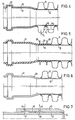
- Fig. 1 partially shows a composite tube, consisting of a smooth cylindrical inner tube 10 made of plastic and a corrugated tube 11 arranged thereon, also made of plastic.
- the inner tube 10 is extruded smooth cylindrical in a known manner.
- the corrugated tube 11 is produced in a known manner by extrusion and subsequent shaping.
- Inner and outer tubes 10, 11 are telescopically joined, the valleys 12 of the outer tube more or less against the outside of the inner tube 10 come to rest. Furthermore, the valleys can be spot welded to the inner tube in order to obtain an axial securing relative to one another.
- the inner tube 10 projects at both ends over the outer tube 11 by a section 13 onto which a cylindrical sleeve 14 is pushed.
- the sleeve 14 has an inwardly facing racial collar 15 at one end, which comes to rest against the end face of the inner ear 10; 1, collar 15 and inner tube 10 have the same inner diameter. As a result, the sleeve 14 is automatically positioned on the inner tube 10 during the production of the tube shown.
- the sleeve 14 also has a chamfer 16 on the outside at the free end that an annular recess is formed, in which the valley of the corrugation 11 can engage with its front end.
- the outer diameter of the sleeve 14 corresponds to the outer diameter of standard pipes for waste water.
- the inner tube 10 is designed with a relatively thin wall.
- the inner tube 10 need not be designed for compressive forces, since these are only absorbed by the outer tube 11. (This means external pressure forces, since there is no significant internal pressure in waste water or it is not permitted.)
- the other end of the tube partially shown in Fig. 1 is constructed in the same way, so that a pipe connection according to Fi g . 2 can be produced.
- a cylindrical sleeve 17 is slid onto the outside of the cylindrical sleeves 14, 14 'and has annular extensions' 18 and 19 at an axial distance, whereby annular grooves 20, 21 are formed.
- the ring grooves 20, 21 take up 0-sealing rings 22 and 23, respectively.
- the sealing rings 22, 23 come to lie against the outside of the sleeves 14, 14 '.
- a conventional one-piece conduit 24 made of stoneware or plastic is shown that is single-walled and accordingly has a considerable wall thickness.
- the tube 24 is widened at one end to form a sleeve 25, the inside diameter of which corresponds to the outside diameter of the tube 24. Since an abrupt transition during expansion cannot be achieved for material reasons, a conical section 26 is provided between the pipe 24 and the sleeve 25.
- An annular extension 27 of the sleeve 25 forms a groove 28 for receiving a sealing ring 29.
- the sleeve 14 has, as already mentioned, the outside diameter of a corresponding standard sewer pipe and can therefore be inserted into the sleeve 25 in a suitable manner.
- the bevel 16 comes to lie against the inside of the conical section 26, so that there is an insertion limitation.
- a sleeve 32 is pushed onto the projecting end 31 of the inner tube 10.
- the sleeve 32 is also provided at the front end with a collar 34, against the shoulder of which the end face of the inner tube section 31 abuts. Since the inner diameter of the collar 34 and the inner tube 31 are the same, a continuous transition of the same diameter is formed. As can also be seen, a wave trough can again engage in the recess at the rear end of the sleeve 32.
- an outer tube 11 is used in the manner described above.
- the inner tube 40 is formed over the length of the outer tube 11 with the same wall thickness as the inner tube 10 according to the above statements.
- it has a sleeve 41 integrally formed on it, which e.g. after extrusion can be molded onto the inner tube 40.
- the inner tube 40 and sleeve 41 are in one piece.
- the dimensions of the sleeve 41 correspond in turn to the sleeves of the above embodiments.
- a sleeve is expediently placed on the other end of the inner tube 10, which also has a projecting section pushed, which corresponds approximately to the sleeve of FIG. 1, so that the standardized outer diameter is reached.
- FIG. 7 shows a part in section of an inner tube with the section 42 projecting over the outer tube, a sleeve 43 being pushed on in a manner similar to the embodiment according to FIG. 1.
- the sleeve 43 in turn has a radial collar 44.
- the sleeve has two axially spaced through holes 45, 46 which widen approximately outwards. On the inside, they are connected with annular grooves 47, 48 on the inside of the sleeve 43. Between the ring grooves 47, 48, the sleeve is slightly enlarged in diameter, so that an axial channel 49 results.
- a plurality of pairs of holes 45, 46 can be arranged over the circumference of the sleeve 43. It is further understood that, instead of the circumferential annular groove 49, a plurality of axial channels spaced apart in the circumferential direction can be provided.
- the sleeve 43 can be mechanically glued to the inner tube 42 in a simple manner.
- liquid glue is pressed into the hole 45.
- the escaping air flows out through the opening 46.
- the adhesive may be e-rich spread over a large B of the sleeve and harden. In this way, the sleeve 43 is securely attached to the inner tube section 42.
- the wave crests are wider than the ratio lies wave troughs, wherein the V ER- 1.5 to 2.6.
- the wall thickness of the crests of the wave crests is less than the thickness in the foot of the valleys. This ratio is preferably between 1.1 and 2.1. In Fig. 4, these thicknesses are denoted by d S and d F.
- the widths are denoted by b B and bT.
- the flanks of the valleys or wave crests are extremely steep and almost perpendicular to the axis of the pipe.
- the angle to the vertical is between 2 and 8 °. It is essentially a draft angle.
Landscapes
- Engineering & Computer Science (AREA)
- General Engineering & Computer Science (AREA)
- Mechanical Engineering (AREA)
- Rigid Pipes And Flexible Pipes (AREA)
Abstract
Description
- Die Erfindung bezieht sich auf ein Leitungsrohr aus Kunststoff für Nennweiten über 200 mm,insbesondere Abwasserrohr, mit einem getrennten glatten Innenrohr und einem quer gewellten Außenrohr, die so ineinandergeschoben sind, daß die Wellentäler des Außenrohres im wesentlichen an der Außenseite des Innenrohres anliegen, und mit Verbindungsmitteln an den Enden zur Verbindung mehrerer Leitungsrohre zu einer Rohrleitung über eine Muffenverbindung.
- Ein derartiges Leitungsrohr ist etwa in der DE-OS 28 40 174 oder der US-PS 4 037 676 bekanntgeworden. Das Innenrohr ist an einem Ende muffenartig aufgeweitet. Eine derartige Aufweitung ist jedoch nicht unproblematisch. Zum einen erfordert sie einen getrennten Formvorgang. Zum anderen besteht Gefahr, daß bei zu geringer Wandstärke des Innenrohrs ein Aufweiten zu Materialfehlern führt. Der besondere Vorzug des Doppelrohres ist jedoch, daß das Innenrohr sehr geringe Wanddicke haben kann und nur zur Strömungsleitung dient. Die Druckbelastung von außen wird vom gewellten Außenrohr übernommen. Das Aufweiten an einem Ende zur Bildung einer Muffe bedingt daher, daß die Wandstärke des Innenrohres einen bestimmten Wert nicht unterschreiten darf.
- Eine weitere Schwierigkeit bei Verbund- oder Doppelrohren der eingangs genannten Art besteht darin, daß die Außenabmessungen der Innenrohre nicht mehr unter die genormten Abmessungen fallen, die für derartige Rohrleitungen normalerweise vorgegeben sind. Es ist zwar denkbar, die Muffe auf eine Nennweite zu erweitern, die dem Außendurchmesser des Innenrohres entspricht. In einem solchen Fall ist es jedoch nicht möglich, das Verbundrohr mit herkömmlichen Leitungsrohren zu verbinden, die z.B. einteilig aus Kunststoff oder Steinzeug gefertigt sind und die genormte Abmessungen haben.
- Der Erfindung liegt daher die Aufgabe zugrunde, für eine Rohrleitung ein Leitungsrohr in Form eines Verbundrohres zu schaffen, das einfach herstellbar ist und mit herkömmlichen, standardisierten Leitungsrohren ohne weiteres verbunden werden kann.
- Diese Aufgabe wird erfindungsgemäß dadurch gelöst, daß das Innenrohr über die Enden des Außenrohres überstehende, glatt zylindrische Endabschnitte aufweist, auf die eine zylindrische Hülse mit vorgegebenem Außendurchmesser geschoben und durch Schweißung und/oder Klebung befestigt ist.
- Wie bei dem bekannten Leitungsrohr wird auch bei der Erfindung das Innenrohr extrudiert. Es bleibt jedoch glatt zylindrisch. Die Herstellung des Innenrohres gestaltet sich daher besonders einfach und unaufwendig.
- Auf die glatten Enden, die über das Außenrohr überstehen, werden jeweils zylindrische Hülsen aufgeschoben und durch Schweißung und/oder Klebung am Innenrohr befestigt. Die Enden eines erfindungsgemäßen Leitungsrohres sind daher gleich ausgebildet. Jedes Ende kann daher in eine Muffe eines herkömmlichen Leitungsrohres, z.B. für Abwasser, eingesetzt werden. Werden mehrere erfindungsgemäße Leitungsrohre zu einer Leitung zusammengesetzt, können handelsübliche Rohrmuffen aus Kunststoff verwendet werden, die auf beide Hülsen aneinanderstoßender Leitungsrohre aufgeschoben werden.
- Die Erfindung hat den weiteren Vorteil, daß dem Innenrohr lediglich eine Wandstärke gegeben werden muß, wie sie für seine Funktion, d.h. Leitung eines fluiden Mediums, benötigt wird. Die Herstellung des erfindungsgemäßen Leitungsrohres ist mit geringem Fertigungsaufwand zu bewerkstelligen. Das Aufbringen und Fixieren der getrennten Hülsen, die auf die Enden des Innenrohres aufgeschoben werden, ist mit einfachen Mitteln durchführbar.
- Nach einer Ausgestaltung der Erfindung ist vorgesehen, daß die Hülsen einen nach innen weisenden Absatz oder radialen Flansch aufweisen, der sich gegen das freie Ende des Innenrohres legt und gegenüber dem Flansch-an der Außenseite eine Anschrägung aufweisen.
- Nach einer weiteren Ausgestaltung der Erfindung ist vorgesehen, daß die Enden des gewellten Außenrohres gegen die zugewandten Stirnseiten der Hülsen anliegen, vorzugsweise in eine Ausnehmung eingreifen, die durch eine Anschrägung der Hülse und dem Innenrohr gebildet ist. Die Anschrägung ermöglicht ein erleichtertes Einschieben der Rohre in eine Verbindungsmuffe.
- Wie erwähnt, kann mit Hilfe der erfindungsgemäßen Leitungsrohre auf einfache Weise eine Rohrleitung gebildet werden, wobE eine getrennte Verbindungsmuffe vorgesehen wird mit zwei axial beabstandeten Ringnuten zur Aufnahme eines Dichtringes, welche auf beide aneinanderstoßende Hülsen zu verbindender Leitungsrohre aufschiebbar ist. Derartige Verbindungsmuffen sind an sich handelsübliche Bauteile und werden zum Beispiel eingesetzt, wenn aus irgendwelchen Gründen im Zuge einer Rohrleitung eine Unterbrechung vorgenommen werden muß, die anschließend wieder beseitigt wird.
- Eine andere Möglichkeit, das erfindungsgemäße Verbundrohr mit herkömmlichen standardisierten Leitungsrohren gleicher Nennweite zu verbinden, besteht darin, auf das überstehende Ende des Innenrohres eine Hülse aufzuschieben und das überstehende Ende zusammen mit der Hülse zu einer Muffe aufzuweiten, deren Innendurchmesser in bekannter Weise dem Außendurchmesser des standardisierten Rohres entspricht. Auf das andere Ende des Innenrohres wird dann in der oben beschriebenen Weise eine Hülse aufgeschoben, damit das Innenrohr den Standardaußendurchmesser erreicht.
- Bei einer dritten Lösungsmöglichkeit kann eine Muffe aus Kunststoff so ausgebildet werden, daß sie auf das überstehende Ende des Innenrohres aufgeschoben und daran befestigt wird.
- Schließlich kann an ein extrudiertes Innenrohr eine Kunststoffmuffe mit größerer Wandstärke angespritzt werden. In beiden zuiletzt genannten Fällen kann wiederum auf das andere überstehende Ende des Innenrohres eine Hülse in oben beschriebener Weise aufgebracht werden.
- Die Hülse wird vorzugsweise durch Klebung befestigt. Dies kann z.B. in der Weise geschehen, daß auf die miteinander zu verbindenden Flächen vorher Klebstoff aufgetragen wird. Eine erfindungsgemäße Alternative sieht vor, in axialem Abstand mindestens zwei Löcher in der Hülse vorzusehen. Die Löcher sind an der Innenseite mit Ringnuten in Verbindung, die ihrerseits durch schmale Kanäle miteinander verbunden sind. Auf diese Weise kann flüssiger Klebstoff über die eine Öffnung eingedrückt werden und sich über den Umfang verteilen. Die andere Öffnung dient zum Entweichen der Luft.
- Ausführungsbeispiele der Erfindung werden nachfolgend anhand von Zeichnungen näher erläutert.
-
- Fig. 1 zeigt einen Schnitt durch einen Teil eines Endes eines Leitungsrohres nach der Erfindung.
- Fig. 2 zeigt im Schnitt eine Verbindung von zwei Leitungsrohren nach der Erfindung.
- Fig. 3 zeigt einen Schnitt durch die Verbindung eines Leitungsrohres nach der Erfindung mit einem herkömmlichen Rohr.
- Fig. 4 zeigt im Schnitt das Ende eines erfindungsgemäßen Leitungsrohres in einer zweiten Ausführungsform.
- Fig. 5- zeigt einen Schnitt durch das Ende eines erfindungsgemäßen Leitungsrohres in. einer dritten Ausführungsform.
- Fig. 6 zeigt im Schnitt das Ende eines erfindungsgemäßen Leitungsrohres in einer vierten Ausführungsform.
- Fig. 7 zeigt einen Schnitt durch ein Ende eines erfindungsgemäßen Leitungsrohres mit einer Möglichkeit zur Verklebung.
- Fig. 1 zeigt teilweise ein Verbundrohr, bestehend aus einem glatt zylindrischen Innenrohr 10 aus Kunststoff und einem darauf angeordneten gewellten Rohr 11,ebenfalls aus Kunststoff. Das Innenrohr 10 ist in bekannter Weise glatt zylindrisch extrudiert. Das gewellte Rohr 11 wird in bekannter Weise durch Extrusion und nachfolgende Verformung hergestellt. Innen- und Außenrohr 10, 11 werden teleskopisch zusammengefügt, wobei die Täler 12 des Außenrohres mehr oder weniger gegen die Außenseite des Innenrohres 10 zu liegen kommen. Ferner können die Täler mit dem Imnenrohr punktverschweißt werden, um eine axiale Sicherung relativ zueinander zu erhalten.
- Das Innenrohr 10 steht an beiden Enden über das Außenrohr 11 um einen Abschnitt 13 über, auf den eine zylindrische Hülse 14 aufgeschoben ist. Die Hülse 14 besitzt einen nach innen weisenden racialen Bund 15 an einem Ende, der gegen die Stirnseite des Innen=ohres 10 zu liegen kommt; wie in Fig. 1 dargestellt, haben Bund 15 und Innenrohr 10 den gleichen Innendurchmesser. Dadurch erfolgt bei der Herstellung des gezeigten Rohres automatisch eine Positionierung der Hülse 14 auf dem Innenrohr 10. Die.Hülse 14 besitzt außerdem an der Außenseite am freien Ende eine Anschrägung 16. An dem anderen Ende ist die Hülse an der Innenseite bei 30 angeschrägt, so daß eine ringförmige Ausnehmung gebildet ist, in die das Tal der Wellung 11 mit seinem Stirnende eingreifen kann.
- Der Außendurchmesser der Hülse 14 entspricht dem Außendurchmesser genormter Leitungsrohre für Abwässer. Wie zu erkennen, ist das Innenrohr 10 mit verhältnismäßig dünner Wandung ausgeführt. Das Innenrohr 10 braucht nicht auf Druckkräfte hin ausgelegt werden, da diese ausschließlich vom Außenrohr 11 aufgenommen werden. (Gemeint sind äußere Druckkräfte, da ein nennenswerter Innendruck bei Abwässern nicht besteht bzw. nicht zulässig ist.) Das andere Ende des in Fig. 1 teilweise gezeigten Rohres ist in gleicher Weise aufgebaut, so daß sich eine Rohrverbindung entsprechend Fig. 2 herstellen läßt.
- In Fig. 2 sind bei beiden Rohren gleiche Teile mit gleichen Bezugszeichen versehen, wobei jedoch in einem Falle die Bezugszeichen einen.Beistrich erhalten.
- Die in Fig. 2 gezeigten Verbundrohre stoßen mit den Bunden 15, 15' stumpf gegeneinander. Auf die Außenseite der zylindrischen Hülsen 14, 14' ist eine zylindrische Muffe 17 geschoben, die in einem axialen Abstand ringförmige Erweiterungen'18 bzw. 19 aufweist, wodurch Ringnuten 20, 21 gebildet sind. Die Ringnuten 20, 21 nehmen 0-Dichtringe 22 bzw. 23 auf. Die Dichtringe 22, 23 kommen gegen die Außenseite der Hülsen 14, 14' zu liegen.
- In Fig. 3 ist ein herkömmliches, einteiliges Leitungsrohr 24 aus Steinzeug oder Kunststoff dargestellt, daß einwandig ausgebildet ist und dementsprechend eine erhebliche Wandstärke aufweist. Das Rohr 24 ist an einem Ende zu einer Muffe 25 aufgeweitet, deren Innendurchmesser dem Außendurchmesser des Rohres 24 entspricht. Da ein abrupter Übergang bei der Aufweitung aus Materialgründen nicht erzielt werden kann, ist ein konischer Abschnitt 26 zwischen dem Rohr 24 und der Muffe 25 vorgesehen. Eine ringförmige Erweiterung 27 der Muffe 25 bildet einme Nut 28 zur Aufnahme eines Dichtringes 29. Die Hülse 14 hnat, wie bereits erwähnt, den Außendurchmesser eines genormmten entsprechenden Kanalrohres und kann daher passend in diie Muffe 25 eingeschoben werden. Die Anschrägung 16 kommt dabeei gegen die Innenseite des konischen Abschnitts 26 zu liegen, , so daß eine Einschubbegrenzung gegeben ist.
- Bei der Auusführungsform nach Fig. 4 auf das überstehende Ende 31 des Innnenrohres 10 ist eine Hülse 32 geschoben. Abschnitt 31 und Hülse 32 sind durch ein geeignetes Werkzeug muffenartig erweitert, sso daß der Innendurchmesser der Muffe dem vorschriftsmäßigen Auußendurchmesser eines Anschlußrohres entspricht, bei- spielsweis=e dem Außendurchmesser der Hülse 14 nach Fig. 1. Durch stärrkeres Aufweiten von Hülse 32 und Innenrohrabschnitt 31 wird am vcorderen Ende eine Ringnut 33 zur Aufnahme einer Ringdichtung ggeformt. Wie aus Fig. 4 ferner hervorgeht, ist auch die Hülse 32 am vorderen Ende mit einem Bund 34 versehen, gegen dessenn Schulter die Stirnseite des Innenrohrabschnitts 31 anstößt. DDa der Innendurchmesser des Bundes 34 und des Innenrohres 31 gleich sind, ist ein stetiger Übergang gleichen Durchmessers geebildet. Wie ferner zu ersehen, kann wiederum ein Wellental in die Ausnehmung am hinteren Ende der Hülse 32 eingreifen.
- Bei der Auusführungsform nach Fig. 5 ist nur ein relativ kurzer Abschnitt 35 über das Außenrohr 11 überstehend ausgebildet. Auf den Innenrohrabschnitt 35 wird das zylindrische Ende 36 einer Kunststoffmuffe 37 geschoben. Zu diesem Zweck weist der Ab-schnitt 36 einen Innenabschnitt vergrößerten Durchmessers auf, wobei die Durchmesservergrößerung der Dicke des Innenrohres 10 entspricht. Die dadurch im Abschnitt 36 gebildete Schulter 36 dient daher einer Begrenzung beim Aufschieben auf das Innenrohr. Der übrige Teil der Muffe 37 ist herkömmlich und entspricht etwa der Ausbildung nach Fig. 4, jedoch in diesem Falle ist die Muffe einteilig geformt. Erwähnt werden müssen jedoch die beiden im axialen Abstand angeordneten Ringrippen 38, 39. Sie stellen einen Schutz für das zugeordnete Ende des Außenrohres 11 dar.
- Bei der Ausführungsform nach Fig. 6 wird ein Außenrohr 11 in der oben beschriebenen Weise verwendet. Das Innenrohr 40 ist über die Länge des Außenrohres 11 mit der gleichen Wanddicke wie das Innenrohr 10 nach den obigen Ausführungen geformt. Es weist jedoch einteilig angeformt überstehend eine Muffe 41 auf, die z.B. nach dem Extrudieren an das Innenrohr 40 angeformt werden kann. Auf diese Weise sind Innenrohr 40 und Muffe 41 einteilig. Die Abmessungen der Muffe 41 entsprechen wiederum den Muffen der obigen Ausführungsformen.
- Bei allen drei Ausführungsformen nach den Figuren 4 bis 6 wird zweckmäßigerweise auf das andere Ende des Innenrohres 10, das ebenfalls einen überstehenden Abschnitt aufweist, eine Hülse geschoben, die etwa der Hülse nach Fig. 1 entspricht, damit der genormte Außendurchmesser erreicht wird.
- Fig. 7 zeigt einen Teil im Schnitt eines Innenrohres mit dem über das Außenrohr überstehenden Abschnitt 42, wobei eine Hülse 43 in ähnlicher Weise wie bei der Ausführungsform nach Fig. 1 aufgeschoben ist. Zu diesem Zweck besitzt die Hülse 43 wiederum einen radialen Bund 44. Wie aus Fig. 7 zu ersehen, weist die Hülse zwei axial beabstandete Durchgangslöcher 45, 46 auf, die sich nach außen etwa erweitern. An der Innenseite sind sie mit-Ringnuten 47, 48 an der Innenseite der Hülse 43 verbunden. Zwischen den Ringnuten 47, 48 ist die Hülse etwas im Durchmesser vergrößert, so daß sich ein axialer Kanal 49 ergibt. Es versteht sich, daß über den Umfang der Hülse 43 mehrere Löcherpaare 45, 46 angeordnet sein können. Es versteht sich ferner, daß statt der umlaufenden Ringnut 49 mehrere in Umfangsrichtung beabstandete axiale Kanäle vorgesehen werden können.
- Mit Hilfe der gezeigten Anordnung läßt sich auf einfache Weise ein maschinelles Verkleben der Hülse 43 auf dem Innenrohr 42 ermöglichen. Zu diesem Zweck wird etwa in das Loch 45 flüssiger Klebstoff eingepreßt. Die entweichende Luft strömt über die Öffnung 46 ab. Der Klebstoff kann sich über einen großen Be-reich der Hülse verteilen und aushärten. Auf diese Weise ist die Hülse 43 sicher am Innenrohrabschnitt 42 befestigt.
- Es hat sich gezeigt, daß bei einer bestimmten Formgebung der Wellung des Außenrohres bei einer minimalen Kunststoffmenge optimale Druckverhältnisse erzielt werden. Die Wellenberge sind breiter als die Wellentäler, wobei das Ver- hältnis zwischen 1,5 und 2,6 liegt. Die Wanddicke der Scheitel der Wellenberge ist geringer als die Dicke im Fuß der Täler. Dieses Verhältnis beträgt vorzugsweise zwischen 1,1 und 2,1. In Fig.. 4 sind diese Dicken mit dS und dF bezeichnet. Die Breiten sind mit bB und bT bezeichnet. Die Flanken der Täler bzw. Wellenberge sind äußerst steil und annähernd senkrecht zur Achse des Rohres. Der Winkel zur Senkrechten beträgt zwischen 2 und 8°. Er ist im wesentlichen ein Entformwinkel.
Claims (16)
Applications Claiming Priority (2)
| Application Number | Priority Date | Filing Date | Title |
|---|---|---|---|
| DE8234897U | 1982-12-11 | ||
| DE19828234897U DE8234897U1 (de) | 1982-12-11 | 1982-12-11 | Leitungsrohr fuer eine kanalgrundrohrleitung |
Publications (2)
| Publication Number | Publication Date |
|---|---|
| EP0111271A1 true EP0111271A1 (de) | 1984-06-20 |
| EP0111271B1 EP0111271B1 (de) | 1986-04-16 |
Family
ID=6746440
Family Applications (1)
| Application Number | Title | Priority Date | Filing Date |
|---|---|---|---|
| EP83112119A Expired EP0111271B1 (de) | 1982-12-11 | 1983-12-02 | Leitungsrohr aus Kunststoff, insbesondere für Abwässer |
Country Status (5)
| Country | Link |
|---|---|
| US (1) | US4591193A (de) |
| EP (1) | EP0111271B1 (de) |
| DE (2) | DE8234897U1 (de) |
| DK (1) | DK159516C (de) |
| FI (1) | FI76876C (de) |
Families Citing this family (18)
| Publication number | Priority date | Publication date | Assignee | Title |
|---|---|---|---|---|
| SE453374B (sv) * | 1986-06-23 | 1988-02-01 | Uponor Ab | Sett att genom vermesvetsning skarva ror med en korrugerad vegg |
| DE3906752C2 (de) * | 1989-03-03 | 1997-09-04 | Pipelife Rohrsysteme Gmbh | Leitungsrohr aus Kunststoff, insbesondere für Abwässer |
| DE3939052C2 (de) * | 1989-11-25 | 2003-11-06 | Pipelife Rohrsysteme Gmbh | Verfahren zur Herstellung eines über Muffenverbindungen mit einem gleichen oder einem anderen Rohr verbindbaren Leitungsrohres aus Kunststoff |
| ATE113356T1 (de) * | 1989-03-03 | 1994-11-15 | Pipelife Rohrsysteme Gmbh | Verfahren zur herstellung eines abwasserrohrs aus kunststoff. |
| US5025827A (en) * | 1990-04-12 | 1991-06-25 | Evans Weng | Structure of fluid level controller of piping type |
| EP0521822B1 (de) * | 1991-07-04 | 1996-01-31 | VSL International AG | Vorrichtung zum Verbinden von zwei Hüllrohren |
| JPH05296121A (ja) * | 1992-04-17 | 1993-11-09 | Usui Internatl Ind Co Ltd | ディーゼル機関用高圧燃料噴射管 |
| US5336351A (en) * | 1992-07-14 | 1994-08-09 | Tuf-Tite, Inc. | Method for connecting a pipe connector to a hard plastic pipe |
| FR2775492B1 (fr) * | 1998-02-27 | 2000-05-05 | Freyssinet Int Stup | Elements de construction prefabriques, ouvrage precontraint realise avec de tels elements et procede de fabrication de tels elements |
| ATE420315T1 (de) * | 2001-11-20 | 2009-01-15 | Siemens Ag | Rohrverbindung und verfahren zur herstellung einer rohrverbindung |
| US7434850B2 (en) * | 2005-09-30 | 2008-10-14 | Prinsco, Inc. | Fluid-tight coupling system for corrugated pipe |
| US8303001B2 (en) * | 2009-01-13 | 2012-11-06 | Kofulso Co., Ltd. | Pipe connector |
| KR101052730B1 (ko) * | 2009-02-16 | 2011-08-01 | 주식회사 코뿔소 | 주름 파이프용 연결 장치 |
| US20100308578A1 (en) * | 2009-06-03 | 2010-12-09 | Michael J Skellern | Pipe Coupling with Multi-combed Self-pressurizing Seals |
| US9803788B1 (en) * | 2011-03-28 | 2017-10-31 | Felix L. Sorkin | Press-on duct coupler assembly |
| KR200474098Y1 (ko) | 2012-11-23 | 2014-09-23 | 주식회사 코뿔소 | 주름파이프용 연결장치 |
| CA2846921C (en) | 2014-03-18 | 2017-04-25 | G.B.D. Corp. | Expansion compensator with multiple layers with differing stiffness |
| CA2846801C (en) * | 2014-03-17 | 2017-04-25 | G.B.D. Corp. | Expansion compensator with connectors |
Citations (2)
| Publication number | Priority date | Publication date | Assignee | Title |
|---|---|---|---|---|
| US4037626A (en) * | 1975-09-15 | 1977-07-26 | Standard Oil Company (Indiana) | High strength composite pipe structure having leakproof joints |
| DE2840174A1 (de) * | 1978-09-15 | 1980-03-20 | Oltmanns Ziegelwerk | Leitungsrohr aus kunststoff |
Family Cites Families (13)
| Publication number | Priority date | Publication date | Assignee | Title |
|---|---|---|---|---|
| CA663030A (en) * | 1963-05-14 | Beteiligungs- Und Patentverwaltungsgesellschaft Mit Beschrankter Haftung | Releasable pipe-line coupling | |
| US217927A (en) * | 1879-07-29 | Improvement in pipe-joints | ||
| GB189420625A (en) * | 1894-10-27 | 1895-09-07 | Frederick Henry Brook | Improvements in Jointing Stoneware or Earthenware Sewerage Pipes. |
| GB438203A (en) * | 1934-05-14 | 1935-11-13 | Frank Henry Wheeler | Improvements relating to the installation of electric conduit systems in concrete floors and the like |
| CH250160A (de) * | 1945-06-18 | 1947-08-15 | A Aecherli Fa | Rohrverbindung. |
| DE932706C (de) * | 1954-09-24 | 1955-09-08 | Fraenkische Lederfabrik Rehau | Unloesbare Verbindung von Kunststoff-Hartrohren |
| US3313319A (en) * | 1964-08-25 | 1967-04-11 | Dayco Corp | Flexible hose |
| DE1924206U (de) * | 1965-08-06 | 1965-09-23 | Anger Kunststoff | Kunststoffrohrverbindung. |
| SU282833A1 (ru) * | 1969-03-26 | 1976-06-25 | Подвижное соединение трубопроводов газотурбинного двигател | |
| DE2104294A1 (de) * | 1971-01-29 | 1972-08-03 | Fraenk Isolierrohr & Metall | |
| BE794882A (fr) * | 1972-02-15 | 1973-05-29 | Stewing Albert | Gaine de canalisation pour cables et procede pour sa realisation |
| DE2838731A1 (de) * | 1978-09-06 | 1980-03-20 | Wavin Bv | Kunststoffrohrteil aus einem polyolefin mit angeformter muffe |
| US4453354A (en) * | 1979-11-16 | 1984-06-12 | Harbeke Gerold J | Pipe support coupling and method of using same |
-
1982
- 1982-12-11 DE DE19828234897U patent/DE8234897U1/de not_active Expired
-
1983
- 1983-12-02 EP EP83112119A patent/EP0111271B1/de not_active Expired
- 1983-12-02 DE DE8383112119T patent/DE3363097D1/de not_active Expired
- 1983-12-07 US US06/558,798 patent/US4591193A/en not_active Expired - Fee Related
- 1983-12-07 FI FI834464A patent/FI76876C/fi not_active IP Right Cessation
- 1983-12-09 DK DK567383A patent/DK159516C/da not_active IP Right Cessation
Patent Citations (2)
| Publication number | Priority date | Publication date | Assignee | Title |
|---|---|---|---|---|
| US4037626A (en) * | 1975-09-15 | 1977-07-26 | Standard Oil Company (Indiana) | High strength composite pipe structure having leakproof joints |
| DE2840174A1 (de) * | 1978-09-15 | 1980-03-20 | Oltmanns Ziegelwerk | Leitungsrohr aus kunststoff |
Also Published As
| Publication number | Publication date |
|---|---|
| EP0111271B1 (de) | 1986-04-16 |
| DK159516B (da) | 1990-10-22 |
| FI76876B (fi) | 1988-08-31 |
| DK567383A (da) | 1984-06-12 |
| FI76876C (fi) | 1988-12-12 |
| US4591193A (en) | 1986-05-27 |
| FI834464L (fi) | 1984-06-12 |
| DE3363097D1 (en) | 1986-05-22 |
| DK567383D0 (da) | 1983-12-09 |
| DK159516C (da) | 1991-04-08 |
| FI834464A0 (fi) | 1983-12-07 |
| DE8234897U1 (de) | 1983-06-09 |
Similar Documents
| Publication | Publication Date | Title |
|---|---|---|
| EP0111271B1 (de) | Leitungsrohr aus Kunststoff, insbesondere für Abwässer | |
| EP0913534B1 (de) | Spül- und Kontroll-Schacht für Flüssigkeitsleitungen und Schacht-Abschnitt hierfür | |
| DE2200440C2 (de) | Schlauchkupplung | |
| DE69932270T2 (de) | Rohrkupplung | |
| EP2088357B1 (de) | Unlösbare Verbindung aus einem Fitting, einer Hülse und einem Rohr sowie Fitting für Fluidleitungen und Hülse für Fluidleitungsrohre | |
| DE3631812C2 (de) | Rohr- oder Schlauchverbindungselement | |
| EP0048003A1 (de) | Nichtlösbare Rohrverbindung | |
| DE2832614A1 (de) | Verbindungsstueck fuer rohrleitungen | |
| EP0925467B1 (de) | Schlauchfassung | |
| DE60102027T2 (de) | Verfahren zum Bearbeiten des Endstücks eines doppelwandigen Rohres und Vorrichtung zur Durchführung des Verfahrens | |
| DE3047867C2 (de) | Rohrverbindung | |
| DE4110583C2 (de) | Korrosionsverhindernde Hülsenvorrichtung sowie Montagewerkzeuge zu ihrer Montage | |
| EP0180824B1 (de) | Vorrichtung zur abgedichteten Verbindung von zwei Rohren mit glattzylindrischen Enden | |
| DE3347503A1 (de) | Selbstsichernder sperrbolzen | |
| EP1953441A2 (de) | Rohrleitung mit einem Anschlussstück | |
| EP0985867B1 (de) | Kunststoff-Wellrohr und Kombination dieses Wellrohres mit einer Muffe | |
| WO1982003440A1 (en) | Sealed coupling of plastic material pipes resisting to thrust forces | |
| EP1306601A2 (de) | Pressfitting für den Anschluss mindestens eines Rohres | |
| EP0472056B1 (de) | Verbindungselement für Rohre | |
| DE2906026C2 (de) | Rohrkupplung, insbesondere zum Anschluß von Kunststoffrohren | |
| DE102023107561A1 (de) | Rohrverbinder mit Halteeinrichtung | |
| DE3420523A1 (de) | Radialwellendichtring | |
| DE1040858B (de) | Verbindung zwischen zwei Rohrleitungselementen aus elastisch noch verformbarem Kunststoff | |
| DE2327159A1 (de) | Einfach- und doppelsteckmuffen zur verbindung von rohrenden und formstuecken | |
| CH682944A5 (de) | Rohr zum zugfesten Verbinden mit weiteren Rohren. |
Legal Events
| Date | Code | Title | Description |
|---|---|---|---|
| PUAI | Public reference made under article 153(3) epc to a published international application that has entered the european phase |
Free format text: ORIGINAL CODE: 0009012 |
|
| AK | Designated contracting states |
Designated state(s): DE FR GB IT NL |
|
| 17P | Request for examination filed |
Effective date: 19840703 |
|
| ITF | It: translation for a ep patent filed | ||
| GRAA | (expected) grant |
Free format text: ORIGINAL CODE: 0009210 |
|
| AK | Designated contracting states |
Kind code of ref document: B1 Designated state(s): DE FR GB IT NL |
|
| REF | Corresponds to: |
Ref document number: 3363097 Country of ref document: DE Date of ref document: 19860522 |
|
| ET | Fr: translation filed | ||
| PLBE | No opposition filed within time limit |
Free format text: ORIGINAL CODE: 0009261 |
|
| STAA | Information on the status of an ep patent application or granted ep patent |
Free format text: STATUS: NO OPPOSITION FILED WITHIN TIME LIMIT |
|
| 26N | No opposition filed | ||
| ITTA | It: last paid annual fee | ||
| PGFP | Annual fee paid to national office [announced via postgrant information from national office to epo] |
Ref country code: FR Payment date: 19911216 Year of fee payment: 9 |
|
| NLS | Nl: assignments of ep-patents |
Owner name: PIPELIFE ROHRSYSTEME GMBH TE BAD ZWISCHENAHN, BOND |
|
| PG25 | Lapsed in a contracting state [announced via postgrant information from national office to epo] |
Ref country code: FR Effective date: 19930831 |
|
| ITPR | It: changes in ownership of a european patent |
Owner name: CESSIONE;PIPELIFE ROHRSYSTEME GMBH |
|
| REG | Reference to a national code |
Ref country code: FR Ref legal event code: ST |
|
| PGFP | Annual fee paid to national office [announced via postgrant information from national office to epo] |
Ref country code: GB Payment date: 19981204 Year of fee payment: 16 |
|
| PGFP | Annual fee paid to national office [announced via postgrant information from national office to epo] |
Ref country code: NL Payment date: 19981231 Year of fee payment: 16 |
|
| PG25 | Lapsed in a contracting state [announced via postgrant information from national office to epo] |
Ref country code: GB Free format text: LAPSE BECAUSE OF NON-PAYMENT OF DUE FEES Effective date: 19991202 |
|
| PG25 | Lapsed in a contracting state [announced via postgrant information from national office to epo] |
Ref country code: NL Free format text: LAPSE BECAUSE OF NON-PAYMENT OF DUE FEES Effective date: 20000701 |
|
| GBPC | Gb: european patent ceased through non-payment of renewal fee |
Effective date: 19991202 |
|
| NLV4 | Nl: lapsed or anulled due to non-payment of the annual fee |
Effective date: 20000701 |
|
| PGFP | Annual fee paid to national office [announced via postgrant information from national office to epo] |
Ref country code: DE Payment date: 20030117 Year of fee payment: 20 |