EP0111294A2 - Silo-mélangeur pour l'homogénéisation pneumatique de matières granuleuses et pulvérulentes - Google Patents
Silo-mélangeur pour l'homogénéisation pneumatique de matières granuleuses et pulvérulentes Download PDFInfo
- Publication number
- EP0111294A2 EP0111294A2 EP83112262A EP83112262A EP0111294A2 EP 0111294 A2 EP0111294 A2 EP 0111294A2 EP 83112262 A EP83112262 A EP 83112262A EP 83112262 A EP83112262 A EP 83112262A EP 0111294 A2 EP0111294 A2 EP 0111294A2
- Authority
- EP
- European Patent Office
- Prior art keywords
- silo
- ventilated
- zone
- zones
- floor
- Prior art date
- Legal status (The legal status is an assumption and is not a legal conclusion. Google has not performed a legal analysis and makes no representation as to the accuracy of the status listed.)
- Granted
Links
- 239000000463 material Substances 0.000 title claims abstract description 30
- 238000002156 mixing Methods 0.000 title claims abstract description 23
- 238000000265 homogenisation Methods 0.000 title claims abstract description 10
- 238000009423 ventilation Methods 0.000 claims abstract description 28
- 239000002689 soil Substances 0.000 description 10
- 239000013590 bulk material Substances 0.000 description 3
- 238000005273 aeration Methods 0.000 description 2
- 238000009826 distribution Methods 0.000 description 2
- 230000000694 effects Effects 0.000 description 2
- 230000007774 longterm Effects 0.000 description 2
- 238000000034 method Methods 0.000 description 2
- 230000005587 bubbling Effects 0.000 description 1
- 238000010276 construction Methods 0.000 description 1
- 230000005484 gravity Effects 0.000 description 1
- 238000000227 grinding Methods 0.000 description 1
- 230000012447 hatching Effects 0.000 description 1
- 230000005764 inhibitory process Effects 0.000 description 1
- 238000002955 isolation Methods 0.000 description 1
- 238000012423 maintenance Methods 0.000 description 1
- 239000000203 mixture Substances 0.000 description 1
- 238000000926 separation method Methods 0.000 description 1
- 238000009827 uniform distribution Methods 0.000 description 1
- 238000011144 upstream manufacturing Methods 0.000 description 1
Images

Classifications
-
- B—PERFORMING OPERATIONS; TRANSPORTING
- B01—PHYSICAL OR CHEMICAL PROCESSES OR APPARATUS IN GENERAL
- B01F—MIXING, e.g. DISSOLVING, EMULSIFYING OR DISPERSING
- B01F33/00—Other mixers; Mixing plants; Combinations of mixers
- B01F33/40—Mixers using gas or liquid agitation, e.g. with air supply tubes
- B01F33/406—Mixers using gas or liquid agitation, e.g. with air supply tubes in receptacles with gas supply only at the bottom
- B01F33/4062—Mixers using gas or liquid agitation, e.g. with air supply tubes in receptacles with gas supply only at the bottom with means for modifying the gas pressure or for supplying gas at different pressures or in different volumes at different parts of the bottom
Definitions
- the invention relates to a mixing silo for pneumatic homogenization of fine-grained or dusty material, the bottom of which alternately has pressurized groups of ventilation zones which can be operated in such a way that in each group a floor zone partially delimited by the outer silo floor boundary is strong and one between the strong ones ventilated soil zones is only weakly ventilated soil zone, and the outlet of which is arranged outside the silo floor.
- Pneumatic homogenization is a high-quality mixing process in which the bulk material contained in a silo that is fluidized by aeration is circulated by allowing it to rise above a heavily ventilated soil zone and to sink over another, less aerated soil zone (DE-AS 1 138 608 ). Since homogenization silos, which are set up to circulate the entire silo content, have a very high energy requirement, mixing is often used chamber silos (DE-AS 15 07 888) in connection with upstream mixing bed devices, whereby the long-term compositional compensation of the silos is mainly based on gravity mixing. However, mixed bed facilities are also very complex.
- the homogenizer silo has therefore been taken up again and attempts have been made to reduce its energy requirement by not constantly mixing the entire silo content, but only parts of the same.
- a central soil zone is constantly heavily ventilated, while from the ring of the surrounding sectors two opposing sectors are alternately weakly aerated, while the other sectors are not aerated (DE-AS 2 108 418).
- a substantial energy saving can be achieved thereby, but the circulation of the crop and thus the mixing effect leaves something to be desired.
- the invention has for its object to provide a silo of the type mentioned, which delivers a good homogenization with little effort.
- the solution according to the invention is that the only weakly ventilated bottom zone separates the strongly ventilatable bottom zones from one another and that the outlet is designed as an overflow.
- the highly aerated soil zone is wherever it is not delimited by the silo wall, from weakly aerated areas on all sides Surrounding ground zones.
- the space above it, in which the material moves due to the ventilation is not disc-shaped, but compact in horizontal cross-section. This has the consequence that the horizontal paths that the good from the weak ventilated areas in the heavily ventilated area must be comparatively short. In addition, this movement does not have to overcome the frictional resistance from dead masses that limit the moving space volume on both sides.
- the invention has the advantage that the loosening air is not lost through the crop outlet opening near the ground, where the already critical horizontal movement from the poorly ventilated to the heavily ventilated zone takes place.
- the inclusion of neighboring areas in the downward movement also has the advantage that the mixing processes over the individual Ventilation groups do not run in isolation, but cross-mixing occurs.
- an overflow is provided for the removal of the material, but an overflow is provided in the area of each zone to be heavily ventilated so that the material can be drawn off continuously during the mixed operation, namely in each case from the overflow which lies over a highly ventilated zone.
- the overflow arrangement also ensures that only mixed goods reach the outlet. A short circuit does not take place between the newly added material to be mixed and the outlet, because the material lifted to the surface of the material above the heavily ventilated zone flows down to the side of the weakly or non-aerated zones and also the freshly added material from the outlet directed away, takes away.
- the material to be mixed can be fed in centrally.
- Known distribution devices can be provided for the purpose of more uniform distribution over the discharge cross section.
- the ratio of filling height to diameter of the silo space is expediently between 1 and 1.5, as is known from conventional homogenization silos that are to be fully fluidized.
- the heavily and weakly ventilated quadrants are usually changed in circulation, the cycle time being of the order of 15 minutes.
- a shorter cycle time which should not be longer than 10, preferably not longer than 6 minutes, is expediently chosen in the homogenizing silo according to the invention, in order to ensure that the goods located in the vicinity of the respectively poorly ventilated zone are still sufficiently mobile to to be able to join the lowering movement.
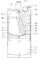
- a lower silo part 1 which is designed with a base 2 and cylindrical wall 3 as a storage silo, there is the silo part 4 according to the invention with cylindrical walls 5 and bottom 6, which is covered with ventilation devices 7.
- the bottom 6 is slightly inclined towards the center, where there is an outlet opening 8 for emptying the mixing silo 4 into the storage silo 1.
- the outlet opening 8 is closed during normal operation.
- the material to be mixed can be fed to the mixing silo 4 through a central opening 9 in the ceiling 10, which is optionally connected to a baffle plate 11 for better distribution.
- a filter 12 with a suction fan 13 for extracting the loosening air is arranged on the silo ceiling 10. ' As can be seen from the top view of Fig.
- the ventilation means 7 of the silo floor are arranged in the form of four quadrant-shaped ventilation fields, each of which forms one of the groups mentioned above. They are each divided into a zone 14 to be strongly ventilated and a zone 15 to be ventilated less, which are separated from one another in the field at the bottom right by different hatching. Zone 14, which is to be strongly ventilated, projects from the circumference into the respective ventilation field. In the two fields shown in the lower half of the illustration, it has an approximately triangular shape, while the two upper fields show an alternative design with an approximately semicircular shape.
- the zone to be poorly ventilated surrounds the zone to be ventilated strongly on its side facing the center or the other fields.
- the ratio of the area sizes of the heavily and weakly ventilated zones is in the order of about 1: 2 to 1: 4.
- the zones 14 of each ventilation field which are to be strongly ventilated are connected via lines 16 with solenoid valves 17 and via a line 18 to a first blower 19, while the zones 15 of each field which are to be ventilated less are connected to a second blower 23 via lines 20 and 21 and solenoid valves 22 are connected.
- the blower 19 is for the air requirement in each case a zone 14 to be strongly ventilated the blower 23 is designed for a weakly ventilated zone 15.
- the solenoid valves are timed so that only zones 14, 15 of an aeration field are in operation, for a period of, for example, 5 minutes. Then they are switched so that each ventilation field is activated all around or alternately in a different order.
- each zone 14 to be strongly ventilated there is a vertical overflow pipe 24 near the silo wall 5, the inlet mouth of which is at the desired level with fluidized material.
- the overflow pipes 24 can be provided with closure members which are controlled in accordance with the change in the ventilation fields. However, this is generally not necessary because - as indicated in FIG. 2 - the fill level above the highly ventilated zone is higher than that above the other zones, so that only here the opening 25 of the overflow pipe 24 is reached while the openings of the other overflow pipes are higher. While, as indicated in FIG. 2, the material flows downwards in the overflow pipe 24 assigned to the ventilation field currently in operation, the other overflow pipes allow the counterflow of air from the storage silo 1 into the upper space of the mixing silo 4.
- the silo according to the invention can be operated continuously and still be dimensioned so large that it has the grinding capacity required to compensate for long-term compositional fluctuations Time period, for example of 8 hours, can record.
- the silo according to the invention is also low-maintenance, because on the one hand it is simple in construction and on the other hand the effort for Control and transport facilities is low.
Landscapes
- Chemical & Material Sciences (AREA)
- Chemical Kinetics & Catalysis (AREA)
- Storage Of Harvested Produce (AREA)
- Apparatuses For Bulk Treatment Of Fruits And Vegetables And Apparatuses For Preparing Feeds (AREA)
Applications Claiming Priority (2)
| Application Number | Priority Date | Filing Date | Title |
|---|---|---|---|
| DE3245542 | 1982-12-09 | ||
| DE19823245542 DE3245542A1 (de) | 1982-12-09 | 1982-12-09 | Mischsilo |
Publications (3)
| Publication Number | Publication Date |
|---|---|
| EP0111294A2 true EP0111294A2 (fr) | 1984-06-20 |
| EP0111294A3 EP0111294A3 (en) | 1985-07-03 |
| EP0111294B1 EP0111294B1 (fr) | 1987-08-12 |
Family
ID=6180198
Family Applications (1)
| Application Number | Title | Priority Date | Filing Date |
|---|---|---|---|
| EP83112262A Expired EP0111294B1 (fr) | 1982-12-09 | 1983-12-06 | Silo-mélangeur pour l'homogénéisation pneumatique de matières granuleuses et pulvérulentes |
Country Status (6)
| Country | Link |
|---|---|
| US (1) | US4542991A (fr) |
| EP (1) | EP0111294B1 (fr) |
| BR (1) | BR8306783A (fr) |
| DE (2) | DE3245542A1 (fr) |
| DK (1) | DK157835C (fr) |
| ES (1) | ES284574Y (fr) |
Cited By (1)
| Publication number | Priority date | Publication date | Assignee | Title |
|---|---|---|---|---|
| EP0199886A1 (fr) * | 1985-05-03 | 1986-11-05 | Claudius Peters Aktiengesellschaft | Silo de mélange et de stockage |
Families Citing this family (6)
| Publication number | Priority date | Publication date | Assignee | Title |
|---|---|---|---|---|
| US4834544A (en) * | 1987-07-06 | 1989-05-30 | Fuller Company | Fines separation system for pellet blender |
| US6138377A (en) * | 1999-07-21 | 2000-10-31 | United States Gypsum Company | Apparatus and process for cooling and de-steaming calcined stucco |
| GB2384161A (en) * | 2001-12-04 | 2003-07-23 | Powder Conditioning Ltd | Conditioning powders |
| DE10308722A1 (de) * | 2003-02-28 | 2004-09-09 | Degussa Ag | Homogenisierung von nanoskaligen Pulvern |
| US7275856B2 (en) * | 2004-09-30 | 2007-10-02 | Rohm And Haas Electronic Materials Cmp Holdings, Inc. | Apparatus for forming a polishing pad having a reduced striations |
| ES2311258T3 (es) * | 2006-09-08 | 2009-02-01 | Ibau Hamburg Ingenieurgesellschaft Industriebau Mbh | Metodo y sistema para el llenado de silos de gran capacidad de almacenamiento con material fluidizable. |
Family Cites Families (17)
| Publication number | Priority date | Publication date | Assignee | Title |
|---|---|---|---|---|
| DD61194A (fr) * | ||||
| DE1027966B (de) * | 1953-07-29 | 1958-04-10 | Peters Ag Claudius | Verfahren zum Mischen und Homogenisieren trockener pulveriger Stoffe auf teilweise pneumatischem Wege |
| DE1152876B (de) * | 1958-05-20 | 1963-08-14 | Fuller Co | Verfahren und Vorrichtung zum Konditionieren, insbesondere Durchmischen von pulverfoermigem Material |
| DE1138608B (de) * | 1960-09-07 | 1962-10-25 | Peters Ag Claudius | Verfahren und Einrichtung zum pneumatischen Mischen von staub-foermigem oder feinkoernigem trockenem Gut |
| FR1325873A (fr) * | 1962-03-26 | 1963-05-03 | Shell Int Research | Procédé de mélange de matières en poudre |
| DE1906018A1 (de) * | 1969-02-07 | 1970-09-03 | Peters Ag Claudius | Verfahren zum pneumatischen Mischen von staubfoermigem oder feinkoernigem Gut |
| GB1269756A (en) * | 1969-08-28 | 1972-04-06 | Polysius Ag | A method for the continuous pneumatic treatment of fine material |
| US3653639A (en) * | 1971-02-04 | 1972-04-04 | Whirl Air Flow Corp | High pressure air and liquid blending method and apparatus for discrete materials |
| DE2108418C3 (de) * | 1971-02-22 | 1975-07-03 | Polysius Ag, 4723 Neubeckum | Verfahren zum pneumatischen Mischen und Homogenisieren |
| DE2223550A1 (de) * | 1972-05-15 | 1973-12-06 | Hans-Joachim Dipl-Ing Selig | Querstromboden fuer homogenisierung rieselfaehiger schuettgueter |
| FR2261804A1 (en) * | 1974-02-26 | 1975-09-19 | Daloz Ets | Homogenising dry powders in fluidised bed mixer - with several different fluidising conditions in adjacent sectors of the bed |
| DE2436414C2 (de) * | 1974-07-29 | 1975-11-06 | Claudius Peters Ag, 2000 Hamburg | Verfahren zum Betrieb einer Vorrichtung zum Mischen von Schüttgut |
| FR2374073A1 (fr) * | 1976-12-18 | 1978-07-13 | Peters Ag Claudius | Silo a chambre de melange pour matieres en vrac |
| US4375335A (en) * | 1977-06-30 | 1983-03-01 | Klein Albenhausen Heinrich | Silo combination for mixing stored material |
| DE2949791A1 (de) * | 1979-12-11 | 1981-06-19 | Krupp Polysius Ag, 4720 Beckum | Vorrats- und mischsilo fuer schuettgut |
| DE3026472C2 (de) * | 1980-07-12 | 1983-04-21 | Claudius Peters Ag, 2000 Hamburg | Verfahren zum Betrieb eines Schüttgutsilos |
| DE3143387A1 (de) * | 1981-11-02 | 1983-05-11 | Krupp Polysius Ag, 4720 Beckum | Verfahren zum betrieb eines durchlaufmischsilos |
-
1982
- 1982-12-09 DE DE19823245542 patent/DE3245542A1/de not_active Ceased
-
1983
- 1983-12-06 EP EP83112262A patent/EP0111294B1/fr not_active Expired
- 1983-12-06 DE DE8383112262T patent/DE3372925D1/de not_active Expired
- 1983-12-07 ES ES1983284574U patent/ES284574Y/es not_active Expired
- 1983-12-08 US US06/559,421 patent/US4542991A/en not_active Expired - Fee Related
- 1983-12-08 DK DK564683A patent/DK157835C/da not_active IP Right Cessation
- 1983-12-09 BR BR8306783A patent/BR8306783A/pt unknown
Cited By (1)
| Publication number | Priority date | Publication date | Assignee | Title |
|---|---|---|---|---|
| EP0199886A1 (fr) * | 1985-05-03 | 1986-11-05 | Claudius Peters Aktiengesellschaft | Silo de mélange et de stockage |
Also Published As
| Publication number | Publication date |
|---|---|
| DE3372925D1 (en) | 1987-09-17 |
| DK157835C (da) | 1990-08-06 |
| ES284574Y (es) | 1986-04-01 |
| US4542991A (en) | 1985-09-24 |
| ES284574U (es) | 1985-07-01 |
| DK157835B (da) | 1990-02-26 |
| DK564683A (da) | 1984-06-10 |
| EP0111294A3 (en) | 1985-07-03 |
| EP0111294B1 (fr) | 1987-08-12 |
| DE3245542A1 (de) | 1984-06-14 |
| BR8306783A (pt) | 1984-07-17 |
| DK564683D0 (da) | 1983-12-08 |
Similar Documents
| Publication | Publication Date | Title |
|---|---|---|
| DE2106591A1 (de) | Mischvorrichtung fur Schuttguter | |
| DE2121616C3 (de) | Vorrichtung zum Mischen von Schüttgut und Verfahren zu Ihrem Betrieb | |
| DE2336984A1 (de) | Vorrichtung zum entleeren von silos fuer schuettgut mit flachem oder leicht geneigtem boden | |
| EP0111294B1 (fr) | Silo-mélangeur pour l'homogénéisation pneumatique de matières granuleuses et pulvérulentes | |
| DE1507888C3 (de) | Vorrichtung zum Mischen von Schüttgut mit belüftbarem Silo | |
| DE69018288T2 (de) | Vorrichtung zum Mischen und Austragen von körnigem Feststoff aus einem Behälter. | |
| EP0078396B1 (fr) | Procédé d'exploitation d'un silo de mélange de passage | |
| DE2352455B2 (de) | Großraumsilo für mehlförmige Schüttgüter | |
| DE2724928A1 (de) | Silo zur mischung von eingelagertem material | |
| EP0123031B1 (fr) | Silo pour des poudres en vrac | |
| DE3022346C2 (de) | Mischsilo für Schüttgut | |
| EP0030362B1 (fr) | Silo de stockage et de mélange pour matières en vrac | |
| DE2657597C2 (de) | Schüttgutsilo mit Homogenisierkammer | |
| DE1507901C3 (de) | Vorrichtung zum Mischen fließ fähiger teilchenförmiger Feststoffe | |
| DE3609244A1 (de) | Mischsilo fuer schuettgut | |
| DE1138608B (de) | Verfahren und Einrichtung zum pneumatischen Mischen von staub-foermigem oder feinkoernigem trockenem Gut | |
| DE4224054C2 (de) | Großraumsilo | |
| DE3727767A1 (de) | Schuettgutsilo mit pneumatischer entleerung und entluefteter auslaufkammer | |
| DE2539753B1 (de) | Mischsilo fuer schuettgut | |
| DE3040749A1 (de) | Verfahren zum mischen von schuettgut in einem mischsilo | |
| AT303625B (de) | Verfahren zum Mischen von Schüttgut in einem Mischsilo | |
| AT214243B (de) | Verfahren und Einrichtung zum pneumatischen Mischen und Homogenisieren von staubförmigem, pulverförmigem oder feinkörnigem Gut | |
| DE3926798C2 (de) | Großraumsilo | |
| DE7523514U (de) | Behälterboden zum pneumatischen Austragen von Feingut | |
| DE4034616C2 (de) | Vorrichtung zum Mischen von pulverförmigen oder grobkörnigen Schüttgütern |
Legal Events
| Date | Code | Title | Description |
|---|---|---|---|
| PUAI | Public reference made under article 153(3) epc to a published international application that has entered the european phase |
Free format text: ORIGINAL CODE: 0009012 |
|
| AK | Designated contracting states |
Designated state(s): BE DE FR GB IT |
|
| PUAL | Search report despatched |
Free format text: ORIGINAL CODE: 0009013 |
|
| AK | Designated contracting states |
Designated state(s): BE DE FR GB IT |
|
| 17P | Request for examination filed |
Effective date: 19851206 |
|
| 17Q | First examination report despatched |
Effective date: 19861007 |
|
| GRAA | (expected) grant |
Free format text: ORIGINAL CODE: 0009210 |
|
| AK | Designated contracting states |
Kind code of ref document: B1 Designated state(s): BE DE FR GB IT |
|
| REF | Corresponds to: |
Ref document number: 3372925 Country of ref document: DE Date of ref document: 19870917 |
|
| ITF | It: translation for a ep patent filed | ||
| ET | Fr: translation filed | ||
| PLBI | Opposition filed |
Free format text: ORIGINAL CODE: 0009260 |
|
| 26 | Opposition filed |
Opponent name: KRUPP POLYSIUS AG Effective date: 19880511 |
|
| PLBN | Opposition rejected |
Free format text: ORIGINAL CODE: 0009273 |
|
| STAA | Information on the status of an ep patent application or granted ep patent |
Free format text: STATUS: OPPOSITION REJECTED |
|
| 27O | Opposition rejected |
Effective date: 19890724 |
|
| ITTA | It: last paid annual fee | ||
| PGFP | Annual fee paid to national office [announced via postgrant information from national office to epo] |
Ref country code: FR Payment date: 19941215 Year of fee payment: 12 |
|
| PGFP | Annual fee paid to national office [announced via postgrant information from national office to epo] |
Ref country code: BE Payment date: 19950104 Year of fee payment: 12 |
|
| PGFP | Annual fee paid to national office [announced via postgrant information from national office to epo] |
Ref country code: GB Payment date: 19951120 Year of fee payment: 13 |
|
| PG25 | Lapsed in a contracting state [announced via postgrant information from national office to epo] |
Ref country code: BE Effective date: 19951231 |
|
| PGFP | Annual fee paid to national office [announced via postgrant information from national office to epo] |
Ref country code: DE Payment date: 19960220 Year of fee payment: 13 |
|
| BERE | Be: lapsed |
Owner name: CLAUDIUS PETERS A.G. Effective date: 19951231 |
|
| PG25 | Lapsed in a contracting state [announced via postgrant information from national office to epo] |
Ref country code: FR Effective date: 19960830 |
|
| REG | Reference to a national code |
Ref country code: FR Ref legal event code: ST |
|
| PG25 | Lapsed in a contracting state [announced via postgrant information from national office to epo] |
Ref country code: GB Effective date: 19961206 |
|
| GBPC | Gb: european patent ceased through non-payment of renewal fee |
Effective date: 19961206 |
|
| PG25 | Lapsed in a contracting state [announced via postgrant information from national office to epo] |
Ref country code: DE Effective date: 19970902 |