EP0111330A1 - Verstelleinrichtung der Leitschaufeln einer Wasserturbine - Google Patents
Verstelleinrichtung der Leitschaufeln einer Wasserturbine Download PDFInfo
- Publication number
- EP0111330A1 EP0111330A1 EP83112413A EP83112413A EP0111330A1 EP 0111330 A1 EP0111330 A1 EP 0111330A1 EP 83112413 A EP83112413 A EP 83112413A EP 83112413 A EP83112413 A EP 83112413A EP 0111330 A1 EP0111330 A1 EP 0111330A1
- Authority
- EP
- European Patent Office
- Prior art keywords
- guide
- guide ring
- operating mechanism
- guide vane
- crankshaft
- Prior art date
- Legal status (The legal status is an assumption and is not a legal conclusion. Google has not performed a legal analysis and makes no representation as to the accuracy of the status listed.)
- Granted
Links
- 230000007246 mechanism Effects 0.000 title claims abstract description 45
- XLYOFNOQVPJJNP-UHFFFAOYSA-N water Substances O XLYOFNOQVPJJNP-UHFFFAOYSA-N 0.000 title claims abstract description 12
- 230000033001 locomotion Effects 0.000 claims abstract description 14
- 230000003247 decreasing effect Effects 0.000 description 4
- 238000009434 installation Methods 0.000 description 3
- 238000012423 maintenance Methods 0.000 description 2
- 238000012986 modification Methods 0.000 description 2
- 230000004048 modification Effects 0.000 description 2
- 238000012856 packing Methods 0.000 description 2
- 230000002093 peripheral effect Effects 0.000 description 2
- 230000005540 biological transmission Effects 0.000 description 1
- 238000010276 construction Methods 0.000 description 1
- 230000003467 diminishing effect Effects 0.000 description 1
- 230000000694 effects Effects 0.000 description 1
- 239000002184 metal Substances 0.000 description 1
Images

Classifications
-
- F—MECHANICAL ENGINEERING; LIGHTING; HEATING; WEAPONS; BLASTING
- F03—MACHINES OR ENGINES FOR LIQUIDS; WIND, SPRING, OR WEIGHT MOTORS; PRODUCING MECHANICAL POWER OR A REACTIVE PROPULSIVE THRUST, NOT OTHERWISE PROVIDED FOR
- F03B—MACHINES OR ENGINES FOR LIQUIDS
- F03B3/00—Machines or engines of reaction type; Parts or details peculiar thereto
- F03B3/16—Stators
- F03B3/18—Stator blades; Guide conduits or vanes, e.g. adjustable
- F03B3/183—Adjustable vanes, e.g. wicket gates
-
- Y—GENERAL TAGGING OF NEW TECHNOLOGICAL DEVELOPMENTS; GENERAL TAGGING OF CROSS-SECTIONAL TECHNOLOGIES SPANNING OVER SEVERAL SECTIONS OF THE IPC; TECHNICAL SUBJECTS COVERED BY FORMER USPC CROSS-REFERENCE ART COLLECTIONS [XRACs] AND DIGESTS
- Y02—TECHNOLOGIES OR APPLICATIONS FOR MITIGATION OR ADAPTATION AGAINST CLIMATE CHANGE
- Y02E—REDUCTION OF GREENHOUSE GAS [GHG] EMISSIONS, RELATED TO ENERGY GENERATION, TRANSMISSION OR DISTRIBUTION
- Y02E10/00—Energy generation through renewable energy sources
- Y02E10/20—Hydro energy
Definitions
- the present invention relates to a guide vane operating mechanism for hydraulic machines and, more particularly, to a guide vane operating mechanism of the type having a guide ring adapted to be rotatingly driven by a servomotor and a linking mechanism through which the guide ring is connected to the guide vanes of the hydraulic machine.
- a plurality of guide vanes are arranged along the inner periphery of the volute casing of the turbine. These guide vanes are adapted to change the angle at which the water is directed to the runner (referred to as “angle of attack", . hereinunder) of the turbine, thereby to control the speed of the latter.
- the change in the angle of attack is effected by rotating the guide vanes around their axes by means of a guide vane operating mechanism.
- the guide vane operating mechanism has a guide ring of an outside diameter smaller than the inside diameter of the volute casing, a plurality of linking mechanisms through which the guide vanes are connected to the guide ring, and a servomotor for rotatingly driving the guide ring.
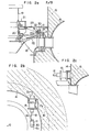
- Fig. la is a sectional view of an upper part of a Francis turbine for use in a hydraulic power generating plant
- Fig: lb is a schematic top plan view of a guide vane operating mechanism incorporated in this water turbine.
- the Francis turbine has a runner 18 integral with a main shaft 19 and adapted to be rotated by the energy of the water which is introduced from the volute casing 16 through the guide vanes 1.
- a reference numeral 20 designates a water seal packing for the main shaft 19, 21 denotes a metal case, 22 denotes an upper cover, and 23 denotes the floor of an access passage which is fixed to a pit liner 114-so as to cover a guide ring 6 which will be mentioned later.
- Each guide vane 1 is mounted by an upper and lower shafts 2 and 2a for rotation around the common axis of these shafts.
- a lever 3 is fixed to the upper shaft 2 constituting an operation shaft 2 for the guide vane 1.
- the lever 3 is pivotally connected at its end to one end of a link 5 through a pin 4.
- the other end of the link 5 is pivotally connected through a pin 7 to the lower annular flange 6a of the guide ring 6 surrounding the main shaft 19.
- the guide vanes 1 are rotated around the axes of the shafts 2, 2a through the action of the levers 3 and the links 5.
- the orientation of the guide vanes 1, i.e. the angle of attack at which the water comes into collision with the flades of the runner 18, is determined in accordance with the rotational position of the guide ring 6.
- the guide ring 6 is adapted to slide along a guide rail 61.
- Fig. lb schematically shows the servomotor device incorporated in the guide vane operating mechanism.
- This servomotor device has a link 8 having a forked end which is pivotally connected through a pin 9 to an upper annular flange 6c of the guide ring 6 in such a manner that the flange 6c is sandwiched between both fingers of the forked end.
- the other end of the link 8 which is also forked is pivotally connected through a pin 10 to a fitting 11 fitted onto the end of the piston rod 12 of a servomotor 13.
- the servomotor 13 is fixed at its rear end by bolts 13a and nuts 13b to a fixing member 15a laid on the concrete wall 15a along the pit liner 14.
- the servomotor 13 In order that the servomotor 13 can operate safely, it is essential to avoid, when the piston rod 12 is moved in the direction of the arrow, any interference between the outer extremity of the fitting 11 shown by the broken line and the upper flange 6c of the guide ring 6. To this end, it is necessary to preserve a large distance between the pins 9 and 10 on the link 8, which causes the link 8 to have a large length. This requires to shift the position of the installation of the servomotor 13 backwardly. Unfortunately, however, it is not allowed to shift the servomotor 13 unlimitedly because of the interference of the servomotor with the turbine casing 16.
- the increased height of the guide ring 6 imposes another problem that, since the guide ring 6 having such a large height conceales the main shaft 19, it becomes quite difficult to effect the maintenance work around the main shaft 19 such as renewal of the water seal packing 20 on the main shaft 19.
- an object of the invention is to reduce the dimensions of the guide vane operating mechanism by decreasing the area of the pit for installing the servomotor and diminishing the height of the guide ring.
- a guide vane operating mechanism for a hydraulic machine having a main shaft carrying a runner, and guide vanes for varying the angle of attack of the water to the runner comprising: a guide ring rotatably arranged around the main shaft; a guide vane driving mechanism for linkage between said guide vanes and said guide ring to drive said guide vanes between full-open and full-close positions; at least one servomotor having a reciprocatingly actuating rod;.and a guide ring actuating mechanism for transmitting the drive power to the guide ring so as to cause a rotation of the latter; wherein the guide ring actuating mechanism includes connecting means for connecting the actuating rod to the guide ring so as to permit the actuating rod and the guide ring to make a cranking motion relative to each other.
- the connecting means permitting the actuating rod and the guide ring to make a cranking motion relative to each other comprises a crankshaft composed of two cylindrical columns integrally connected to each other at an eccentricity from each other.
- the guide vane operating mechanism of the invention since the end of the actuating rod of the servomotor is connected to the guide ring through the crankshaft, it is possible to eliminate the elongated link which is indispensable in the conventional guide vane operating mechanism. Consequently, the servomotor can be mounted substantially at the same level as the guide ring without the fear of interference with the casing. Thus, the guide vane operating mechanism can be mounted in a compact manner within the inner periphery of the casing. In addition, the guide ring does not impede the maintenance work around the main shaft because it can be devoid of the high peripheral wall.
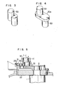
- a guide vane operating mechanism of the invention has a crankshaft 30 composed of two cylindrical columns integrally connected to each other with their axes r and 1 disposed at an eccentricity from each other.
- One end of the crankshaft 30 is rotatably received by the fitting 11 on the piston rod 12, while the other end of the same is rotatably received by the guide ring 31.
- the guide ring 31 has an annular disc-link form with its inner peripheral edge guided by the step of an inner cylinder 22a of the upper cover 22.
- a reference numeral 32 designates an eccentric pin which is composed of a pair of cylindrical columns integral with each other with their axes disposed at an eccentricity from each other as in the case of the crankshaft 30.
- the eccentric pin 32 is rotatably received at its one end by a guide ring 31 while the other end of the same rotatably fits in a bore formed in one end of one of a plurality of levers 32.
- the levers 33 which corresponds in number to the number of the guide vanes 1, are arranged at a constant circumferential pitch on the outer periphery of the guide ring 31, and the other ends of the levers 33 are connected to the upper operation shafts 2 of the corresponding guide vanes 1.
- the two cylindrical columns constituting the crankshaft 30 may be connected directly to each other or may be connected indirectly to each other through a crank web portion 30a having a width greater than the outside diameter of the columns.
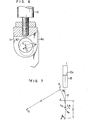
- the angle a (see Fig. 6) formed between the line of movement of the fitting 11 and the line interconnecting the centers of the cylindrical columns of the crankshaft 30 is selected to range between 0 and 45°.
- the efficiency of transmission of force from the piston rod 12 to the fitting 11 is decreased as this angle a grows large.
- the installation of the servomotor 13 requires only a small space 17a slightly projecting from the pit liner 14, so that the interference between the servomotor 13 and the casing 16 is avoided advantageously.
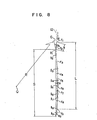
- a reference symbol Q represents the center of the guide ring
- R represents the radius of the arcuate path G of movement of the portion of the crankshaft 30 received by the guide ring 31 as measured from the center Q of the guide ring 31.
- An arc 1 1 - I 9 is the locus of movement of the axis 1 of the portion of the crankshaft 30 received by the guide ring 31 during the operation of the guide vanes between the full-open position and the full-close position.
- a symbol S represents the distance travelled by this portion of the crankshaft 30 when the same is moved from the point 1 1 to the point 1 9 .
- a line r l - r 9 is the linear locus drawn by the axis r of the portion of the crankshaft 30 received by the fitting 11.
- a symbol L represents the distance travelled by this portion of the crankshaft 30 when the same is moved from the point r 1 to the point r 9 .
- the distances S and L which are the same to each other, are equal to the distance of movement of the piston rod 12, i.e. the distance of movement of the fitting 11.
- the points r 5 and 1 5 correspond to the half opening of the guide vanes 1.
- a symbol ⁇ represents the distance or eccentricity between the axes of two cylindrical columns of the crankshaft 30.
- the operation of the guide vane operating mechanism is as follows.
- the positions r 1 and 1 1 of respective portions of the crankshaft 30 correspond to the full-open position of the guide vanes.
- the guide ring 31 is rotated around the center Q thereof along the locus G of the radius R. Consequently, the axes r and 1 of respective portions of the crankshaft 30 are started from the positions r l , 1 1 and are moved past the positions r 2 , 1 2 ; r 3' 1 3 and r 4' 1 4 to reach the positions r 5 , 1 5 corresponding to the half opening of the guide vanes.
- the axis of the position of the crankshaft represented by r makes a linear movement despite the rotation of the crankshaft 30.
- the portion of the crankshaft represented by 1 moves along the arcuate path G. More specifically, the points 1 1 , 1 2 and 1 9 are located at the left side of the axis r of the crankshaft 30 making a linear movement, while the points 1 3 to 1 7 are located at the right side of the same, thereby to smooth the linear motion of the piston rod 12.
- the piston rod 12 is reversed so that the axes r and 1 of the crankshaft 30 are moved from the positions r 9 , 1 9 to the positions r l , l 1 , respectively.
- the link which is used for actuating the guide ring in the conventional guide vane operating mechanism it is possible to eliminate the link which is used for actuating the guide ring in the conventional guide vane operating mechanism. Consequently, the area of the pit portion for the installation of the servomotor is decreased and the dimentions of the guide ring can be decreased remarkably, so that the dimentions of the guide vane operating mechanism can be reduced advantageously.
- eccentric pin 32 is used for pivotally connecting the lever 33 to the guide ring 31, this may be substituted by a link of the same type as the link 5 used in the conventional arrangement shown in Fig. la.
Landscapes
- Engineering & Computer Science (AREA)
- Chemical & Material Sciences (AREA)
- Combustion & Propulsion (AREA)
- Mechanical Engineering (AREA)
- General Engineering & Computer Science (AREA)
- Hydraulic Turbines (AREA)
Applications Claiming Priority (2)
| Application Number | Priority Date | Filing Date | Title |
|---|---|---|---|
| JP57215562A JPS59105973A (ja) | 1982-12-10 | 1982-12-10 | 水力機械の案内羽根操作装置 |
| JP215562/82 | 1982-12-10 |
Publications (2)
| Publication Number | Publication Date |
|---|---|
| EP0111330A1 true EP0111330A1 (de) | 1984-06-20 |
| EP0111330B1 EP0111330B1 (de) | 1987-09-02 |
Family
ID=16674479
Family Applications (1)
| Application Number | Title | Priority Date | Filing Date |
|---|---|---|---|
| EP83112413A Expired EP0111330B1 (de) | 1982-12-10 | 1983-12-09 | Verstelleinrichtung der Leitschaufeln einer Wasserturbine |
Country Status (5)
| Country | Link |
|---|---|
| US (1) | US4575307A (de) |
| EP (1) | EP0111330B1 (de) |
| JP (1) | JPS59105973A (de) |
| CA (1) | CA1221893A (de) |
| DE (1) | DE3373324D1 (de) |
Cited By (3)
| Publication number | Priority date | Publication date | Assignee | Title |
|---|---|---|---|---|
| RU2181442C2 (ru) * | 2000-06-08 | 2002-04-20 | Акционерное общество открытого типа "Ленинградский Металлический завод" | Статорная часть вертикальной гидромашины |
| CN109763928A (zh) * | 2017-11-09 | 2019-05-17 | 株式会社东芝 | 导流叶片以及流体机械 |
| USD956391S1 (en) | 2017-05-16 | 2022-07-05 | Nike, Inc. | Shoe |
Families Citing this family (8)
| Publication number | Priority date | Publication date | Assignee | Title |
|---|---|---|---|---|
| US4741666A (en) * | 1985-12-23 | 1988-05-03 | Ishikawajima-Harima Jukogyo Kabushiki Kaisha | Variable displacement turbocharger |
| US4955789A (en) * | 1989-04-24 | 1990-09-11 | American Hydro Corporation | Duplex turbine replacement unit and method |
| US5441384A (en) * | 1993-10-15 | 1995-08-15 | Hydro West Group, Inc. | Hydraulic turbine and guide gate apparatus and runner apparatus therefor |
| JP3798457B2 (ja) * | 1996-01-23 | 2006-07-19 | 株式会社東芝 | 水力機械 |
| CA2358722A1 (fr) * | 2001-10-11 | 2003-04-11 | Alstom Canada Inc. | Turbine hydraulique avec tourbillon centripete et distributeur axial |
| US20040101401A1 (en) * | 2002-11-25 | 2004-05-27 | Gerler Timothy David | Electromagnetic coupling device for control of hydraulic turbines |
| JP6983530B2 (ja) * | 2017-04-20 | 2021-12-17 | 株式会社東芝 | 水車のガイドベーン装置及びそのガイドベーン装置を備えた水車 |
| US12146415B2 (en) * | 2022-12-30 | 2024-11-19 | Rolls-Royce North American Technologies Inc. | Systems and methods for multi-dimensional variable vane stage rigging utilizing adjustable bracket plates |
Citations (2)
| Publication number | Priority date | Publication date | Assignee | Title |
|---|---|---|---|---|
| CH207772A (de) * | 1937-05-24 | 1939-11-30 | Voith Gmbh J M | Einrichtung an Kreiselmaschinen. |
| GB927623A (en) * | 1958-10-16 | 1963-05-29 | Escher Wyss Ag | Adjusting devices for the guide blading of water turbines |
Family Cites Families (13)
| Publication number | Priority date | Publication date | Assignee | Title |
|---|---|---|---|---|
| CA474667A (en) * | 1951-06-19 | L. Avery Clarence | Turbine gate latch mechanism | |
| US1725421A (en) * | 1921-06-07 | 1929-08-20 | I P Morris Corp | Gate-operating mechanism |
| US1706372A (en) * | 1926-06-28 | 1929-03-19 | Allis Chalmers Mfg Co | Hydraulic machine |
| US2746713A (en) * | 1950-08-04 | 1956-05-22 | Neyrpic Ets | Distributor vane operating apparatus for hydraulic turbines |
| US2904307A (en) * | 1956-10-01 | 1959-09-15 | Crane Co | Cooling turbine |
| AT215376B (de) * | 1958-10-16 | 1961-05-25 | Escher Wyss Ag | Verstelleinrichtung für den Leitapparat einer Wasserturbine |
| GB1042509A (en) * | 1962-07-31 | 1966-09-14 | English Electric Co Ltd | Improvements in or relating to hydraulic reaction turbine alternator sets |
| US3251539A (en) * | 1963-05-15 | 1966-05-17 | Westinghouse Electric Corp | Centrifugal gas compressors |
| US3452961A (en) * | 1966-05-02 | 1969-07-01 | Keystone Valve Corp | Disc valve operator with compound driving linkage |
| US3533709A (en) * | 1968-12-05 | 1970-10-13 | Baldwin Lima Hamilton Corp | Method of operating a pump-turbine in spinning reserve |
| US3901624A (en) * | 1973-12-10 | 1975-08-26 | Allis Chalmers | Integrated gate operating servomotor |
| US4210408A (en) * | 1978-10-30 | 1980-07-01 | Allis-Chalmers Corporation | Eccentric pin positive locking device for hydraulic turbine wicket gates |
| US4403913A (en) * | 1981-11-03 | 1983-09-13 | Helsingoer Vaerft A/S | Guide blade arrangement for adjustable guide blades |
-
1982
- 1982-12-10 JP JP57215562A patent/JPS59105973A/ja active Granted
-
1983
- 1983-12-08 US US06/559,268 patent/US4575307A/en not_active Expired - Fee Related
- 1983-12-09 EP EP83112413A patent/EP0111330B1/de not_active Expired
- 1983-12-09 DE DE8383112413T patent/DE3373324D1/de not_active Expired
- 1983-12-09 CA CA000442919A patent/CA1221893A/en not_active Expired
Patent Citations (2)
| Publication number | Priority date | Publication date | Assignee | Title |
|---|---|---|---|---|
| CH207772A (de) * | 1937-05-24 | 1939-11-30 | Voith Gmbh J M | Einrichtung an Kreiselmaschinen. |
| GB927623A (en) * | 1958-10-16 | 1963-05-29 | Escher Wyss Ag | Adjusting devices for the guide blading of water turbines |
Cited By (3)
| Publication number | Priority date | Publication date | Assignee | Title |
|---|---|---|---|---|
| RU2181442C2 (ru) * | 2000-06-08 | 2002-04-20 | Акционерное общество открытого типа "Ленинградский Металлический завод" | Статорная часть вертикальной гидромашины |
| USD956391S1 (en) | 2017-05-16 | 2022-07-05 | Nike, Inc. | Shoe |
| CN109763928A (zh) * | 2017-11-09 | 2019-05-17 | 株式会社东芝 | 导流叶片以及流体机械 |
Also Published As
| Publication number | Publication date |
|---|---|
| DE3373324D1 (en) | 1987-10-08 |
| CA1221893A (en) | 1987-05-19 |
| JPS59105973A (ja) | 1984-06-19 |
| EP0111330B1 (de) | 1987-09-02 |
| US4575307A (en) | 1986-03-11 |
| JPH0428906B2 (de) | 1992-05-15 |
Similar Documents
| Publication | Publication Date | Title |
|---|---|---|
| EP0111330A1 (de) | Verstelleinrichtung der Leitschaufeln einer Wasserturbine | |
| US4871923A (en) | Wind power device | |
| KR101776349B1 (ko) | 회전 운동을 병진 운동으로 전환하기 위한 장치 | |
| GB2301868A (en) | Actuator mechanism with emergency drive for variable angle vane arrays | |
| RU2496028C2 (ru) | Устройство для изменения наклона лопасти импеллера/пропеллера и вентилятор, содержащий это устройство | |
| JP2691136B2 (ja) | 風車の可変ピッチ機構 | |
| SE464367B (sv) | Ventilmekanism foer styrning av en tallriksventil | |
| KR920008187B1 (ko) | 튜뷸러수차(水車) | |
| US4534705A (en) | Horizontal-shaft wind turbine with few blades | |
| US4440034A (en) | Eccentric vibrator with shifting coupling | |
| US2281214A (en) | Turbo machine | |
| KR102911958B1 (ko) | 수평방향 편심 원을 이용한 edg 조속기 | |
| JPS6354144B2 (de) | ||
| JP3933727B2 (ja) | サーボモータの取付支持構造 | |
| JP2802500B2 (ja) | 可動翼水車のランナベーン操作機構 | |
| JPH073217B2 (ja) | チユ−ブラ水車 | |
| JPS61192859A (ja) | 円筒水車のガイドベ−ン開閉装置 | |
| US2087323A (en) | Hydraulic machine | |
| SU1585140A1 (ru) | Машина ударного действи | |
| KR100436402B1 (ko) | 스토커식 소각로의 왕복동식 화격자 운전 장치 | |
| JPS60162073A (ja) | 斜流水車用ランナベ−ン操作機構 | |
| KR0185494B1 (ko) | 중장비의 엔진회전수 변환장치 및 조립방법 | |
| JP3332406B2 (ja) | 可動翼水力機械のランナベーン操作装置 | |
| SU364759A1 (ru) | Система программного управления холостым выпуском гидротурбины | |
| JP3372293B2 (ja) | ポンプ翼の可変装置 |
Legal Events
| Date | Code | Title | Description |
|---|---|---|---|
| PUAI | Public reference made under article 153(3) epc to a published international application that has entered the european phase |
Free format text: ORIGINAL CODE: 0009012 |
|
| AK | Designated contracting states |
Designated state(s): CH DE LI |
|
| 17P | Request for examination filed |
Effective date: 19840626 |
|
| GRAA | (expected) grant |
Free format text: ORIGINAL CODE: 0009210 |
|
| AK | Designated contracting states |
Kind code of ref document: B1 Designated state(s): CH DE LI |
|
| REF | Corresponds to: |
Ref document number: 3373324 Country of ref document: DE Date of ref document: 19871008 |
|
| PLBE | No opposition filed within time limit |
Free format text: ORIGINAL CODE: 0009261 |
|
| STAA | Information on the status of an ep patent application or granted ep patent |
Free format text: STATUS: NO OPPOSITION FILED WITHIN TIME LIMIT |
|
| 26N | No opposition filed | ||
| PGFP | Annual fee paid to national office [announced via postgrant information from national office to epo] |
Ref country code: DE Payment date: 19920214 Year of fee payment: 9 |
|
| PGFP | Annual fee paid to national office [announced via postgrant information from national office to epo] |
Ref country code: CH Payment date: 19920225 Year of fee payment: 9 |
|
| PG25 | Lapsed in a contracting state [announced via postgrant information from national office to epo] |
Ref country code: LI Effective date: 19921231 Ref country code: CH Effective date: 19921231 |
|
| REG | Reference to a national code |
Ref country code: CH Ref legal event code: PL |
|
| PG25 | Lapsed in a contracting state [announced via postgrant information from national office to epo] |
Ref country code: DE Effective date: 19930901 |