EP0111468A2 - Safety seat - Google Patents
Safety seat Download PDFInfo
- Publication number
- EP0111468A2 EP0111468A2 EP83890205A EP83890205A EP0111468A2 EP 0111468 A2 EP0111468 A2 EP 0111468A2 EP 83890205 A EP83890205 A EP 83890205A EP 83890205 A EP83890205 A EP 83890205A EP 0111468 A2 EP0111468 A2 EP 0111468A2
- Authority
- EP
- European Patent Office
- Prior art keywords
- seat
- support
- rails
- safety seat
- suspension
- Prior art date
- Legal status (The legal status is an assumption and is not a legal conclusion. Google has not performed a legal analysis and makes no representation as to the accuracy of the status listed.)
- Granted
Links
Images
Classifications
-
- A—HUMAN NECESSITIES
- A47—FURNITURE; DOMESTIC ARTICLES OR APPLIANCES; COFFEE MILLS; SPICE MILLS; SUCTION CLEANERS IN GENERAL
- A47D—FURNITURE SPECIALLY ADAPTED FOR CHILDREN
- A47D1/00—Children's chairs
- A47D1/002—Children's chairs adjustable
-
- A—HUMAN NECESSITIES
- A47—FURNITURE; DOMESTIC ARTICLES OR APPLIANCES; COFFEE MILLS; SPICE MILLS; SUCTION CLEANERS IN GENERAL
- A47D—FURNITURE SPECIALLY ADAPTED FOR CHILDREN
- A47D1/00—Children's chairs
- A47D1/10—Children's chairs capable of being suspended from, or attached to, tables or other articles
Definitions
- the invention relates to a safety seat, in particular child seat comprising a Basisträ he g, of which carrier supports for the seat suspension protrude.
- the seat supports are firmly attached to the support supports, so that the seat cannot be adapted to the child using it.
- the invention has for its object to provide a seat of the type mentioned in such a way that, in addition to high stability, there is also adaptability to the size of the child using it.
- this object is achieved in that the support supports for the seat suspension are designed as parallel support rails, onto which the seat suspension can be pushed and fixed.
- a corresponding height adjustment can be achieved by simply moving the seat suspension along the mounting rails.
- the support rails can advantageously be rigidly connected to the base support, as a result of which a particularly high stability of the substructure of the seat is achieved.
- the support rails can be attached in the front area of the base support and inclined to the rear relative to the same, which provides good support and thus particularly high stability.
- the seat suspension can have sleeves that can be pushed onto the mounting rails, from which tabs extend, on which the seat support holding the seat shell is rotatably mounted and can be fixed in the selected rotational position. This allows you to adjust the seat to any desired angle, which is necessary for the child's activity.
- the seat with its base support can also be attached to a vertical part, e.g. B.
- lockable toothed lock washers can be provided, one of which is rotationally fastened to the seat support and the other to the associated bracket, whereby a particularly reliable, also violent movements of the child resisting fixing of the seat in the selected rotational position is achieved .
- the inclination of the support rails relative to the base support can preferably be approximately 45 °, as a result of which a corresponding height adjustment of the seat can be achieved in both the hanging and standing position thereof.
- locking bores can be provided in the mounting rails, into which bolts held in the sleeves can be inserted.
- the bolts can be loaded by a spring in the sense of falling into the locking bores.
- a base support which in the present case is designed as a closed rectangular frame; however, if the material is selected accordingly, it could also be open on one of the two narrow sides.
- parallel support rails 2 are rigidly attached as support supports for the seat suspension, u. The latter are welded to the base carrier 1 approximately in the front third of the longitudinal extent of the base carrier 1 and protrude to the rear at 45 ° inclined away from base support 1.
- Sleeves 3 can be pushed onto the mounting rails 2, from which tabs 4 protrude.
- pivot bearings 5 are provided, which are aligned with opposite sleeves 3 and in which the seat support 6 is rotatably mounted.
- the sleeves 3, the tabs 4, the pivot bearing 5 and the seat support 6 together form the seat suspension.
- the seat shell 7 is then attached to the seat support 6.
- toothed disks 8, 9 are provided on one of the rotary bearings, of which one toothed disk 8 is connected to the seat bracket 6 and the other toothed disk 9 with the adjacent bracket 4, and the teeth of which can be brought into engagement with one another.
- the toothed disks 8, 9 can be braced against one another by means of a screw spindle provided with a handwheel 10.
- the other of the pivot bearing 5 is formed by a bolt 1.
- the support rails have 2 locking bores 12, into which bolts 13 held in the sleeves 3 can be inserted.
- the bolts 13 are loaded by a spring 14 (FIG. 4) in the sense of falling into the locking bores 12.
- the bolts 13 are provided with handles 15.
- the base support 1 is hung by means of hooks 17 on the upper cross strut or the like. between, with its rear cross member.
- the support rails 2 thus project obliquely upwards to the front.
- the two toothed disks 8, 9 are detached from one another, so that the seat support 6 and thus the seat shell 7 attached to it can be freely pivoted.
- the seat pan 7 is then pivoted into the upright position and then the seat support 6 and thus the seat pan 7 in this position by tightening the two toothed disks by means of the screw fixed spindles.
- a table 18 can be slipped onto the part of the support rails 2 projecting beyond the sleeves 3 by means of sleeves 19 fastened to it.
- the base support 1 is set up on the floor, and the seat pan 7, as described, is placed upright and fixed. Then the height of the seat shell 7 is adjusted by moving the sleeves 3 along the support rails 2.
- the bolts 13 are pulled out of the bores 12 of the mounting rails 2 by means of the handles 15 against the force of the spring 14, after which a free displacement of the sleeves 3 along the mounting rails 2 is then made possible.
- the bolts 13 are then released and dropped into the corresponding bores 12 of the mounting rails 2 by the force of the springs 14. The seat is then ready for use.
- a belt (not shown), preferably with a Velcro fastener, can be provided.
- the belt ends can be attached to a plate attached to the back of the seat shell and provided with barbs.
Landscapes
- Seats For Vehicles (AREA)
- Special Chairs (AREA)
- Carriages For Children, Sleds, And Other Hand-Operated Vehicles (AREA)
Abstract
Die Erfindung betrifft einen Sicherheitskindersitz, der einen Basisträger (1) mit davon abstehenden Tragstützen (2) für die Sitzaufhängung aufweist. Ein solcher Sitz soll durch die Erfindung an das ihn benutzende Kind anpaßbar ausgeführt werden. Hiezu ist vorgesehen, daß die Tragstützen (2) für die Sitzaufhängung als parallele Tragschienen (2) ausgebildet sind, auf welche die Sitzaufhängung durch Hülsen (3) aufschieb- und festlegbar ist. Hiedurch wird außer einer hohen Standsicherheit noch eine Anpaßbarkeit an die Größe des Kindes erzielt, dies durch einfaches Verschieben der Sitzaufhängung an den Tragschienen (2) entlang.The invention relates to a child safety seat which has a base support (1) with supporting supports (2) projecting therefrom for the seat suspension. Such a seat is to be made adaptable to the child using it by the invention. For this purpose, it is provided that the support supports (2) for the seat suspension are designed as parallel support rails (2), onto which the seat suspension can be pushed and fixed by sleeves (3). In addition to a high level of stability, adaptability to the size of the child is achieved by simply moving the seat suspension along the mounting rails (2).
Description
Die Erfindung bezieht sich auf einen Sicherheitssitz, insbesondere Kindersitz, welcher einen Basisträger aufweist, von welchem Tragstützen für die Sitzaufhängung abstehen.The invention relates to a safety seat, in particular child seat comprising a Basisträ he g, of which carrier supports for the seat suspension protrude.
Bei bekannten Ausbildungen dieser Art sind die Sitzträger an den Tragstützen fest angebracht, so daß eine Anpaßbarkeit des Sitzes an das diesen benützende Kind nicht möglich ist.In known designs of this type, the seat supports are firmly attached to the support supports, so that the seat cannot be adapted to the child using it.
Der Erfindung liegt die Aufgabe zugrunde, einen Sitz der eingangs genannten Art so auszubilden, daß außer einer hohen Standfestigkeit auch noch eine Anpaßbarkeit an die Größe des ihn benützenden Kindes gegeben ist.The invention has for its object to provide a seat of the type mentioned in such a way that, in addition to high stability, there is also adaptability to the size of the child using it.
Erfindungsgemäß wird diese Aufgabe dadurch gelöst, daß die Tragstützen für die Sitzaufhängung als parallele Tragschienen ausgebildet sind, auf welche die Sitzaufhängung aufschieb- und festlegbar ist. Dadurch kann durch einfaches Verschieben der Sitzaufhängung entlang der Tragschienen eine entsprechende Höhenverstellung erzielt werden.According to the invention, this object is achieved in that the support supports for the seat suspension are designed as parallel support rails, onto which the seat suspension can be pushed and fixed. A corresponding height adjustment can be achieved by simply moving the seat suspension along the mounting rails.
Vorteilhafterweise können die Tragschienen mit dem Basisträger starr verbunden sein, wodurch eine besonders hohe Stabilität der Unterkonstruktion des Sitzes erreicht wird. Dabei können die Tragschienen im vorderen Bereich des Basisträgers angebracht und gegenüber demselben nach hinten geneigt sein, wodurch eine gute Abstützung und damit eine besonders hohe Standfestigkeit erzielt ist. Bei einer besonders bevorzugten Ausbildung kann die Sitzaufhängung auf die Tragschienen aufschiebbare Hülsen aufweisen, von welchen Laschen ausgehen, an denen der die Sitzschale halternde Sitzträger drehbar und in der gewählten Drehstellung festlegbar gelagert ist. Dadurch kann man den Sitz in jeder gewünschten Neigung einstellen, welche für die jeweilige Tätigkeit des Kindes erforderlich ist. Außerdem kann man dadurch den Sitz mit seinem Basisträger erforderlichenfalls auch an einem vertikalen Teil, z. B. dem Kopf- oder dem Fußteil eines Spitalbettes od. dgl. aufhängen, wodurch bei kranken Kindern das Verabreichen des Essens durch das Pflegepersonal oder die Durchführung von ärztlichen Untersuchungen wesentlich erleichtert ist. Dabei können zur Festlegung der Drehstellung des Sitzträgers gegeneinander verklemmbare Zahnscheiben vorgesehen sein, von denen eine am Sitzträger und die andere an der zugehörigen Lasche drehschlüssig befestigt ist, wodurch eine besonders zuverlässige, auch heftigeren Bewegungen des Kindes widerstehende Festlegung des Sitzes in der gewählten Drehstellung erreicht ist. Bevorzugterweise kann die Neigung der Tragschienen gegenüber dem Basisträger etwa 45° betragen, wodurch eine entsprechende Höhenanpassung des Sitzes sowohl in hängender als auch stehender Lage desselben erzielbar ist. Zur besonders einfachen und lagebeständigen Anpassung des Sitzes an die Größe des ihn benützenden Kindes können in den Tragschienen Rastbohrungen vorgesehen sein, in welche in den Hülsen gehalterte Bolzen einschiebbar sind. Dabei können bei einer besonders einfach zu handhabenden Ausbildung die Bolzen im Sinne eines Einfallens in die Rastbohrungen durch eine Feder belastet sein.The support rails can advantageously be rigidly connected to the base support, as a result of which a particularly high stability of the substructure of the seat is achieved. The support rails can be attached in the front area of the base support and inclined to the rear relative to the same, which provides good support and thus particularly high stability. In a particularly preferred embodiment, the seat suspension can have sleeves that can be pushed onto the mounting rails, from which tabs extend, on which the seat support holding the seat shell is rotatably mounted and can be fixed in the selected rotational position. This allows you to adjust the seat to any desired angle, which is necessary for the child's activity. In addition, if necessary, the seat with its base support can also be attached to a vertical part, e.g. B. the head or foot of a hospital bed or the like. Hang, whereby in sick children the administration of food by the nursing staff or the implementation of medical under searches is much easier. To lock the rotational position of the seat support, lockable toothed lock washers can be provided, one of which is rotationally fastened to the seat support and the other to the associated bracket, whereby a particularly reliable, also violent movements of the child resisting fixing of the seat in the selected rotational position is achieved . The inclination of the support rails relative to the base support can preferably be approximately 45 °, as a result of which a corresponding height adjustment of the seat can be achieved in both the hanging and standing position thereof. For particularly simple and positionally stable adjustment of the seat to the size of the child using it, locking bores can be provided in the mounting rails, into which bolts held in the sleeves can be inserted. In the case of a particularly easy-to-use design, the bolts can be loaded by a spring in the sense of falling into the locking bores.
In der Zeichnung ist ein Ausführungsbeispiel des Erfindungsgegenstandes dargestellt.In the drawing, an embodiment of the subject of the invention is shown.
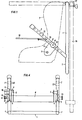
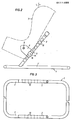
- Fig. 1 zeigt eine Seitenansicht des an einem Kopfteil eines Bettes aufgehängten Sitzes.Fig. 1 shows a side view of the seat suspended from a headboard of a bed.
- Fig. 2 ist eine Seitenansicht des am Boden aufgestellten Sitzes.Fig. 2 is a side view of the seat placed on the floor.
- Fig. 3 veranschaulicht eine Draufsicht auf den tragenden Unterteil des Sitzes.Fig. 3 illustrates a top view of the supporting lower part of the seat.
- Fig. 4 ist eine Vorderansicht des am Boden aufgestellten Sitzes bei abgenommener Sitzschale.Fig. 4 is a front view of the seat placed on the floor with the seat shell removed.
Mit 1 ist ein Basisträger bezeichnet, welcher vorliegend als geschlossener rechteckiger Rahmen ausgebildet ist; er könnte jedoch, bei entsprechend ausgewähltem Material, auch an einer der beiden Schmalseiten offen sein. An den Längsholmen 1' des Basisträgers 1 sind als Tragstützen für die Sitzaufhängung parallel verlaufende Tragschienen 2 starr befestigt, u. zw. sind letztere etwa im vorderen Drittel der Längserstreckung des Basisträgers 1 an letzterem angeschweißt und ragen unter 45° nach hinten geneigt vom Basisträger 1 weg. Auf die Tragschienen 2 sind Hülsen 3 aufschiebbar, von welchen Laschen 4 wegragen. In diesen Laschen 4 sind Drehlager 5 vorgesehen, welche bei gegenüberliegenden Hülsen 3 fluchten und in welchen der Sitzträger 6 drehbar gelagert ist. Die Hülsen 3, die Laschen 4, die Drehlager 5 und der Sitzträger 6 bilden zusammen die Sitzaufhängung. An dem Sitzträger 6 ist dann die Sitzschale 7 befestigt.1 designates a base support, which in the present case is designed as a closed rectangular frame; however, if the material is selected accordingly, it could also be open on one of the two narrow sides. On the longitudinal spars 1 'of the
Zur Festlegung einer gewählten Drehstellung zwischen dem Sitzträger 6 und den Laschen 4 sind an einem der Drehlager 5 Zahnscheiben 8, 9 vorgesehen, von denen die eine Zahnscheibe 8 mit dem Sitzträger 6 und die andere Zahnscheibe 9 mit der benachbarten Lasche 4 drehschlüssig verbunden ist, und deren Zahnungen miteinander in Eingriff bringbar sind. Dazu sind die Zahnscheiben 8, 9 mittels einer mit einem Handrad 10 versehenen Schraubspindel gegeneinander verspannbar. Das andere der Drehlager 5 ist durch einen Bolzen 1 gebildet.To determine a selected rotational position between the
Zur höhenmäßigen Verstellung des Sitzes weisen die Tragschienen 2 Rastbohrungen 12 auf, in welche in den Hülsen 3 gehalterte Bolzen 13 einschiebbar sind. Die Bolzen 13 sind dabei durch eine Feder 14 (Fig. 4) im Sinne des Einfallens in die Rastbohrungen 12 belastet. An ihren außenliegenden Enden sind die Bolzen 13 mit Handhaben 15 versehen.To adjust the height of the seat, the support rails have 2
Zur Aufhängung des Sitzes an einem der Betthäupter 16 wird der Basisträger 1 mittels Haken 17 an der oberen Querstrebe od. dgl. des.Betthauptes 16 aufgehängt, u. zw., mit seinem hinteren Querholm. Die Tragschienen 2 ragen damit schräg aufwärts nach vorne. Nun werden durch Drehen des Handrades 10, und damit der zugehörigen Schraubspindel, die beiden Zahnscheiben 8, 9 voneinander gelöst, so daß der Sitzträger 6 und damit die an diesem befestigte Sitzschale 7 frei verschwenkbar ist. Es wird dann die Sitzschale 7 in die aufrechte Stellung verschwenkt und dann der Sitzträger 6 und damit die Sitzschale 7 in dieser Stellung durch Zusammenspannen der beiden Zahnscheiben mittels der Schraubenspindeln festgelegt. Auf den über die Hülsen 3 vorstehenden Teil der Tragschienen 2 kann noch ein Tisch 18 mittels an ihm befestigter Hülsen 19 aufgesteckt werden.To hang the seat on one of the
Soll der erfindungsgemäße Sitz am Boden verwendet werden, dann wird, wie in Fig. 2 dargestellt, der Basisträger 1 am Boden aufgestellt, und die Sitzschale 7, wie beschrieben, aufrecht gestellt und festgelegt. Dann wird die Höhenlage der Sitzschale 7 durch Verschieben der Hülsen 3 entlang der Tragschienen 2 eingestellt. Dazu werden die Bolzen 13 mittels der Handhaben 15 gegen die Kraft der Feder 14 aus den Bohrungen 12 der Tragschienen 2 herausgezogen, wonach dann ein freies Verschieben der Hülsen 3 entlang der Tragschienen 2 ermöglicht ist. In der gewünschten Höhenlage der Sitzschale 7 werden dann die Bolzen 13 freigegeben und in die entsprechenden Bohrungen 12 der Tragschienen 2 durch die Kraft der Federn 14 einfallen gelassen. Danach ist der Sitz benützungsbereit.If the seat according to the invention is to be used on the floor, then, as shown in FIG. 2, the
Um ein Herausfallen des Kindes aus dem Sitz zu verhindern, kann ein nicht dargestellter Gurt, bevorzugt mit Klettenverschluß, vorgesehen sein. Die Gurtenden können dabei an einer an der Rückseite der Sitzschale befestigten, mit Widerhäkchen versehenen Platte festgelegt werden.In order to prevent the child from falling out of the seat, a belt (not shown), preferably with a Velcro fastener, can be provided. The belt ends can be attached to a plate attached to the back of the seat shell and provided with barbs.
Claims (7)
Applications Claiming Priority (2)
| Application Number | Priority Date | Filing Date | Title |
|---|---|---|---|
| AT0412682A AT388859B (en) | 1982-11-12 | 1982-11-12 | SECURITY SEAT |
| AT4126/82 | 1982-11-12 |
Publications (3)
| Publication Number | Publication Date |
|---|---|
| EP0111468A2 true EP0111468A2 (en) | 1984-06-20 |
| EP0111468A3 EP0111468A3 (en) | 1985-05-29 |
| EP0111468B1 EP0111468B1 (en) | 1988-01-20 |
Family
ID=3559999
Family Applications (1)
| Application Number | Title | Priority Date | Filing Date |
|---|---|---|---|
| EP83890205A Expired EP0111468B1 (en) | 1982-11-12 | 1983-11-11 | Safety seat |
Country Status (9)
| Country | Link |
|---|---|
| US (1) | US4615560A (en) |
| EP (1) | EP0111468B1 (en) |
| JP (1) | JPS59156838A (en) |
| AT (1) | AT388859B (en) |
| AU (1) | AU562581B2 (en) |
| CA (1) | CA1225320A (en) |
| DE (1) | DE3375368D1 (en) |
| FI (1) | FI78606C (en) |
| SU (1) | SU1340571A3 (en) |
Cited By (2)
| Publication number | Priority date | Publication date | Assignee | Title |
|---|---|---|---|---|
| FR2584908A1 (en) * | 1985-07-19 | 1987-01-23 | Aprica Kassai Kk | RAISED CHAIR |
| FR2591458A1 (en) * | 1985-08-02 | 1987-06-19 | Quaker Oats Co | BABY SEAT COULD BE USED IN COMBINATION WITH FRAME AND MOTOR TO FORM A MOTOR-DRIVEN SWEEPER |
Families Citing this family (12)
| Publication number | Priority date | Publication date | Assignee | Title |
|---|---|---|---|---|
| DE4125959C1 (en) * | 1991-08-06 | 1992-10-15 | Deutsche Airbus Gmbh, 2000 Hamburg, De | |
| JP2595597Y2 (en) * | 1992-07-23 | 1999-05-31 | 高島屋日発工業株式会社 | Vehicle seat |
| US5772279A (en) * | 1995-08-31 | 1998-06-30 | Kolcraft Enterprises, Inc. | Coupling system for infant carrier to second support device |
| US5884967A (en) * | 1997-04-17 | 1999-03-23 | Gasper; Ronald | Child vehicle safety seat |
| DE19937231C2 (en) * | 1999-08-06 | 2001-07-12 | Lufthansa Technik Ag | Airplane child seat |
| US6594840B2 (en) | 2000-06-28 | 2003-07-22 | Cosco Management, Inc. | Baby bouncer/bassinet |
| US7597396B2 (en) * | 2004-04-30 | 2009-10-06 | Chicco Usa, Inc. | Infant travel system |
| US7371335B2 (en) | 2004-10-21 | 2008-05-13 | E.I. Dupont De Nemours And Company | Curable thick film compositions for use in moisture control |
| US7651168B2 (en) * | 2006-03-03 | 2010-01-26 | Mattel, Inc. | Adjustable child support device |
| US8556344B2 (en) * | 2010-07-15 | 2013-10-15 | Wonderland Nurserygoods Company Limited | Child safety seat assembly |
| PL2865562T3 (en) | 2013-10-23 | 2019-01-31 | Wonderland Switzerland Ag | Child safety seat |
| JP7124813B2 (en) * | 2019-10-04 | 2022-08-24 | トヨタ自動車株式会社 | Child Seat Temporary Placement Structure for Passenger Vehicles |
Family Cites Families (19)
| Publication number | Priority date | Publication date | Assignee | Title |
|---|---|---|---|---|
| US2292414A (en) * | 1941-01-28 | 1942-08-11 | Forest C Vernon | Upholstered adjustable chair |
| US2599610A (en) * | 1945-07-24 | 1952-06-10 | Clairmonte Edward Hugh | Baby chair |
| US2435733A (en) * | 1946-06-10 | 1948-02-10 | Belyeu Henry | Supplemental motor vehicle seat |
| US2792054A (en) * | 1953-07-13 | 1957-05-14 | Muoio Richard | Child's auxiliary seat |
| US2805076A (en) * | 1954-06-21 | 1957-09-03 | Garrett J Thomas | Child's combination stroller, car seat, bed and highchair |
| US3116069A (en) * | 1962-03-19 | 1963-12-31 | Joseph B Dostal | Combination car seat and stroller |
| DE1817993A1 (en) * | 1968-01-12 | 1976-09-09 | Perego Giuseppe | HEIGHT-ADJUSTABLE ARMCHAIR ON A BASE FRAME |
| US3550998A (en) * | 1968-09-03 | 1970-12-29 | Hedstrom Union Co | Foldable carriage and infant seat combination |
| FR2029943A5 (en) * | 1969-01-31 | 1970-10-23 | Jankiry | |
| US3645548A (en) * | 1969-07-28 | 1972-02-29 | Arthur N Briner | Safety auto seat |
| US3625563A (en) * | 1970-05-22 | 1971-12-07 | Us Army | Tank commander{40 s seat and foot platform assembly |
| JPS4862112U (en) * | 1971-11-15 | 1973-08-07 | ||
| DK505574A (en) * | 1974-09-25 | 1976-03-26 | K Nielsen | CHILD CHAIR |
| FR2322570A1 (en) * | 1975-09-05 | 1977-04-01 | Hernandez Ramon | Inclination mechanism for baby's chair - has lockable slides on back of hinged chair shell with pivoting traversing rails |
| JPS5327170U (en) * | 1976-08-03 | 1978-03-08 | ||
| JPS542828U (en) * | 1977-06-09 | 1979-01-10 | ||
| GB1604916A (en) * | 1978-02-10 | 1981-12-16 | Inventec Licensing Bv | Seats for children |
| GR75106B (en) * | 1980-10-10 | 1984-07-13 | Maclaren Ltd Andrews | |
| DE3101605A1 (en) * | 1981-01-20 | 1982-08-26 | Benjamin Products B.V., 4879 Etten-Leur | ADJUSTABLE CHILDREN'S CHAIR |
-
1982
- 1982-11-12 AT AT0412682A patent/AT388859B/en not_active IP Right Cessation
-
1983
- 1983-11-09 CA CA000440857A patent/CA1225320A/en not_active Expired
- 1983-11-10 US US06/550,865 patent/US4615560A/en not_active Expired - Fee Related
- 1983-11-11 AU AU21171/83A patent/AU562581B2/en not_active Ceased
- 1983-11-11 EP EP83890205A patent/EP0111468B1/en not_active Expired
- 1983-11-11 JP JP58211090A patent/JPS59156838A/en active Granted
- 1983-11-11 DE DE8383890205T patent/DE3375368D1/en not_active Expired
- 1983-11-11 SU SU833664136A patent/SU1340571A3/en active
- 1983-11-11 FI FI834144A patent/FI78606C/en not_active IP Right Cessation
Cited By (5)
| Publication number | Priority date | Publication date | Assignee | Title |
|---|---|---|---|---|
| FR2584908A1 (en) * | 1985-07-19 | 1987-01-23 | Aprica Kassai Kk | RAISED CHAIR |
| GB2177907A (en) * | 1985-07-19 | 1987-02-04 | Aprica Kassai Kk | Child's high chair |
| GB2177907B (en) * | 1985-07-19 | 1989-08-02 | Aprica Kassai Kk | Childs chair |
| US4958885A (en) * | 1985-07-19 | 1990-09-25 | Aprica Kassai Kabushikikaisha | High chair |
| FR2591458A1 (en) * | 1985-08-02 | 1987-06-19 | Quaker Oats Co | BABY SEAT COULD BE USED IN COMBINATION WITH FRAME AND MOTOR TO FORM A MOTOR-DRIVEN SWEEPER |
Also Published As
| Publication number | Publication date |
|---|---|
| FI78606C (en) | 1989-09-11 |
| CA1225320A (en) | 1987-08-11 |
| FI78606B (en) | 1989-05-31 |
| US4615560A (en) | 1986-10-07 |
| JPS59156838A (en) | 1984-09-06 |
| FI834144A0 (en) | 1983-11-11 |
| DE3375368D1 (en) | 1988-02-25 |
| AU2117183A (en) | 1984-05-17 |
| FI834144L (en) | 1984-05-13 |
| AT388859B (en) | 1989-09-11 |
| SU1340571A3 (en) | 1987-09-23 |
| AU562581B2 (en) | 1987-06-11 |
| EP0111468A3 (en) | 1985-05-29 |
| JPH0120091B2 (en) | 1989-04-14 |
| ATA412682A (en) | 1989-02-15 |
| EP0111468B1 (en) | 1988-01-20 |
Similar Documents
| Publication | Publication Date | Title |
|---|---|---|
| DE69220491T2 (en) | BED WITH SEVERAL POSITIONS | |
| DE1930886B2 (en) | Device for handling weakened patients or the physically handicapped | |
| EP0111468B1 (en) | Safety seat | |
| DE69723628T2 (en) | Device for transferring a person from one seating surface to another | |
| DE3126927A1 (en) | NETBED | |
| DE68917454T2 (en) | A treatment bank. | |
| DE1816926B2 (en) | Transport and treatment couch of adjustable height - has patient support surface spaced from frame to permit insertion of X=ray cassettes | |
| DE3344372A1 (en) | Crutch mounting device | |
| DE2034099C3 (en) | Combination trolley for toddlers and their toys | |
| LU500476B1 (en) | Jumping play chair for toddler leg strength training | |
| DE3011208A1 (en) | MOTION DEVICE FOR PHYSICAL AUTHORIZATION AND THE LIKE | |
| DE202023101809U1 (en) | Sitting and standing furniture to support the movement of a person with hypotonia, ataxia and/or spastic cerebral palsy | |
| DE1079292B (en) | Holding and carrying device for travel items | |
| DE1145322B (en) | Bed place, especially hospital bed place | |
| DE2019269A1 (en) | bed | |
| AT135209B (en) | Mobile children's play chair. | |
| DE1434488C (en) | Scaffolding made of vertically stackable scaffolding posts and horizontally arranged longitudinal and transverse pegs | |
| DE202021002727U1 (en) | Medical mobile bed canopy to contain overstimulation in people with dementia and other affected people for beds, wheelchairs and couches | |
| AT393606B (en) | Wall bed | |
| DE7532217U (en) | CONVERTIBLE CHILDREN'S HIGH CHAIR | |
| DE1942238U (en) | CHILDREN'S COT. | |
| AT389224B (en) | Wheelchair | |
| DE1541324C3 (en) | Leg support for a wheelchair | |
| DE7335867U (en) | Sick bed with a removable headboard on the tunnel | |
| DE8804686U1 (en) | Detachable bassinet cradle |
Legal Events
| Date | Code | Title | Description |
|---|---|---|---|
| PUAI | Public reference made under article 153(3) epc to a published international application that has entered the european phase |
Free format text: ORIGINAL CODE: 0009012 |
|
| AK | Designated contracting states |
Designated state(s): CH DE FR GB IT LI |
|
| PUAL | Search report despatched |
Free format text: ORIGINAL CODE: 0009013 |
|
| AK | Designated contracting states |
Designated state(s): CH DE FR GB IT LI |
|
| 17P | Request for examination filed |
Effective date: 19851112 |
|
| 17Q | First examination report despatched |
Effective date: 19861001 |
|
| GRAA | (expected) grant |
Free format text: ORIGINAL CODE: 0009210 |
|
| AK | Designated contracting states |
Kind code of ref document: B1 Designated state(s): CH DE FR GB IT LI |
|
| REF | Corresponds to: |
Ref document number: 3375368 Country of ref document: DE Date of ref document: 19880225 |
|
| ITF | It: translation for a ep patent filed | ||
| GBT | Gb: translation of ep patent filed (gb section 77(6)(a)/1977) | ||
| ET | Fr: translation filed | ||
| PLBE | No opposition filed within time limit |
Free format text: ORIGINAL CODE: 0009261 |
|
| STAA | Information on the status of an ep patent application or granted ep patent |
Free format text: STATUS: NO OPPOSITION FILED WITHIN TIME LIMIT |
|
| 26N | No opposition filed | ||
| PGFP | Annual fee paid to national office [announced via postgrant information from national office to epo] |
Ref country code: GB Payment date: 19901109 Year of fee payment: 8 Ref country code: FR Payment date: 19901109 Year of fee payment: 8 |
|
| ITTA | It: last paid annual fee | ||
| PG25 | Lapsed in a contracting state [announced via postgrant information from national office to epo] |
Ref country code: GB Effective date: 19911111 |
|
| GBPC | Gb: european patent ceased through non-payment of renewal fee | ||
| PG25 | Lapsed in a contracting state [announced via postgrant information from national office to epo] |
Ref country code: FR Effective date: 19920731 |
|
| REG | Reference to a national code |
Ref country code: FR Ref legal event code: ST |
|
| PGFP | Annual fee paid to national office [announced via postgrant information from national office to epo] |
Ref country code: CH Payment date: 19921217 Year of fee payment: 10 |
|
| PGFP | Annual fee paid to national office [announced via postgrant information from national office to epo] |
Ref country code: DE Payment date: 19930111 Year of fee payment: 10 |
|
| PG25 | Lapsed in a contracting state [announced via postgrant information from national office to epo] |
Ref country code: LI Effective date: 19931130 Ref country code: CH Effective date: 19931130 |
|
| REG | Reference to a national code |
Ref country code: CH Ref legal event code: PL |
|
| PG25 | Lapsed in a contracting state [announced via postgrant information from national office to epo] |
Ref country code: DE Effective date: 19940802 |