EP0111573A1 - Système générateur d'hydrogène - Google Patents
Système générateur d'hydrogène Download PDFInfo
- Publication number
- EP0111573A1 EP0111573A1 EP82111594A EP82111594A EP0111573A1 EP 0111573 A1 EP0111573 A1 EP 0111573A1 EP 82111594 A EP82111594 A EP 82111594A EP 82111594 A EP82111594 A EP 82111594A EP 0111573 A1 EP0111573 A1 EP 0111573A1
- Authority
- EP
- European Patent Office
- Prior art keywords
- plates
- water
- hydrogen
- set forth
- oxydizing
- Prior art date
- Legal status (The legal status is an assumption and is not a legal conclusion. Google has not performed a legal analysis and makes no representation as to the accuracy of the status listed.)
- Ceased
Links
Images






Classifications
-
- C—CHEMISTRY; METALLURGY
- C01—INORGANIC CHEMISTRY
- C01B—NON-METALLIC ELEMENTS; COMPOUNDS THEREOF; METALLOIDS OR COMPOUNDS THEREOF NOT COVERED BY SUBCLASS C01C
- C01B3/00—Hydrogen; Gaseous mixtures containing hydrogen; Separation of hydrogen from mixtures containing it; Purification of hydrogen; Reversible storage of hydrogen
- C01B3/02—Production of hydrogen; Production of gaseous mixtures containing hydrogen
- C01B3/04—Production of hydrogen; Production of gaseous mixtures containing hydrogen by decomposition of inorganic compounds
- C01B3/042—Decomposition of water
-
- C—CHEMISTRY; METALLURGY
- C25—ELECTROLYTIC OR ELECTROPHORETIC PROCESSES; APPARATUS THEREFOR
- C25B—ELECTROLYTIC OR ELECTROPHORETIC PROCESSES FOR THE PRODUCTION OF COMPOUNDS OR NON-METALS; APPARATUS THEREFOR
- C25B1/00—Electrolytic production of inorganic compounds or non-metals
- C25B1/01—Products
- C25B1/02—Hydrogen or oxygen
- C25B1/04—Hydrogen or oxygen by electrolysis of water
-
- Y—GENERAL TAGGING OF NEW TECHNOLOGICAL DEVELOPMENTS; GENERAL TAGGING OF CROSS-SECTIONAL TECHNOLOGIES SPANNING OVER SEVERAL SECTIONS OF THE IPC; TECHNICAL SUBJECTS COVERED BY FORMER USPC CROSS-REFERENCE ART COLLECTIONS [XRACs] AND DIGESTS
- Y02—TECHNOLOGIES OR APPLICATIONS FOR MITIGATION OR ADAPTATION AGAINST CLIMATE CHANGE
- Y02E—REDUCTION OF GREENHOUSE GAS [GHG] EMISSIONS, RELATED TO ENERGY GENERATION, TRANSMISSION OR DISTRIBUTION
- Y02E60/00—Enabling technologies; Technologies with a potential or indirect contribution to GHG emissions mitigation
- Y02E60/30—Hydrogen technology
- Y02E60/36—Hydrogen production from non-carbon containing sources, e.g. by water electrolysis
Definitions
- the apparatus comprises constructional configurations and there is disclosed alternative embodiments for segregating the generated hydrogen gas from the oxygen gas.
- the water need not be pure and may contain contaminents. The release of the hydrogen and oxygen atoms causes the contaminents to fall away, thereby enabling the system to be utilized in a liquid slurry removal system. Alternatively, the recombining of the hydrogen and oxygen would give pure water.
- the most commonly understood method of separating the hydrogen and oxygen atoms from water is electrolysis. This comprises placing a direct current voltage in a solution of water and potasium hydroxide, When current flows, an exchange of ions and electrons occurs between the electrodes. Hydrogen atoms collect at the negative electrode (cathode) and oxygen atoms at the positive electrode (anode). A separation between the electrodes separates the gases.
- Another process under study comprises nuclear energy to supply heat in a thermal of the hydrogen dissociation.
- the problems with the process include the lack of container materials that can withstand temperatures of(3,700 degrees F) and a practical method of attaining such temperatures.
- the addition of inorganic compounds to the water permits lower temperatures but again, adds to the complexity of the process.
- a commercial method known as the Bosch process consists in passing steam over highly heated carbon in the presence of a suitable catalyst. Carbon monoxide, CO, and hydrogen are first formed as shown in the following equation:
- the carbon dioxide is separated from the hydrogen by passing the mixture through water under pressure; the carbon dioxide dissolves in the water and leaves the hydrogen pure or nearly so.
- Hydrogen is also obtained as a by-product from processes designed to prepare other substances, for example, in the preparation of chlorine by electrolysis of sodium chloride solution:
- the process of the present invention is a simple, efficient, and low cost process for separating the hydrogen and oxygen atoms from water. No chemicals are added to the water and the electrical power utilized is only negligible.
- the water (may be pure, salt water, or contaminated water) is passed between two plates of similar non-oxidizing metal.
- the one plate has placed thereon a positive potential and the other a negative potential from a very low direct voltage current power source.
- the hydrogen atoms are separated and collected for utilization.
- the contaminants in the water is forced also to dissociate itself and may be collected or utilized and disposed of. This in turn lends the process to recombining the hydrogen and oxygen into pure water.
- the direct current voltage is non-regulated and non-filtered.
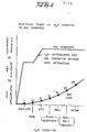
- the direct current voltage acts as a static force on the water molecules; whereas the rippling direct current voltage acts as a dynamic force. Pulsating the direct current further acts as a dynamic force and enhances considerably the splitting of the atoms from the water molecules.
- the apparatus for carrying out the process is extremely simple and can be manufactured most inexpensively. Certain plate arrangements and configurations are disclosed with graphical illustration of relative efficiency. Alternative structure for separating and collecting the hydrogen from the oxygen is disclosed.
- Another object of the present invention is to provide such a hydrogen/oxygen generator that is operable from every low electrical power, extremely efficient, and wherein the cost of operation ia most minimal.
- Another object'of the present invention is to provide a hydrogen/oxygen generator from water containing contaminents, and thereafter recombining the hydrogen/oxygen to form pure water.
- Still another object of the present invention is to provide a hydrogen/oxygen generator that utilized apparatus of simple and low cost materials, and which structure can be made in varying sizes, and duplicated without loss of efficiency.
- a structure 110 contains a water supply 15 comprising molecules 62a xxx 62n, of hydrogen 38a xxx 38n, oxygen, 39a xxx 39n, and foreign substances 64a xxx 64n.
- Attached to terminal 32 on the first of the plates 9a is a wire having its other end connected to the negative terminal there is connected another wire having its other end connected to the positive terminal of the aforesaid direct current voltage electrical source 30.
- the direct current voltage applied to the water passing between plates 9a and 9b is sufficient to dissociate the hydrogen atom 39a x x x 39n and oxygen atoms 38a x x x 39n (appearing as bubbles) from the water molecules 62a xxx 62n.
- the forceful action of the applied potential attacks the molecule structure of the water and not its atomic structure, i.e., sub-atomic.
- the foreign substance or contaminents 64a xxx 64n is broken away from the water molecule 62a xxx 62n, and spills over the outside area of the plates 9a and 9b to a collector at the bottom of the tank 110.
- the hydrogen gas 63a xxx 63n and oxygen gas 65a xxx 65n rises above the liquid.
- the gasses are separated, collected and thereafter utilized all as set forth below.
- the voltage source 30 (shown schematically in Figure 5) supplies a direct current voltage that is rectified bur-not filtered and not regulated. That is, the direct current voltage is rippled and unregulated.
- the varying amplitude peeks., ripples, in terms of applied force acts as a constant static physical force.
- the amount of electrical power required by the hydrogen/ oxygen generator of the preferred embodiment, as illustrated, is surprisingly minimal.
- the source 30 supplied 12 volts at 1 ampere to terminal 4.
- the first is to alter the plate source direct current.voltage waveform.
- FIG. 5 With particular reference to Figure 5 there is illustrated an electronic switch for switching on and off the rippled d.c output of supply 30.
- the ripple is not removed.
- the plates 32a x x x 32n are connected to a common ground 34.
- the positive terminals 33a x x x 33n are connected respectively to contacts 31a x x x 31n of switch 35 rotatively making and breaking contact with the direct-current voltage source 30.
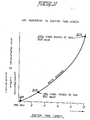
- Other structured factors altering, affecting, and particularly enhancing the hydrogen gas generating comprises altering (1) plate size, (2) plate spacing, (3) number of plates, and (4) the plate configuration. Each of these factors have been taken into consideration in the development of a plate configuration to provide optimum results for a preferred embodiment.
- each tubular plate is intended to convey a large area electrical surface; and whether the surface is flat, curved, tubular or otherwise, is of no consequence except as hereinafter defined.
- each tubular plate comprises an outside tube 32a x x x 32n, and an inside tube 33a x x x 33n.
- Connecting each of the center tubes 33a x x x 33n is a terminal wire 34; and connecting each of the outside tubes the through a common ground is a terminal wire-36.
- the two terminal wire 34 and 36 are connected to the positive and negative side respectively of the direct current voltage source 30.
- Intermediate the outside and inside tubes are a series of spacers 35a x x'x 35n.
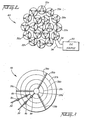
- the coaxial tubes in an array are shown pictorially in the perspective view of Figure 7 .
- This concentric ring array comprises a series of tubes each being co-axial with the other and of a size equally larger than its inner adjacent tube.
- the center tube 38a and the alternate tubes 38b and 38c serve as the positive plates connected to positive wire terminal 36.
- Each of the tubular plates 38a, 38b, and 38c are interconnected via connectors 8a and 8d to wire terminal 34.
- the three spacers .39a, 39b, and 39c maintain a uniform spacing between the respective tubular plates.
- FIG. 4 With particular reference to Figure 4 there is shown still another plate arrangement and configuration.
- the positive plates 9a x x x 9n are interconnected by electrode 12a whereas the negative plates lla x x x lln are interconnected by the electrode 12b.
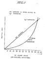
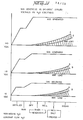
- FIG. 13 there is illustrated graphically plate spacing versus gas generation. As can be seen the greater the spacing the les.s gas generation. The efficiency versus spacing of the plates is a linear decrease with spacing.
- the applied direct current voltage across' the positive current voltage plates having water therebetween is a force applied -- in the.nature of a physical force -- to the water molecules.
- the applied force is sufficient-to cause the hydrogen and oxygen atoms to dissociate themselves from the water molecule and anything else that may be included therewith.
- the container 10 is a square elongated box configuration completely enclosing and sealing the components.as hereinafter described.
- the water is pumped or enters under normal pressure from a source via line 56.
- the water need not be pure and hence may originate from any source.
- the water from source 42 enters chamber 36 which is a free area to an open top enclosure 37.
- the water entering chamber 36 is caused to rise upwardly through the plates of the Cluster.60 previously described in more detail relative to Figure 2.
- Applied to the inner tubular structures is a positive direct current voltage, and to the outer tubular structures of the cluster array 60 is applied a negative direct current voltage.
- the direct current voltage is applied via terminals 4 connected to a suitable direct current voltage power source 30.
- the hydrogen gas is depicted in Figure 1 as a solid circle 38, whereas the oxygen gas is depicted as the open circles 39.
- the separated hydrogen and oxygen gas rises into the accumulator chamber 47.
- the intake water will include several forms of contaminents.
- the contaminents adhering to the water molecules are shaken loose and released therefrom.
- the contaminents rise to the top of chamber 37 and form a part of the spillway 41.
- the containments do not contain hydrogen or oxygen, there will be no atomic breakup.
- the combination of water with contaminents drops down into ex- traction chamber 43.
- the water cleansed of substantially all contaminents exits via pipe 45 and then through line 55 and back to inlet pipe 42.
- the combined water from inlets 55 and 56 is again processed as aforesaid.
Landscapes
- Chemical & Material Sciences (AREA)
- Organic Chemistry (AREA)
- Inorganic Chemistry (AREA)
- Engineering & Computer Science (AREA)
- Chemical Kinetics & Catalysis (AREA)
- Electrochemistry (AREA)
- Materials Engineering (AREA)
- Metallurgy (AREA)
- Health & Medical Sciences (AREA)
- General Health & Medical Sciences (AREA)
- Combustion & Propulsion (AREA)
- Electrolytic Production Of Non-Metals, Compounds, Apparatuses Therefor (AREA)
Priority Applications (1)
| Application Number | Priority Date | Filing Date | Title |
|---|---|---|---|
| EP82111594A EP0111573A1 (fr) | 1982-12-14 | 1982-12-14 | Système générateur d'hydrogène |
Applications Claiming Priority (1)
| Application Number | Priority Date | Filing Date | Title |
|---|---|---|---|
| EP82111594A EP0111573A1 (fr) | 1982-12-14 | 1982-12-14 | Système générateur d'hydrogène |
Publications (1)
| Publication Number | Publication Date |
|---|---|
| EP0111573A1 true EP0111573A1 (fr) | 1984-06-27 |
Family
ID=8189400
Family Applications (1)
| Application Number | Title | Priority Date | Filing Date |
|---|---|---|---|
| EP82111594A Ceased EP0111573A1 (fr) | 1982-12-14 | 1982-12-14 | Système générateur d'hydrogène |
Country Status (1)
| Country | Link |
|---|---|
| EP (1) | EP0111573A1 (fr) |
Cited By (4)
| Publication number | Priority date | Publication date | Assignee | Title |
|---|---|---|---|---|
| WO2003054252A1 (fr) * | 2001-12-04 | 2003-07-03 | Paul Zambo | Appareil et procede de production d'oxygene et d'hydrogene purs |
| FR2856080A1 (fr) * | 2003-06-12 | 2004-12-17 | Joan Favre | Procede de production de gaz a partir de l'eau et dispositif de mise en oeuvre du procede |
| FR2906264A1 (fr) * | 2006-09-25 | 2008-03-28 | Jean Marc Moreau | Systeme d'electrolyse d'un liquide pour former un melange gazeux d'hydrogene et d'oxygene |
| RU2520490C2 (ru) * | 2012-06-08 | 2014-06-27 | Государственное научное учреждение Всероссийский научно-исследовательский институт электрификации сельского хозяйства (ГНУ ВИЭСХ РОССЕЛЬХОЗАКАДЕМИИ) | Способ и устройство для получения водорода из воды |
Citations (1)
| Publication number | Priority date | Publication date | Assignee | Title |
|---|---|---|---|---|
| DE2852712A1 (de) * | 1978-12-06 | 1980-06-12 | Hermann Wolf | Verfahren zur gewinnung von molekularem wasserstoff und molekularem sauerstoff aus wasser |
-
1982
- 1982-12-14 EP EP82111594A patent/EP0111573A1/fr not_active Ceased
Patent Citations (1)
| Publication number | Priority date | Publication date | Assignee | Title |
|---|---|---|---|---|
| DE2852712A1 (de) * | 1978-12-06 | 1980-06-12 | Hermann Wolf | Verfahren zur gewinnung von molekularem wasserstoff und molekularem sauerstoff aus wasser |
Non-Patent Citations (1)
| Title |
|---|
| CHEMICAL ABSTRACTS, vol. 91, no. 20, November 1979, page 534, no. 165635c, Columbus, Ohio, USA & JP - A - 54 089978 (INOUE JAPAX RESEARCH INC.) 17-07-1979 * |
Cited By (5)
| Publication number | Priority date | Publication date | Assignee | Title |
|---|---|---|---|---|
| WO2003054252A1 (fr) * | 2001-12-04 | 2003-07-03 | Paul Zambo | Appareil et procede de production d'oxygene et d'hydrogene purs |
| FR2856080A1 (fr) * | 2003-06-12 | 2004-12-17 | Joan Favre | Procede de production de gaz a partir de l'eau et dispositif de mise en oeuvre du procede |
| FR2906264A1 (fr) * | 2006-09-25 | 2008-03-28 | Jean Marc Moreau | Systeme d'electrolyse d'un liquide pour former un melange gazeux d'hydrogene et d'oxygene |
| WO2008037393A1 (fr) * | 2006-09-25 | 2008-04-03 | Jean-Marc Moreau | Système d'électrolyse d'un liquide pour former un mélange gazeux d'hydrogène et d'oxygène |
| RU2520490C2 (ru) * | 2012-06-08 | 2014-06-27 | Государственное научное учреждение Всероссийский научно-исследовательский институт электрификации сельского хозяйства (ГНУ ВИЭСХ РОССЕЛЬХОЗАКАДЕМИИ) | Способ и устройство для получения водорода из воды |
Similar Documents
| Publication | Publication Date | Title |
|---|---|---|
| US20120058405A1 (en) | Cavitation assisted sonochemical hydrogen production system | |
| US10590547B2 (en) | Combustible fuel and apparatus and process for creating the same | |
| EP0276789B1 (fr) | Désoxygénation électrochimique pour la protection des eaux désionisées contre la corrosion | |
| KR100455052B1 (ko) | 유적을함유하는피처리수의수처리방법 | |
| US4726888A (en) | Electrolysis of water | |
| CN103459674B (zh) | 用于盐溶液去极化电渗析的槽 | |
| TW201120253A (en) | Electrolyzer for withdrawing valuable metal which having more contact specific surface area | |
| CN101795979A (zh) | 分解液体中的有害物质的设备和方法以及该设备的应用 | |
| RU2641645C2 (ru) | Способ и установка для производства газа | |
| CA1234774A (fr) | Generateur d'hydrogene | |
| JP3406390B2 (ja) | 重水素の濃縮方法及び装置 | |
| WO2016084037A1 (fr) | Appareil, procédé et système de production et de séparation de gaz | |
| US20200010339A1 (en) | Reverse diffusion desalination | |
| ES2299388A1 (es) | Reactor para el tratamiento electroquimico de biomasa. | |
| WO2020009572A1 (fr) | Système d'électrolyse comprenant un réseau d'électrodes | |
| JP2020126712A (ja) | 水電池、水電池用活性化水の製造方法、水電池の連続使用方法 | |
| EP4508261A1 (fr) | Dispositif de réaction à flux continu pour un processus électrochimique | |
| JPS59129791A (ja) | 水素発生装置と方法 | |
| JPH08323154A (ja) | 重水素の濃縮方法及び装置 | |
| CN207047333U (zh) | 一种多级渗透电解机 | |
| RU2835421C1 (ru) | Устройство получения тепловой энергии и химических веществ | |
| Kreysa | Reactor design for electrochemical water treatment | |
| SE468557B (sv) | Saett och anordning foer att behandla avloppsvatten | |
| RU2340563C2 (ru) | Способ очистки сточных вод от нефтепродуктов и устройство для его осуществления | |
| RU2147555C1 (ru) | Магнитодинамический аппарат для производства гидроксида натрия электрохимическим способом на переменном токе |
Legal Events
| Date | Code | Title | Description |
|---|---|---|---|
| PUAI | Public reference made under article 153(3) epc to a published international application that has entered the european phase |
Free format text: ORIGINAL CODE: 0009012 |
|
| AK | Designated contracting states |
Designated state(s): AT BE CH DE FR GB IT LI LU NL SE |
|
| 17P | Request for examination filed |
Effective date: 19841207 |
|
| STAA | Information on the status of an ep patent application or granted ep patent |
Free format text: STATUS: THE APPLICATION HAS BEEN REFUSED |
|
| 18R | Application refused |
Effective date: 19920320 |