EP0111574B1 - Système à combustion pour la propulsion de systèmes mécaniques utilisant l'hydrogène gazeux comme carburant - Google Patents
Système à combustion pour la propulsion de systèmes mécaniques utilisant l'hydrogène gazeux comme carburant Download PDFInfo
- Publication number
- EP0111574B1 EP0111574B1 EP82111596A EP82111596A EP0111574B1 EP 0111574 B1 EP0111574 B1 EP 0111574B1 EP 82111596 A EP82111596 A EP 82111596A EP 82111596 A EP82111596 A EP 82111596A EP 0111574 B1 EP0111574 B1 EP 0111574B1
- Authority
- EP
- European Patent Office
- Prior art keywords
- hydrogen
- gas
- oxygen
- chamber
- air
- Prior art date
- Legal status (The legal status is an assumption and is not a legal conclusion. Google has not performed a legal analysis and makes no representation as to the accuracy of the status listed.)
- Expired - Lifetime
Links
- UFHFLCQGNIYNRP-UHFFFAOYSA-N Hydrogen Chemical compound [H][H] UFHFLCQGNIYNRP-UHFFFAOYSA-N 0.000 title claims abstract description 54
- 239000001257 hydrogen Substances 0.000 title claims abstract description 40
- 229910052739 hydrogen Inorganic materials 0.000 title claims abstract description 40
- 238000002485 combustion reaction Methods 0.000 title claims abstract description 25
- 239000000446 fuel Substances 0.000 title claims description 7
- 239000007789 gas Substances 0.000 claims abstract description 92
- 239000000203 mixture Substances 0.000 claims abstract description 28
- 239000001301 oxygen Substances 0.000 claims abstract description 25
- 229910052760 oxygen Inorganic materials 0.000 claims abstract description 25
- QVGXLLKOCUKJST-UHFFFAOYSA-N atomic oxygen Chemical compound [O] QVGXLLKOCUKJST-UHFFFAOYSA-N 0.000 claims abstract description 24
- XLYOFNOQVPJJNP-UHFFFAOYSA-N water Substances O XLYOFNOQVPJJNP-UHFFFAOYSA-N 0.000 claims description 21
- 238000001816 cooling Methods 0.000 claims description 5
- 238000000034 method Methods 0.000 claims description 5
- MYMOFIZGZYHOMD-UHFFFAOYSA-N Dioxygen Chemical group O=O MYMOFIZGZYHOMD-UHFFFAOYSA-N 0.000 claims description 4
- 239000008239 natural water Substances 0.000 claims description 4
- 125000004430 oxygen atom Chemical group O* 0.000 claims description 4
- 230000010287 polarization Effects 0.000 claims description 3
- 230000001590 oxidative effect Effects 0.000 claims description 2
- 238000011144 upstream manufacturing Methods 0.000 claims description 2
- IJGRMHOSHXDMSA-UHFFFAOYSA-N Atomic nitrogen Chemical compound N#N IJGRMHOSHXDMSA-UHFFFAOYSA-N 0.000 abstract description 6
- 229910052757 nitrogen Inorganic materials 0.000 abstract description 3
- 239000003570 air Substances 0.000 description 15
- 239000012080 ambient air Substances 0.000 description 2
- 238000010304 firing Methods 0.000 description 2
- 238000000926 separation method Methods 0.000 description 2
- 239000007921 spray Substances 0.000 description 2
- 239000002253 acid Substances 0.000 description 1
- 230000006835 compression Effects 0.000 description 1
- 238000007906 compression Methods 0.000 description 1
- 229910001882 dioxygen Inorganic materials 0.000 description 1
- 230000000694 effects Effects 0.000 description 1
- 238000005868 electrolysis reaction Methods 0.000 description 1
- 150000002431 hydrogen Chemical class 0.000 description 1
- 125000004435 hydrogen atom Chemical group [H]* 0.000 description 1
- 238000007689 inspection Methods 0.000 description 1
- 239000007788 liquid Substances 0.000 description 1
- 239000000463 material Substances 0.000 description 1
- 230000001105 regulatory effect Effects 0.000 description 1
- 239000000126 substance Substances 0.000 description 1
Images

Classifications
-
- F—MECHANICAL ENGINEERING; LIGHTING; HEATING; WEAPONS; BLASTING
- F02—COMBUSTION ENGINES; HOT-GAS OR COMBUSTION-PRODUCT ENGINE PLANTS
- F02M—SUPPLYING COMBUSTION ENGINES IN GENERAL WITH COMBUSTIBLE MIXTURES OR CONSTITUENTS THEREOF
- F02M25/00—Engine-pertinent apparatus for adding non-fuel substances or small quantities of secondary fuel to combustion-air, main fuel or fuel-air mixture
- F02M25/06—Engine-pertinent apparatus for adding non-fuel substances or small quantities of secondary fuel to combustion-air, main fuel or fuel-air mixture adding lubricant vapours
-
- F—MECHANICAL ENGINEERING; LIGHTING; HEATING; WEAPONS; BLASTING
- F02—COMBUSTION ENGINES; HOT-GAS OR COMBUSTION-PRODUCT ENGINE PLANTS
- F02B—INTERNAL-COMBUSTION PISTON ENGINES; COMBUSTION ENGINES IN GENERAL
- F02B43/00—Engines characterised by operating on gaseous fuels; Plants including such engines
- F02B43/10—Engines or plants characterised by use of other specific gases, e.g. acetylene, oxyhydrogen
-
- F—MECHANICAL ENGINEERING; LIGHTING; HEATING; WEAPONS; BLASTING
- F02—COMBUSTION ENGINES; HOT-GAS OR COMBUSTION-PRODUCT ENGINE PLANTS
- F02B—INTERNAL-COMBUSTION PISTON ENGINES; COMBUSTION ENGINES IN GENERAL
- F02B47/00—Methods of operating engines involving adding non-fuel substances or anti-knock agents to combustion air, fuel, or fuel-air mixtures of engines
- F02B47/04—Methods of operating engines involving adding non-fuel substances or anti-knock agents to combustion air, fuel, or fuel-air mixtures of engines the substances being other than water or steam only
- F02B47/08—Methods of operating engines involving adding non-fuel substances or anti-knock agents to combustion air, fuel, or fuel-air mixtures of engines the substances being other than water or steam only the substances including exhaust gas
- F02B47/10—Circulation of exhaust gas in closed or semi-closed circuits, e.g. with simultaneous addition of oxygen
-
- F—MECHANICAL ENGINEERING; LIGHTING; HEATING; WEAPONS; BLASTING
- F02—COMBUSTION ENGINES; HOT-GAS OR COMBUSTION-PRODUCT ENGINE PLANTS
- F02M—SUPPLYING COMBUSTION ENGINES IN GENERAL WITH COMBUSTIBLE MIXTURES OR CONSTITUENTS THEREOF
- F02M21/00—Apparatus for supplying engines with non-liquid fuels, e.g. gaseous fuels stored in liquid form
- F02M21/02—Apparatus for supplying engines with non-liquid fuels, e.g. gaseous fuels stored in liquid form for gaseous fuels
- F02M21/0203—Apparatus for supplying engines with non-liquid fuels, e.g. gaseous fuels stored in liquid form for gaseous fuels characterised by the type of gaseous fuel
- F02M21/0206—Non-hydrocarbon fuels, e.g. hydrogen, ammonia or carbon monoxide
-
- F—MECHANICAL ENGINEERING; LIGHTING; HEATING; WEAPONS; BLASTING
- F02—COMBUSTION ENGINES; HOT-GAS OR COMBUSTION-PRODUCT ENGINE PLANTS
- F02M—SUPPLYING COMBUSTION ENGINES IN GENERAL WITH COMBUSTIBLE MIXTURES OR CONSTITUENTS THEREOF
- F02M21/00—Apparatus for supplying engines with non-liquid fuels, e.g. gaseous fuels stored in liquid form
- F02M21/02—Apparatus for supplying engines with non-liquid fuels, e.g. gaseous fuels stored in liquid form for gaseous fuels
- F02M21/0218—Details on the gaseous fuel supply system, e.g. tanks, valves, pipes, pumps, rails, injectors or mixers
- F02M21/0227—Means to treat or clean gaseous fuels or fuel systems, e.g. removal of tar, cracking, reforming or enriching
-
- F—MECHANICAL ENGINEERING; LIGHTING; HEATING; WEAPONS; BLASTING
- F02—COMBUSTION ENGINES; HOT-GAS OR COMBUSTION-PRODUCT ENGINE PLANTS
- F02M—SUPPLYING COMBUSTION ENGINES IN GENERAL WITH COMBUSTIBLE MIXTURES OR CONSTITUENTS THEREOF
- F02M21/00—Apparatus for supplying engines with non-liquid fuels, e.g. gaseous fuels stored in liquid form
- F02M21/02—Apparatus for supplying engines with non-liquid fuels, e.g. gaseous fuels stored in liquid form for gaseous fuels
- F02M21/04—Gas-air mixing apparatus
-
- F—MECHANICAL ENGINEERING; LIGHTING; HEATING; WEAPONS; BLASTING
- F02—COMBUSTION ENGINES; HOT-GAS OR COMBUSTION-PRODUCT ENGINE PLANTS
- F02M—SUPPLYING COMBUSTION ENGINES IN GENERAL WITH COMBUSTIBLE MIXTURES OR CONSTITUENTS THEREOF
- F02M26/00—Engine-pertinent apparatus for adding exhaust gases to combustion-air, main fuel or fuel-air mixture, e.g. by exhaust gas recirculation [EGR] systems
- F02M26/13—Arrangement or layout of EGR passages, e.g. in relation to specific engine parts or for incorporation of accessories
- F02M26/36—Arrangement or layout of EGR passages, e.g. in relation to specific engine parts or for incorporation of accessories with means for adding fluids other than exhaust gas to the recirculation passage; with reformers
-
- F—MECHANICAL ENGINEERING; LIGHTING; HEATING; WEAPONS; BLASTING
- F23—COMBUSTION APPARATUS; COMBUSTION PROCESSES
- F23C—METHODS OR APPARATUS FOR COMBUSTION USING FLUID FUEL OR SOLID FUEL SUSPENDED IN A CARRIER GAS OR AIR
- F23C9/00—Combustion apparatus characterised by arrangements for returning combustion products or flue gases to the combustion chamber
-
- F—MECHANICAL ENGINEERING; LIGHTING; HEATING; WEAPONS; BLASTING
- F23—COMBUSTION APPARATUS; COMBUSTION PROCESSES
- F23L—SUPPLYING AIR OR NON-COMBUSTIBLE LIQUIDS OR GASES TO COMBUSTION APPARATUS IN GENERAL ; VALVES OR DAMPERS SPECIALLY ADAPTED FOR CONTROLLING AIR SUPPLY OR DRAUGHT IN COMBUSTION APPARATUS; INDUCING DRAUGHT IN COMBUSTION APPARATUS; TOPS FOR CHIMNEYS OR VENTILATING SHAFTS; TERMINALS FOR FLUES
- F23L7/00—Supplying non-combustible liquids or gases, other than air, to the fire, e.g. oxygen, steam
-
- Y—GENERAL TAGGING OF NEW TECHNOLOGICAL DEVELOPMENTS; GENERAL TAGGING OF CROSS-SECTIONAL TECHNOLOGIES SPANNING OVER SEVERAL SECTIONS OF THE IPC; TECHNICAL SUBJECTS COVERED BY FORMER USPC CROSS-REFERENCE ART COLLECTIONS [XRACs] AND DIGESTS
- Y02—TECHNOLOGIES OR APPLICATIONS FOR MITIGATION OR ADAPTATION AGAINST CLIMATE CHANGE
- Y02T—CLIMATE CHANGE MITIGATION TECHNOLOGIES RELATED TO TRANSPORTATION
- Y02T10/00—Road transport of goods or passengers
- Y02T10/10—Internal combustion engine [ICE] based vehicles
- Y02T10/12—Improving ICE efficiencies
-
- Y—GENERAL TAGGING OF NEW TECHNOLOGICAL DEVELOPMENTS; GENERAL TAGGING OF CROSS-SECTIONAL TECHNOLOGIES SPANNING OVER SEVERAL SECTIONS OF THE IPC; TECHNICAL SUBJECTS COVERED BY FORMER USPC CROSS-REFERENCE ART COLLECTIONS [XRACs] AND DIGESTS
- Y02—TECHNOLOGIES OR APPLICATIONS FOR MITIGATION OR ADAPTATION AGAINST CLIMATE CHANGE
- Y02T—CLIMATE CHANGE MITIGATION TECHNOLOGIES RELATED TO TRANSPORTATION
- Y02T10/00—Road transport of goods or passengers
- Y02T10/10—Internal combustion engine [ICE] based vehicles
- Y02T10/30—Use of alternative fuels, e.g. biofuels
Definitions
- This invention refers to a combustion system according to the introductory part of claim 1.
- the hydrogen-oxygen generation according to this system is a demand system, in which the hydrogen/oxygen is generated only upon the need.
- the generation is controlled in quantity by the need, such as an accelerator for an automotive device.
- a process for operating a combustion system for mechanical drive systems using gaseous fuel which comprises a hydrogen/oxygen generator, a water reservoir for retaining water therein, a pair of similar electrode plates positioned in said water reservoir, a direct current voltage source connected to said plates to supply an electrical voltage/low current thereto and to dissociate the hydrogen gas atoms and oxygen gas atoms from said water molecules, a gas mixing chamber, air intake means for combining air with the mixture of hydrogen and oxygen gases, a gas burner having a controlled amount of mixed gases from the mixing chamber fed thereto, means to ignite said gas/air mixture in said burner, and demand controlled means for varying the release of said hydrogen/oxygen gas atoms from said water molecules to thereby accelerate and decelerate the ignition of the gas/air mixture in said burner.
- the hydrogen generator produces a uniform gas mixture (hydrogen, oxygen and ambient air) by an electrical polarization effect.
- the gas mixture is introduced to and intermixed with ambient air to produce an extra supply of gases beyond the capacity of the fuel cell.
- the combustible gas mixture enters into the combustion chamber and by spark ignition acts upon a mechanically displaceable piston.
- the supply of hydrogen gas determines the engine speed and is directly related to the applied voltage by way of the electrical polarization process.
- This system uses pure water, which is slightly acid, and metallic electrodes, one each within interconnected chambers; one electrode generates oxygen and the other generates hydrogen from the water supply within a third chamber.
- this system uses the combination of air and oxygen plus hydrogen mixed within the gas mixing chamber and delivered to the gas burner.
- FR-A-2 096 416 discloses a gas fuel internal combustion engine, which includes a mixing chamber, within which air, hydrogen gas and exhaust gases are mixed and the mixture is fed into the combustion chamber, where it is ignited and where exhaust gases exit through a manifold and pass through a heat exchanger, which heats the hydrogen fuel stored in a tank.
- Liquid hydrogen within an insulated tank is gasified and hydrogen gas flows into a gas store and from there into a mixing chamber. Part of the exhaust gas from the combustion chamber is passed to the mixing chamber separate from the hydrogen gas and the oxygen gas.
- air is supplied into the mixing chamber.
- the gaseous fuel mixed with air is pumped under relatively high pressure into the engine combustion chamber to achieve a high compression ratio
- FR-A-2 382 247 discloses a method and an apparatus for generating oxygen and hydrogen gas in an electrolytical manner; the apparatus comprises at least one pair of electrodes, which partly are emerged into electrolytical water and conduct current, which is a pulsed dc current.
- the electrical source is a constant current source, and an electrical commutator is provided for operating the switching on and off of the current and thus generates the electrolysis current, which pulsates with the period of the pulses and at controlled intervals.
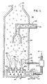
- FIG. 1 shows the hydrogen source 10 which is a hydrogen/oxygen generator.
- the water reservoir 2 is filled with natural water. Immersed in the water is an array of plates 3 of similar non-oxidizing material. Applied to plates 3 is a source 27 of pulsed direct current potential via electrical inlet 27. The action of the pulsed direct current, a voltage/current potential, on the plates causes the hydrogen atoms and oxygen atoms to become dissociated from the water molecule. Because the action is not a chemical action any natural water irrespective of source may be utilized.
- Varying either the potential of the direct current voltage source or the pulse rate of the pulsing of the direct current potential will vary proportionally the generation of the hydrogen/oxygen. Other factors are disclosed for varying the output of the generator. To replenish the expended water the generator provides a continuous water source 1.
- a safety valve 28 is rupturable upon excessive gas build-up.
- Switch 29 is a gas pressure switch to maintain a predetermined gas pressure level about a regulated low-volume.
- the generated hydrogen gas 4 is fed via pipe 5 to a gas mixing chamber 7, wherein the hydrogen gas is intermixed with exhaust gases 22 from a source hereinafter described.
- the mixture of hydrogen gas 4 and exhaust gases 22 is fed via pipe line 9 to a carburettor (air-mixture) system.
- the gas mixture 8 is fed through a nozzle to a chamber in a jet spray.
- the jet spray of gases combines with the intake air to form a gas mixture of hydrogen gas, which together with oxygen is entered into a combustion chamber.
- These exhaust gases 64 are fed via pipe line 24 to the gas mixing chamber 40.
- the pipeline 24 passes through cooling chamber 50 for cooling the gases therein.
- the cooling chamber 50 also functions as a spark arrestor to eliminate the possibility of gas ignition inside the mixing chamber 40. The excess exhaust gases are expelled into the atomsphere.
- the gases generated from the water in generator 10 also include the oxygen component of the water in addition to nitrogen.
- the outlet 5 on the generator 10 receives the oxygen and nitrogen gases generated thereby and feeds the same to the mixing chamber 40.
- the flow of the hydrogen gas is, of course, critical; therefore, there is incorporated in line 5 a gas flow valve to adjust the hydrogen flow.
- the gas mixture 8 which is generated and mixed in the arrangement of Figure 1, is directed by pipe line 9 and nozzle 11 to the cone 65.
- the gas mixture combines with air 14 as it enters cone area 65.
- the combined gas mixture, atomized by the jet nozzle 11 with air intake 14 is directed by the cone 65 to the dispersing chamber 66.
- the gas mixture 15 is further mixed with air 14 to form combustible gas 15.
- the gas/air mixture is dispersed via ports 67a xxx 67n from the dispersing chamber 66 into the firing area of the combustion chamber 60.
- the gas mixture 8 is also fed by pipeline 9 to a separation chamber 71. This chamber sections off a controlled amount of the intake gas mixture to the pilot light line 58.
- the pilot light firing gas 57 is also sequenced by the separation chamber 71 such as through an associated mechanical drive, much in the same manner as the cylinder of an automobile engine.
- the mixed gas 56a, 56n ejected from ports 67a xxx 67n of the dispensing chamber 66 is ignited by the pilot combustion 57 and thereby causes combustion of the mainstream gases.
- the cone 63 captures a portion of the exhaust gases 64.
- the captured exhaust gas is returned via pipe line 68 and outlet 74 to the combustion process as set in Figure 1 or expelled for other purposes.
- the major portion of the exhaust gases 64 by-pass the cone 63 and rise further to the outlet exhaust 69 and are expelled at opening 73.
- a gas regulator valve is utilized to reduce the pressure level inside the hydrogen generator 10. Once hydrogen generator 10 reaches an optimum gas pressure level, pressure switch 29 shuts off electrical power to the hydrogen exciters. If the chamber pressure exceeds a predetermined level, the safety release valve 28 is activated disconnecting the electrical current and thereby shutting down the entire system for safety inspection.
Landscapes
- Engineering & Computer Science (AREA)
- Chemical & Material Sciences (AREA)
- Combustion & Propulsion (AREA)
- Mechanical Engineering (AREA)
- General Engineering & Computer Science (AREA)
- Chemical Kinetics & Catalysis (AREA)
- General Chemical & Material Sciences (AREA)
- Oil, Petroleum & Natural Gas (AREA)
- Electrolytic Production Of Non-Metals, Compounds, Apparatuses Therefor (AREA)
- Output Control And Ontrol Of Special Type Engine (AREA)
Claims (1)
- Système à combustion pour la propulsion de systèmes mécaniques utilisant l'hydrogène gazeux comme carburant comprenant un générateur d'hydrogène/oxygène (10) produisant de l'hydrogène et de l'oxygène gazeux par un procédé d'électrolyse et mélangeant l'oxygène etl'hydrogène gazeux avec obtention d'un mélange gazeux uniforme, ayant un réservoir d'eau (2) rempli d'eau naturelle, une paire de plaques nonoxydantes similaires (3) disposées dans le réservoir d'eau (2), une source de tension continue (27) connectée aux plaques précitées afin de leur appliquer une tension électrique/bas courant et de dissocier les molécules d'eau précitée en hydrogène et oxygène gazeux, un dispositif de mélange d'air muni d'une admission d'air et dans lequel de l'air est mélangé avec le mélange d'hydrogène et d'oxygène gazeux, un brûleur de gaz (60) qui est alimenté avec une quantité contrôlée de mélange de gaz/air et qui comprend des moyens (57, 58) pour enflammer le mélange de gaz/air précité dans le brûleur de gaz (60) précité, et une sortie de gaz d'échappement, le système comprenant en outre un moyen de contrôle de la demande pour faire varier la libération d'hydrogène/oxygène gazeux à partir des molécules d'eau précitée caractérisé en ce quea) la source de tension continue (27) est une source de potentiel de courant continu pulsatoire pour dissocier les molécules d'eau précitées en hydrogène et oxygène et le moyen de contrôle de la demande fait varier le taux d'impulsions;b) une chambre de mélange du gaz d'échappement (7) est reliée au générateur d'hydrogène/oygène (10) et à un passage de retour du gaz d'échappement (68) du brûleur (60) et le mélange gazeux d'hydrogène et d'oxygène y est mélangé avec les gaz d'échappement (64) pour régler la vitesse de combustion de l'hydrogène,c) une chambre de refroidissement de gaz d'échappement (50) fonctionnant comme dispositif d'arrêt d'étincelles est prévue en amont de la chambre de mélange de gaz d'échappement (7),d) la chambre de mélange de gaz d'échappement (7) est reliée par l'intermédiaire d'une canalisation (9) à une chambre de distribution (71) à partir de laquelle les gaz mélangés sont amenés à une conduite d'allumage pilote (58) et à une conduite principale avec un gicleur (11),e) le dispositif de mélange d'air comprend un cône (65) à l'entrée d'un passage amenant à une chambre de dispersion (66) du brûleur de gaz (60), les gaz éjectés du gicleur et mélangés à l'air admis sont amenés par l'intermédiaire du cône (65) précité dans la chambre de dispersion qui est munie d'orifices de sorties (67a - 67n) à travers lesquels le mélange gazeux combustible est dispersé dans la chambre de combustion du brûleur de gaz (60).
Priority Applications (3)
| Application Number | Priority Date | Filing Date | Title |
|---|---|---|---|
| DE8282111596T DE3280356D1 (de) | 1982-12-14 | 1982-12-14 | Verbrennungseinrichtung fuer mechanische antriebssysteme unter verwendung von wasserstoffgas als brennstoff. |
| AT82111596T ATE67276T1 (de) | 1982-12-14 | 1982-12-14 | Verbrennungseinrichtung fuer mechanische antriebssysteme unter verwendung von wasserstoffgas als brennstoff. |
| EP82111596A EP0111574B1 (fr) | 1982-12-14 | 1982-12-14 | Système à combustion pour la propulsion de systèmes mécaniques utilisant l'hydrogène gazeux comme carburant |
Applications Claiming Priority (1)
| Application Number | Priority Date | Filing Date | Title |
|---|---|---|---|
| EP82111596A EP0111574B1 (fr) | 1982-12-14 | 1982-12-14 | Système à combustion pour la propulsion de systèmes mécaniques utilisant l'hydrogène gazeux comme carburant |
Publications (2)
| Publication Number | Publication Date |
|---|---|
| EP0111574A1 EP0111574A1 (fr) | 1984-06-27 |
| EP0111574B1 true EP0111574B1 (fr) | 1991-09-11 |
Family
ID=8189401
Family Applications (1)
| Application Number | Title | Priority Date | Filing Date |
|---|---|---|---|
| EP82111596A Expired - Lifetime EP0111574B1 (fr) | 1982-12-14 | 1982-12-14 | Système à combustion pour la propulsion de systèmes mécaniques utilisant l'hydrogène gazeux comme carburant |
Country Status (3)
| Country | Link |
|---|---|
| EP (1) | EP0111574B1 (fr) |
| AT (1) | ATE67276T1 (fr) |
| DE (1) | DE3280356D1 (fr) |
Cited By (1)
| Publication number | Priority date | Publication date | Assignee | Title |
|---|---|---|---|---|
| CN108915907A (zh) * | 2018-06-27 | 2018-11-30 | 江苏海事职业技术学院 | 一种egr废气再循环装置 |
Families Citing this family (2)
| Publication number | Priority date | Publication date | Assignee | Title |
|---|---|---|---|---|
| CA1231872A (fr) * | 1983-03-23 | 1988-01-26 | Stanley A. Meyer | Systeme injecteur d'hydrogene |
| AU2247299A (en) * | 1997-12-15 | 1999-07-05 | World Fusion Limited | Automobile engine system using water electrolytic gas |
Citations (5)
| Publication number | Priority date | Publication date | Assignee | Title |
|---|---|---|---|---|
| FR721354A (fr) * | 1931-08-14 | 1932-03-02 | Procédé et dispositif pour augmenter la puissance des moteurs d'automobiles et analogues | |
| US3982878A (en) * | 1975-10-09 | 1976-09-28 | Nissan Motor Co., Ltd. | Burning rate control in hydrogen fuel combustor |
| DE2641228A1 (de) * | 1976-09-14 | 1978-06-01 | Rudolf Werner Schmitz | Hydrogenium - (h) - wasserstoff - gasmotor fuer land- und wasserfahrzeuge jeder bauart mit diesel- und ottomotorantrieb, einschliesslich amphibienfahrzeuge |
| US4111160A (en) * | 1976-04-16 | 1978-09-05 | Talenti Pier F | Method and apparatus for operating combustion engines |
| FR2383247A1 (fr) * | 1977-03-10 | 1978-10-06 | Inoue Japax Res | Procede et appareil de fabrication d'oxygene et d'hydrogene gazeux par voie electrolytique |
Family Cites Families (9)
| Publication number | Priority date | Publication date | Assignee | Title |
|---|---|---|---|---|
| FR1178241A (fr) * | 1957-07-06 | 1959-05-05 | Appareil destiné à fabriquer un mélange gazeux détonant | |
| FR1187241A (fr) | 1957-11-23 | 1959-09-08 | Produits fertilisants et procédé pour leur fabrication | |
| US3616779A (en) | 1970-06-22 | 1971-11-02 | American Environmental Researc | Gas fueled internal combustion engine |
| US3648668A (en) * | 1970-07-08 | 1972-03-14 | Ebert Michael | Gas-operated internal combustion engine |
| US3971847A (en) * | 1973-12-26 | 1976-07-27 | The United States Of America As Represented By The Adminstrator Of The National Aeronautics And Space Administration | Hydrogen-rich gas generator |
| JPS51123422A (en) * | 1975-04-21 | 1976-10-28 | Nissan Motor Co Ltd | Fuel modulating system |
| GB1517799A (en) * | 1975-10-09 | 1978-07-12 | Nissan Motor | Burning rate control in hydrogen fuel combustor |
| FR2382247A1 (fr) | 1977-03-02 | 1978-09-29 | Petzl Pierre | Fixation reglable de ski de randonnee |
| GB2079441B (en) * | 1980-07-01 | 1984-04-18 | Defence Scretary Of State For | Evaporative miners |
-
1982
- 1982-12-14 DE DE8282111596T patent/DE3280356D1/de not_active Expired - Lifetime
- 1982-12-14 EP EP82111596A patent/EP0111574B1/fr not_active Expired - Lifetime
- 1982-12-14 AT AT82111596T patent/ATE67276T1/de active
Patent Citations (5)
| Publication number | Priority date | Publication date | Assignee | Title |
|---|---|---|---|---|
| FR721354A (fr) * | 1931-08-14 | 1932-03-02 | Procédé et dispositif pour augmenter la puissance des moteurs d'automobiles et analogues | |
| US3982878A (en) * | 1975-10-09 | 1976-09-28 | Nissan Motor Co., Ltd. | Burning rate control in hydrogen fuel combustor |
| US4111160A (en) * | 1976-04-16 | 1978-09-05 | Talenti Pier F | Method and apparatus for operating combustion engines |
| DE2641228A1 (de) * | 1976-09-14 | 1978-06-01 | Rudolf Werner Schmitz | Hydrogenium - (h) - wasserstoff - gasmotor fuer land- und wasserfahrzeuge jeder bauart mit diesel- und ottomotorantrieb, einschliesslich amphibienfahrzeuge |
| FR2383247A1 (fr) * | 1977-03-10 | 1978-10-06 | Inoue Japax Res | Procede et appareil de fabrication d'oxygene et d'hydrogene gazeux par voie electrolytique |
Cited By (2)
| Publication number | Priority date | Publication date | Assignee | Title |
|---|---|---|---|---|
| CN108915907A (zh) * | 2018-06-27 | 2018-11-30 | 江苏海事职业技术学院 | 一种egr废气再循环装置 |
| CN108915907B (zh) * | 2018-06-27 | 2020-06-09 | 江苏海事职业技术学院 | 一种egr废气再循环装置 |
Also Published As
| Publication number | Publication date |
|---|---|
| EP0111574A1 (fr) | 1984-06-27 |
| DE3280356D1 (de) | 1991-10-17 |
| ATE67276T1 (de) | 1991-09-15 |
Similar Documents
| Publication | Publication Date | Title |
|---|---|---|
| EP0086439B1 (fr) | Système d'injection d'hydrogène pour moteur à combustion interne | |
| US5887554A (en) | Rapid response plasma fuel converter systems | |
| US4319552A (en) | Pre-combustion system for internal combustion engines | |
| US4596210A (en) | Method and device for dissolving gas, especially carbon dioxide, in liquid fuel and for distributing the fuel in a supersaturated state through the combustion air | |
| JPH01318752A (ja) | 二液型推進剤ロケットエンジンの構造体 | |
| US12134990B2 (en) | System for remotely monitoring and controlling operation of a hydro-diesel engine | |
| US5722232A (en) | Hybrid helium heater pressurization system and electrical ignition system for pressure-fed hybrid rockets | |
| US20050011501A1 (en) | Multi-phase fuel system | |
| US6401445B1 (en) | Electrolysis system and method for improving fuel atomization and combustion | |
| KR100822733B1 (ko) | 내연기관용 워터가스 공급장치 | |
| EP0937196B1 (fr) | Procede de constitution d'un melange de carburant et d'allumage de ce melange dans une chambre de precombustion ouverte vers les cylindres | |
| JP2001524181A (ja) | 燃料誘導用分子反応装置 | |
| RU2045675C1 (ru) | Стендовая установка | |
| EP0111574A1 (fr) | Système à combustion pour la propulsion de systèmes mécaniques utilisant l'hydrogène gazeux comme carburant | |
| US1349876A (en) | Apparatus for burning fuel | |
| CA1231872A (fr) | Systeme injecteur d'hydrogene | |
| US2775866A (en) | Starters for prime movers such as gas turbines | |
| CA1227094A (fr) | Systeme de combustion a melangeur d'un dosage d'air et d'hydrogene avec un gaz non combustible | |
| US4925385A (en) | Fuel igniter | |
| RU2051289C1 (ru) | Способ приготовления топливовоздушной смеси для двигателя внутреннего сгорания и устройство для его осуществления | |
| JPH02527B2 (fr) | ||
| EP0101761A2 (fr) | Appareil pour la production de gaz à partir de l'eau et pour la combustion contrôlée de ces gaz | |
| KR900003476B1 (ko) | 액체 연료수(水) 첨가 초음파 연소 장치 | |
| RU2381417C1 (ru) | Горелка и способ работы горелки (варианты) | |
| US1349877A (en) | Liquid-fuel-ignition mechanism |
Legal Events
| Date | Code | Title | Description |
|---|---|---|---|
| PUAI | Public reference made under article 153(3) epc to a published international application that has entered the european phase |
Free format text: ORIGINAL CODE: 0009012 |
|
| AK | Designated contracting states |
Designated state(s): AT BE CH DE FR GB IT LI LU NL SE |
|
| 17P | Request for examination filed |
Effective date: 19841207 |
|
| GRAA | (expected) grant |
Free format text: ORIGINAL CODE: 0009210 |
|
| AK | Designated contracting states |
Kind code of ref document: B1 Designated state(s): AT BE CH DE FR GB IT LI LU NL SE |
|
| REF | Corresponds to: |
Ref document number: 67276 Country of ref document: AT Date of ref document: 19910915 Kind code of ref document: T |
|
| REF | Corresponds to: |
Ref document number: 3280356 Country of ref document: DE Date of ref document: 19911017 |
|
| ITF | It: translation for a ep patent filed | ||
| PGFP | Annual fee paid to national office [announced via postgrant information from national office to epo] |
Ref country code: GB Payment date: 19911223 Year of fee payment: 10 |
|
| PGFP | Annual fee paid to national office [announced via postgrant information from national office to epo] |
Ref country code: FR Payment date: 19911224 Year of fee payment: 10 Ref country code: CH Payment date: 19911224 Year of fee payment: 10 |
|
| ET | Fr: translation filed | ||
| PGFP | Annual fee paid to national office [announced via postgrant information from national office to epo] |
Ref country code: SE Payment date: 19911227 Year of fee payment: 10 Ref country code: AT Payment date: 19911227 Year of fee payment: 10 |
|
| PG25 | Lapsed in a contracting state [announced via postgrant information from national office to epo] |
Ref country code: LU Free format text: LAPSE BECAUSE OF NON-PAYMENT OF DUE FEES Effective date: 19911231 |
|
| PGFP | Annual fee paid to national office [announced via postgrant information from national office to epo] |
Ref country code: NL Payment date: 19911231 Year of fee payment: 10 |
|
| PGFP | Annual fee paid to national office [announced via postgrant information from national office to epo] |
Ref country code: DE Payment date: 19920110 Year of fee payment: 10 |
|
| PGFP | Annual fee paid to national office [announced via postgrant information from national office to epo] |
Ref country code: BE Payment date: 19920204 Year of fee payment: 10 |
|
| PLBE | No opposition filed within time limit |
Free format text: ORIGINAL CODE: 0009261 |
|
| STAA | Information on the status of an ep patent application or granted ep patent |
Free format text: STATUS: NO OPPOSITION FILED WITHIN TIME LIMIT |
|
| 26N | No opposition filed | ||
| PG25 | Lapsed in a contracting state [announced via postgrant information from national office to epo] |
Ref country code: GB Effective date: 19921214 Ref country code: AT Effective date: 19921214 |
|
| PG25 | Lapsed in a contracting state [announced via postgrant information from national office to epo] |
Ref country code: SE Effective date: 19921215 |
|
| PG25 | Lapsed in a contracting state [announced via postgrant information from national office to epo] |
Ref country code: LI Effective date: 19921231 Ref country code: CH Effective date: 19921231 Ref country code: BE Effective date: 19921231 |
|
| BERE | Be: lapsed |
Owner name: MEYER STANLEY A. Effective date: 19921231 |
|
| PG25 | Lapsed in a contracting state [announced via postgrant information from national office to epo] |
Ref country code: NL Effective date: 19930701 |
|
| GBPC | Gb: european patent ceased through non-payment of renewal fee |
Effective date: 19921214 |
|
| NLV4 | Nl: lapsed or anulled due to non-payment of the annual fee | ||
| PG25 | Lapsed in a contracting state [announced via postgrant information from national office to epo] |
Ref country code: FR Effective date: 19930831 |
|
| REG | Reference to a national code |
Ref country code: CH Ref legal event code: PL |
|
| PG25 | Lapsed in a contracting state [announced via postgrant information from national office to epo] |
Ref country code: DE Effective date: 19930901 |
|
| REG | Reference to a national code |
Ref country code: FR Ref legal event code: ST |
|
| EUG | Se: european patent has lapsed |
Ref document number: 82111596.1 Effective date: 19930709 |