EP0111579A1 - Projecteur de véhicule - Google Patents
Projecteur de véhicule Download PDFInfo
- Publication number
- EP0111579A1 EP0111579A1 EP82111722A EP82111722A EP0111579A1 EP 0111579 A1 EP0111579 A1 EP 0111579A1 EP 82111722 A EP82111722 A EP 82111722A EP 82111722 A EP82111722 A EP 82111722A EP 0111579 A1 EP0111579 A1 EP 0111579A1
- Authority
- EP
- European Patent Office
- Prior art keywords
- face
- shielding member
- reflector
- lamp
- reflecting face
- Prior art date
- Legal status (The legal status is an assumption and is not a legal conclusion. Google has not performed a legal analysis and makes no representation as to the accuracy of the status listed.)
- Withdrawn
Links
- 229920003002 synthetic resin Polymers 0.000 claims abstract description 12
- 239000000057 synthetic resin Substances 0.000 claims abstract description 12
- 230000003287 optical effect Effects 0.000 claims abstract description 9
- 239000011521 glass Substances 0.000 claims description 6
- BQCADISMDOOEFD-UHFFFAOYSA-N Silver Chemical compound [Ag] BQCADISMDOOEFD-UHFFFAOYSA-N 0.000 description 3
- 238000000034 method Methods 0.000 description 3
- 229910052709 silver Inorganic materials 0.000 description 3
- 239000004332 silver Substances 0.000 description 3
- 238000005422 blasting Methods 0.000 description 2
- 239000000463 material Substances 0.000 description 2
- 229910052751 metal Inorganic materials 0.000 description 2
- 239000002184 metal Substances 0.000 description 2
- QFVAWNPSRQWSDU-UHFFFAOYSA-N Dibenzthion Chemical compound C1N(CC=2C=CC=CC=2)C(=S)SCN1CC1=CC=CC=C1 QFVAWNPSRQWSDU-UHFFFAOYSA-N 0.000 description 1
- 239000004411 aluminium Substances 0.000 description 1
- 229910052782 aluminium Inorganic materials 0.000 description 1
- XAGFODPZIPBFFR-UHFFFAOYSA-N aluminium Chemical compound [Al] XAGFODPZIPBFFR-UHFFFAOYSA-N 0.000 description 1
- 239000007767 bonding agent Substances 0.000 description 1
- 239000011248 coating agent Substances 0.000 description 1
- 238000000576 coating method Methods 0.000 description 1
- 238000010276 construction Methods 0.000 description 1
- 230000000694 effects Effects 0.000 description 1
- 238000009499 grossing Methods 0.000 description 1
- 229910052736 halogen Inorganic materials 0.000 description 1
- 150000002367 halogens Chemical class 0.000 description 1
- 238000012986 modification Methods 0.000 description 1
- 230000004048 modification Effects 0.000 description 1
- 239000006060 molten glass Substances 0.000 description 1
- 238000000465 moulding Methods 0.000 description 1
- 238000007747 plating Methods 0.000 description 1
- 229920000515 polycarbonate Polymers 0.000 description 1
- 239000004417 polycarbonate Substances 0.000 description 1
Images




Classifications
-
- F—MECHANICAL ENGINEERING; LIGHTING; HEATING; WEAPONS; BLASTING
- F21—LIGHTING
- F21S—NON-PORTABLE LIGHTING DEVICES; SYSTEMS THEREOF; VEHICLE LIGHTING DEVICES SPECIALLY ADAPTED FOR VEHICLE EXTERIORS
- F21S45/00—Arrangements within vehicle lighting devices specially adapted for vehicle exteriors, for purposes other than emission or distribution of light
- F21S45/10—Protection of lighting devices
-
- F—MECHANICAL ENGINEERING; LIGHTING; HEATING; WEAPONS; BLASTING
- F21—LIGHTING
- F21S—NON-PORTABLE LIGHTING DEVICES; SYSTEMS THEREOF; VEHICLE LIGHTING DEVICES SPECIALLY ADAPTED FOR VEHICLE EXTERIORS
- F21S41/00—Illuminating devices specially adapted for vehicle exteriors, e.g. headlamps
- F21S41/10—Illuminating devices specially adapted for vehicle exteriors, e.g. headlamps characterised by the light source
- F21S41/14—Illuminating devices specially adapted for vehicle exteriors, e.g. headlamps characterised by the light source characterised by the type of light source
- F21S41/162—Incandescent light sources, e.g. filament or halogen lamps
- F21S41/164—Incandescent light sources, e.g. filament or halogen lamps having two or more filaments
-
- F—MECHANICAL ENGINEERING; LIGHTING; HEATING; WEAPONS; BLASTING
- F21—LIGHTING
- F21S—NON-PORTABLE LIGHTING DEVICES; SYSTEMS THEREOF; VEHICLE LIGHTING DEVICES SPECIALLY ADAPTED FOR VEHICLE EXTERIORS
- F21S41/00—Illuminating devices specially adapted for vehicle exteriors, e.g. headlamps
- F21S41/40—Illuminating devices specially adapted for vehicle exteriors, e.g. headlamps characterised by screens, non-reflecting members, light-shielding members or fixed shades
- F21S41/43—Illuminating devices specially adapted for vehicle exteriors, e.g. headlamps characterised by screens, non-reflecting members, light-shielding members or fixed shades characterised by the shape thereof
-
- F—MECHANICAL ENGINEERING; LIGHTING; HEATING; WEAPONS; BLASTING
- F21—LIGHTING
- F21S—NON-PORTABLE LIGHTING DEVICES; SYSTEMS THEREOF; VEHICLE LIGHTING DEVICES SPECIALLY ADAPTED FOR VEHICLE EXTERIORS
- F21S41/00—Illuminating devices specially adapted for vehicle exteriors, e.g. headlamps
- F21S41/30—Illuminating devices specially adapted for vehicle exteriors, e.g. headlamps characterised by reflectors
- F21S41/32—Optical layout thereof
- F21S41/321—Optical layout thereof the reflector being a surface of revolution or a planar surface, e.g. truncated
-
- F—MECHANICAL ENGINEERING; LIGHTING; HEATING; WEAPONS; BLASTING
- F21—LIGHTING
- F21S—NON-PORTABLE LIGHTING DEVICES; SYSTEMS THEREOF; VEHICLE LIGHTING DEVICES SPECIALLY ADAPTED FOR VEHICLE EXTERIORS
- F21S41/00—Illuminating devices specially adapted for vehicle exteriors, e.g. headlamps
- F21S41/30—Illuminating devices specially adapted for vehicle exteriors, e.g. headlamps characterised by reflectors
- F21S41/32—Optical layout thereof
- F21S41/33—Multi-surface reflectors, e.g. reflectors with facets or reflectors with portions of different curvature
- F21S41/338—Multi-surface reflectors, e.g. reflectors with facets or reflectors with portions of different curvature the reflector having surface portions added to its general concavity
Definitions
- the present invention relates to a vehicle headlamp and, more particularly, a vehicle headlamp provided with a front lens of synthetic resin.
- the conventional front lens employed to the vehicle headlamp is formed by press-molding a mass of molten glass, but a front lens made of synthetic resin has been developed because it can be light-weighted and because it enables a plurality of prisms to be easily formed for the purpose of controlling light radiated from a filament.
- a lens 1 made of synthetic resin is attached to the front end of a reflector 2.
- the reflector 2 has a reflecting parabolic face 3, to which is fixed a lamp holder 4 for attaching a lamp 6 to the reflector 2.
- the lamp 6 attached to the lamp holder 4 by means of a set spring 5 includes a main filament 8, a sub-filament 9 and a light shielding cap 10 inside a glass envelope 7, said light shielding cap 10 serving to cover about the lower half of said sub-filament 9.
- the main filament 8 is positioned nearly corresponding to the focussing point (f) of said reflector 2 while the sub-filament 9 is positioned ahead the focussing point (f) of said reflector 2.
- Numeral 11 represents a light shielding coat applied to the front end of said glass envelope 7.
- Vehicles are used under various circumstances such as on hot desert, for example.
- the headlamp attached to the vehicle which runs on such hot desert is brought under high temperature atmosphere. It is therefore necessary to test the headlamp to see if it can be used under high temperature atmosphere or at 80°C, for example.
- heat is concentrated to the upper area (A) of the lens 1, as shown in Fig. 1, because of high temperature atmosphere outside the headlamp, heat caused when focussed, and atmosphere caused hot inside the headlamp due to the turned-on lamp 6 and stayed in the headlamp at the upper portion thereof.
- the upper area (A) is softened by this concentrated heat.
- An object of the present invention is to reduce the amount of reflected light incident onto the upper area of synthetic resin lens and to prevent heat from being concentrated onto the upper area.
- Another object of the present invention is to provide a simple construction capable of preventing heat from being concentrated onto the upper area of synthetic resin lens.
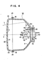
- a vehicle headlamp according to the present invention is shaped rectangular, for example, as shown in Fig. 3 and has a lens 20 attached to the front end of a reflector 30, as shown in Fig. 4.
- the lens 20 is made of transparent synthetic resin such as polycarbonate for example, and includes a lens face 21 formed on the inner surface thereof and provided with a plurality of prisms to control light, and a side wall 22 enclosing the lens face 21.
- the side wall 22 is air-tightly attached to the opened front end of said reflector 30 by means of a bonding agent 25 which is previously filled in a groove 32 formed on the opened front end face of said reflector 30.
- the reflector 30 has an about parabolic reflecting face 31, which includes an attachment hole in which is fixed a lamp holder 60 for attaching a lamp 50.
- the reflector 30 may be formed integral to the lamp holder 60.
- the lamp holder 60 is formed cylindrical so as to allow a glass envelope 51 for the lamp 50 to be inserted therethrough, and has a stepped portion 61 formed on the inner face thereof on which a flange 52 of said lamp 50 is rested.
- the flange 52 is urged against the stepped portion 61 by means of a set spring 65, thus enabling the lamp 50 to be attached to the lamp holder 60.
- the lamp holder 60 is made of synthetic resin when the reflector 30 is made of synthetic resin but that the former is made of metal when the latter is made of mecal.
- the lamp 50 includes a main filament 54, a sub-filament 55 and a light shielding cap 56 inside the glass envelope 51 to the front end of which is applied a light shielding coat 53, said light shielding cap 56 covering about the lower half of said sub-filament 55.
- the sub-filament 55 is position ahead the main filament 54 inside the glass envelope 51.
- the lamp 50 thus arranged may be of Halogen H 4 according to ECE regulation.
- the lamp 50 is attached to the lamp holder 60 in such a way that the sub-filament 55 is positioned ahead the focussing point (f) of the reflector 30, and that the main filament 54 is positioned nearly corresponding to the focussing point (f).
- the sub-filament 55 is positioned ahead the focussing point (f) with its center lying on the optical axis (X), while the main filament 54 is positioned contacted with the optical axis (X) and the focussing point (f) but with its center lying under the optical axis (X).
- the main filament 54 is used as upper beam and the sub-filament 55 as dipped beam.
- the reflecting parabolic face 31 is formed by vaporing a reflecting coat such as aluminium, for example, on to the parabolic face of reflector body.
- a reflecting coat such as aluminium, for example
- the reflector body is made of metal or synthetic resin such as poly- buthylene terephthalete, for example, it is preferable that an undercoat is interposed between the reflector body and the reflecting coat for the purpose of smoothing the reflecting coat.
- the reflecting face 31 has a zone 31a where light of the sub-filament 55 is reflected to the upper area (A) of the lens face 21. As shown in Fig. 3, the zone 31a is above the lamp 50 and along a line (Y) vertically passing through the optical axis (X). The zone 31a is shielded by a shielding member 40 arranged between the reflecting face 31 and the lamp 50.
- the shielding member 40 is a metallic plate and has such area that enables light of sub-filament to be prevented from entering into the zone 31a.
- the shielding member 40 is fitted between rails 62 and 63 formed on the front end face of said lamp holder 60, and kept substantially parallel to the optical axis (X) as shown in Fig. 4, thus achieving a design effect of keeping the shielding member 40 invisible from the front when the headlamp is turned off.
- the whole of said shielding member 40 may be subjected to a process of letting light be absorbed as much as possible, such as the application of black plating or coating.
- one face of said shielding member 40 located on the side of the reflecting face 31 is silver-plated, white or silver-coated, or aluminium-vapored to form a reflecting face 41. This is because one's eyes reflected by the zone 31a is absorbed by the light absorbing face, thus causing the viewer to see the inside of the headlamp quite dark, when the face of said shielding member 40 located on the side of the reflecting face 31 is subjected to light-absorbing process. It is also preferable that the other face of said shielding member 40 located on the side of said lamp 50 is processed to form a light absorbing face 42 so as to prevent light from being reflected as little as possible.
- the zone in the reflecting parabolic face which is projected onto the area of said lens face is shielded by the shielding member, as described above.
- the area can be kept lower in temperature and thus prevented from becoming softened.
- the shielding member can be easily attached to the lamp holder.
- Fig. 5 is a sectional view showing another embodiment of the present invention. Same parts as those in the above-described embodiment will be represented by same numerals and description on these parts will be omitted.
- the shielding member 40 for shielding the zone 31a is curved along the reflecting parabolic face 31 and attached to a stand 64 formed on the lamp holder 60 by means of screws 70 in this second embodiment.
- Light absorbing process may be applied to the whole of said shielding member 40, but the face of said shielding member 40 located on the side of the lamp 50 is formed as an irregularly reflecting face 43 for the sake of visibility when viewed from the front.
- the material surface of said shielding member 40 is made rough and uneven by shot-blasting, for example, and then aluminium-vapored or silver-coated to form the irregularly reflecting face 43.
- the other face of said shielding member 40 located on the side of the reflecting face 31 may be formed either as light absorbing face or as irregularly reflecting face, and it is formed as a light absorbing face 42 in this second embodiment.
- Fig. 6 is a sectional view showing a further embodiment of the present invention and Fig. 7 is a partially cutaway perspective view showing the shielding member 40 of Fig. 6 enlarged.
- Same parts as those in the above-described embodiments will also be represented by same reference numerals and description on these parts will be omitted, too.
- the shielding member 40 for shielding the zone 31a is arranged between the reflecting face 31 and the lamp 50 and attached at one end thereof to an upper flat wall 33 of said reflector 30 by means of rivets 71.
- the shielding member 40 shields even the reflecting face 31 of said reflector 30 in addition to the zone 31a thereof in this third embodiment. Therefore, this portion of said shielding member 40 which is located on the side of the lamp 50 and which is intended to shield the reflecting face 31 is formed as a reflecting parabolic face 44 which has same focussing point as that (f) of said reflecting face 31, while that portion of said shielding member 40 which is located on the side of the lamp 50 and which is intended to shield the zone 31a is formed as an irregularly reflecting face 43.
Landscapes
- Engineering & Computer Science (AREA)
- General Engineering & Computer Science (AREA)
- Non-Portable Lighting Devices Or Systems Thereof (AREA)
Priority Applications (1)
| Application Number | Priority Date | Filing Date | Title |
|---|---|---|---|
| EP82111722A EP0111579A1 (fr) | 1982-12-17 | 1982-12-17 | Projecteur de véhicule |
Applications Claiming Priority (1)
| Application Number | Priority Date | Filing Date | Title |
|---|---|---|---|
| EP82111722A EP0111579A1 (fr) | 1982-12-17 | 1982-12-17 | Projecteur de véhicule |
Publications (1)
| Publication Number | Publication Date |
|---|---|
| EP0111579A1 true EP0111579A1 (fr) | 1984-06-27 |
Family
ID=8189408
Family Applications (1)
| Application Number | Title | Priority Date | Filing Date |
|---|---|---|---|
| EP82111722A Withdrawn EP0111579A1 (fr) | 1982-12-17 | 1982-12-17 | Projecteur de véhicule |
Country Status (1)
| Country | Link |
|---|---|
| EP (1) | EP0111579A1 (fr) |
Cited By (6)
| Publication number | Priority date | Publication date | Assignee | Title |
|---|---|---|---|---|
| US4825344A (en) * | 1986-02-20 | 1989-04-25 | Stanley Electric Co., Ltd. | Headlamp for vehicles |
| DE4126044A1 (de) * | 1990-08-07 | 1992-02-20 | Koito Mfg Co Ltd | Schirmanordnung fuer eine doppelfaden-gluehlampe in einem fahrzeugscheinwerfer |
| EP0548555A1 (fr) * | 1991-12-21 | 1993-06-30 | Hella KG Hueck & Co. | Projecteur pour véhicule |
| DE4204200A1 (de) * | 1992-02-13 | 1993-08-19 | Daimler Benz Ag | Fluessigkeit und deren verwendung |
| ES2051171A2 (es) * | 1990-11-19 | 1994-06-01 | Koito Mfg Co Ltd | Faro de automovil. |
| DE4413833A1 (de) * | 1993-04-20 | 1994-11-10 | Koito Mfg Co Ltd | Fahrzeugscheinwerfer |
Citations (4)
| Publication number | Priority date | Publication date | Assignee | Title |
|---|---|---|---|---|
| US1644686A (en) * | 1925-11-05 | 1927-10-11 | Emerich J Markel | Reflector attachment for vehicle headlights |
| FR2125674A5 (fr) * | 1971-02-16 | 1972-09-29 | Ducellier & Cie | |
| GB2011600A (en) * | 1977-12-29 | 1979-07-11 | Cibie Projecteurs | Vehicle headlights |
| GB2079434A (en) * | 1980-06-06 | 1982-01-20 | Seima | Protecting headlamp lenses from damage by heat |
-
1982
- 1982-12-17 EP EP82111722A patent/EP0111579A1/fr not_active Withdrawn
Patent Citations (4)
| Publication number | Priority date | Publication date | Assignee | Title |
|---|---|---|---|---|
| US1644686A (en) * | 1925-11-05 | 1927-10-11 | Emerich J Markel | Reflector attachment for vehicle headlights |
| FR2125674A5 (fr) * | 1971-02-16 | 1972-09-29 | Ducellier & Cie | |
| GB2011600A (en) * | 1977-12-29 | 1979-07-11 | Cibie Projecteurs | Vehicle headlights |
| GB2079434A (en) * | 1980-06-06 | 1982-01-20 | Seima | Protecting headlamp lenses from damage by heat |
Cited By (6)
| Publication number | Priority date | Publication date | Assignee | Title |
|---|---|---|---|---|
| US4825344A (en) * | 1986-02-20 | 1989-04-25 | Stanley Electric Co., Ltd. | Headlamp for vehicles |
| DE4126044A1 (de) * | 1990-08-07 | 1992-02-20 | Koito Mfg Co Ltd | Schirmanordnung fuer eine doppelfaden-gluehlampe in einem fahrzeugscheinwerfer |
| ES2051171A2 (es) * | 1990-11-19 | 1994-06-01 | Koito Mfg Co Ltd | Faro de automovil. |
| EP0548555A1 (fr) * | 1991-12-21 | 1993-06-30 | Hella KG Hueck & Co. | Projecteur pour véhicule |
| DE4204200A1 (de) * | 1992-02-13 | 1993-08-19 | Daimler Benz Ag | Fluessigkeit und deren verwendung |
| DE4413833A1 (de) * | 1993-04-20 | 1994-11-10 | Koito Mfg Co Ltd | Fahrzeugscheinwerfer |
Similar Documents
| Publication | Publication Date | Title |
|---|---|---|
| US4506315A (en) | Vehicle headlamp | |
| US4563730A (en) | Vehicle head lamp with synthetic resin reflector and ring-shaped heat shielding member | |
| US6123440A (en) | Automobile headlight and optical unit with hyperbolic reflector and plano-convex or toric convergent lens | |
| US5544021A (en) | Motor vehicle headlight including a two-filament lamp for selectively generating a main beam and an anti-fog beam | |
| US5021930A (en) | Automotive headlamp having reduced chromatic aberration | |
| AU6071686A (en) | Masked headlight for motor vehicles | |
| GB2240617A (en) | Vehicle headlight | |
| US5113321A (en) | Vehicular lamp | |
| EP0111579A1 (fr) | Projecteur de véhicule | |
| EP0112397A1 (fr) | Projecteur de véhicule | |
| SE8405490D0 (sv) | Halvljusstralkastare for motorfordon | |
| US2858467A (en) | Vehicle headlamp | |
| EP0384589B1 (fr) | Réflecteur pour lampe | |
| US4308574A (en) | Automobile headlight with reduced heating of the cover glass | |
| US3136914A (en) | Vehicle headlamp and filament shield therefor | |
| US6093999A (en) | Vehicle lamp with shaped envelope interior providing a light-trapping dome | |
| ES259198U (es) | Bloque optico de alumbrado,especialmente para proyectores devehiculos automoviles | |
| JPS6118561Y2 (fr) | ||
| EP0884522B1 (fr) | Projecteur de véhicule automobile comportant une lampe à deux filaments | |
| JPH04357602A (ja) | 車両用灯具 | |
| JPS6137124Y2 (fr) | ||
| JPH0572006U (ja) | プロジェクタ型前照灯 | |
| JPS6137121Y2 (fr) | ||
| JPS6137122Y2 (fr) | ||
| JPH0610562Y2 (ja) | プロジェクタ型ヘッドランプ |
Legal Events
| Date | Code | Title | Description |
|---|---|---|---|
| PUAI | Public reference made under article 153(3) epc to a published international application that has entered the european phase |
Free format text: ORIGINAL CODE: 0009012 |
|
| AK | Designated contracting states |
Designated state(s): DE FR GB NL |
|
| STAA | Information on the status of an ep patent application or granted ep patent |
Free format text: STATUS: THE APPLICATION IS DEEMED TO BE WITHDRAWN |
|
| 18D | Application deemed to be withdrawn |
Effective date: 19850228 |
|
| RIN1 | Information on inventor provided before grant (corrected) |
Inventor name: HASEGAWA, TATSUMI Inventor name: MAEKAWA, MASASHI |