EP0111733A2 - Flüssigkeitsempfindliches Element - Google Patents
Flüssigkeitsempfindliches Element Download PDFInfo
- Publication number
- EP0111733A2 EP0111733A2 EP83111248A EP83111248A EP0111733A2 EP 0111733 A2 EP0111733 A2 EP 0111733A2 EP 83111248 A EP83111248 A EP 83111248A EP 83111248 A EP83111248 A EP 83111248A EP 0111733 A2 EP0111733 A2 EP 0111733A2
- Authority
- EP
- European Patent Office
- Prior art keywords
- electrodes
- sensitive element
- liquid
- resistance
- resistance heating
- Prior art date
- Legal status (The legal status is an assumption and is not a legal conclusion. Google has not performed a legal analysis and makes no representation as to the accuracy of the status listed.)
- Granted
Links
- 239000007788 liquid Substances 0.000 title claims abstract description 17
- 238000010438 heat treatment Methods 0.000 claims abstract description 20
- 238000000034 method Methods 0.000 claims abstract description 12
- 239000004020 conductor Substances 0.000 claims abstract description 9
- 230000002441 reversible effect Effects 0.000 claims abstract description 5
- 238000003475 lamination Methods 0.000 claims abstract description 4
- 239000000126 substance Substances 0.000 claims description 10
- 239000003054 catalyst Substances 0.000 claims description 8
- 238000001465 metallisation Methods 0.000 claims description 7
- 239000011810 insulating material Substances 0.000 claims description 6
- 239000004071 soot Substances 0.000 claims description 2
- 239000002245 particle Substances 0.000 abstract description 13
- OKTJSMMVPCPJKN-UHFFFAOYSA-N Carbon Chemical compound [C] OKTJSMMVPCPJKN-UHFFFAOYSA-N 0.000 abstract description 4
- 229910052799 carbon Inorganic materials 0.000 abstract description 3
- 229910052751 metal Inorganic materials 0.000 description 11
- 239000002184 metal Substances 0.000 description 11
- RYGMFSIKBFXOCR-UHFFFAOYSA-N Copper Chemical compound [Cu] RYGMFSIKBFXOCR-UHFFFAOYSA-N 0.000 description 7
- 239000011230 binding agent Substances 0.000 description 7
- 229910052802 copper Inorganic materials 0.000 description 7
- 239000010949 copper Substances 0.000 description 7
- 239000000945 filler Substances 0.000 description 7
- 150000002739 metals Chemical class 0.000 description 6
- 230000000694 effects Effects 0.000 description 5
- 239000011521 glass Substances 0.000 description 5
- 230000008569 process Effects 0.000 description 5
- -1 argon ions Chemical class 0.000 description 4
- 239000000463 material Substances 0.000 description 4
- 229920003023 plastic Polymers 0.000 description 4
- 239000004033 plastic Substances 0.000 description 4
- BASFCYQUMIYNBI-UHFFFAOYSA-N platinum Substances [Pt] BASFCYQUMIYNBI-UHFFFAOYSA-N 0.000 description 4
- 230000004044 response Effects 0.000 description 4
- 238000007650 screen-printing Methods 0.000 description 4
- VYPSYNLAJGMNEJ-UHFFFAOYSA-N Silicium dioxide Chemical compound O=[Si]=O VYPSYNLAJGMNEJ-UHFFFAOYSA-N 0.000 description 3
- HEMHJVSKTPXQMS-UHFFFAOYSA-M Sodium hydroxide Chemical compound [OH-].[Na+] HEMHJVSKTPXQMS-UHFFFAOYSA-M 0.000 description 3
- 150000002736 metal compounds Chemical class 0.000 description 3
- TWNQGVIAIRXVLR-UHFFFAOYSA-N oxo(oxoalumanyloxy)alumane Chemical compound O=[Al]O[Al]=O TWNQGVIAIRXVLR-UHFFFAOYSA-N 0.000 description 3
- IJGRMHOSHXDMSA-UHFFFAOYSA-N Atomic nitrogen Chemical compound N#N IJGRMHOSHXDMSA-UHFFFAOYSA-N 0.000 description 2
- GWEVSGVZZGPLCZ-UHFFFAOYSA-N Titan oxide Chemical compound O=[Ti]=O GWEVSGVZZGPLCZ-UHFFFAOYSA-N 0.000 description 2
- 229910052782 aluminium Inorganic materials 0.000 description 2
- 239000012876 carrier material Substances 0.000 description 2
- 238000005516 engineering process Methods 0.000 description 2
- 229910052737 gold Inorganic materials 0.000 description 2
- 239000000203 mixture Substances 0.000 description 2
- 229910052697 platinum Inorganic materials 0.000 description 2
- 239000002296 pyrolytic carbon Substances 0.000 description 2
- 238000007788 roughening Methods 0.000 description 2
- XLYOFNOQVPJJNP-UHFFFAOYSA-N water Chemical compound O XLYOFNOQVPJJNP-UHFFFAOYSA-N 0.000 description 2
- LRXTYHSAJDENHV-UHFFFAOYSA-H zinc phosphate Chemical compound [Zn+2].[Zn+2].[Zn+2].[O-]P([O-])([O-])=O.[O-]P([O-])([O-])=O LRXTYHSAJDENHV-UHFFFAOYSA-H 0.000 description 2
- 208000007101 Muscle Cramp Diseases 0.000 description 1
- 229910052581 Si3N4 Inorganic materials 0.000 description 1
- 239000005083 Zinc sulfide Substances 0.000 description 1
- 239000011354 acetal resin Substances 0.000 description 1
- 239000000853 adhesive Substances 0.000 description 1
- 230000001070 adhesive effect Effects 0.000 description 1
- ILRRQNADMUWWFW-UHFFFAOYSA-K aluminium phosphate Chemical compound O1[Al]2OP1(=O)O2 ILRRQNADMUWWFW-UHFFFAOYSA-K 0.000 description 1
- XKRFYHLGVUSROY-UHFFFAOYSA-N argon Substances [Ar] XKRFYHLGVUSROY-UHFFFAOYSA-N 0.000 description 1
- 229910052786 argon Inorganic materials 0.000 description 1
- 239000003990 capacitor Substances 0.000 description 1
- 239000006229 carbon black Substances 0.000 description 1
- 230000003197 catalytic effect Effects 0.000 description 1
- 229910001567 cementite Inorganic materials 0.000 description 1
- 239000000919 ceramic Substances 0.000 description 1
- 230000008859 change Effects 0.000 description 1
- 238000005234 chemical deposition Methods 0.000 description 1
- HGAZMNJKRQFZKS-UHFFFAOYSA-N chloroethene;ethenyl acetate Chemical compound ClC=C.CC(=O)OC=C HGAZMNJKRQFZKS-UHFFFAOYSA-N 0.000 description 1
- 238000011109 contamination Methods 0.000 description 1
- 125000005442 diisocyanate group Chemical group 0.000 description 1
- 238000001035 drying Methods 0.000 description 1
- 239000003822 epoxy resin Substances 0.000 description 1
- 230000002349 favourable effect Effects 0.000 description 1
- 239000007789 gas Substances 0.000 description 1
- 230000035784 germination Effects 0.000 description 1
- 239000010439 graphite Substances 0.000 description 1
- 229910002804 graphite Inorganic materials 0.000 description 1
- 125000002887 hydroxy group Chemical group [H]O* 0.000 description 1
- 238000005468 ion implantation Methods 0.000 description 1
- 150000002500 ions Chemical class 0.000 description 1
- 229910000464 lead oxide Inorganic materials 0.000 description 1
- 238000004519 manufacturing process Methods 0.000 description 1
- 238000005259 measurement Methods 0.000 description 1
- 229910044991 metal oxide Inorganic materials 0.000 description 1
- 150000004706 metal oxides Chemical class 0.000 description 1
- 238000004377 microelectronic Methods 0.000 description 1
- 230000005012 migration Effects 0.000 description 1
- 238000013508 migration Methods 0.000 description 1
- 229910052757 nitrogen Inorganic materials 0.000 description 1
- YEXPOXQUZXUXJW-UHFFFAOYSA-N oxolead Chemical compound [Pb]=O YEXPOXQUZXUXJW-UHFFFAOYSA-N 0.000 description 1
- BPUBBGLMJRNUCC-UHFFFAOYSA-N oxygen(2-);tantalum(5+) Chemical compound [O-2].[O-2].[O-2].[O-2].[O-2].[Ta+5].[Ta+5] BPUBBGLMJRNUCC-UHFFFAOYSA-N 0.000 description 1
- 238000012856 packing Methods 0.000 description 1
- 229910052763 palladium Inorganic materials 0.000 description 1
- NBIIXXVUZAFLBC-UHFFFAOYSA-K phosphate Chemical compound [O-]P([O-])([O-])=O NBIIXXVUZAFLBC-UHFFFAOYSA-K 0.000 description 1
- 230000000704 physical effect Effects 0.000 description 1
- 238000007747 plating Methods 0.000 description 1
- 229920000647 polyepoxide Polymers 0.000 description 1
- 229920000728 polyester Polymers 0.000 description 1
- 229920000642 polymer Polymers 0.000 description 1
- 229920006324 polyoxymethylene Polymers 0.000 description 1
- 229920002635 polyurethane Polymers 0.000 description 1
- 239000004814 polyurethane Substances 0.000 description 1
- 239000011148 porous material Substances 0.000 description 1
- 238000001556 precipitation Methods 0.000 description 1
- 238000007639 printing Methods 0.000 description 1
- 230000005855 radiation Effects 0.000 description 1
- 230000009467 reduction Effects 0.000 description 1
- 229920006395 saturated elastomer Polymers 0.000 description 1
- 239000000377 silicon dioxide Substances 0.000 description 1
- 235000012239 silicon dioxide Nutrition 0.000 description 1
- HQVNEWCFYHHQES-UHFFFAOYSA-N silicon nitride Chemical compound N12[Si]34N5[Si]62N3[Si]51N64 HQVNEWCFYHHQES-UHFFFAOYSA-N 0.000 description 1
- 229910052814 silicon oxide Inorganic materials 0.000 description 1
- 229920002050 silicone resin Polymers 0.000 description 1
- 229910052709 silver Inorganic materials 0.000 description 1
- 238000002791 soaking Methods 0.000 description 1
- 238000004544 sputter deposition Methods 0.000 description 1
- 229910001936 tantalum oxide Inorganic materials 0.000 description 1
- XOLBLPGZBRYERU-UHFFFAOYSA-N tin dioxide Chemical compound O=[Sn]=O XOLBLPGZBRYERU-UHFFFAOYSA-N 0.000 description 1
- 229910001887 tin oxide Inorganic materials 0.000 description 1
- 239000004408 titanium dioxide Substances 0.000 description 1
- 238000005019 vapor deposition process Methods 0.000 description 1
- 229910052984 zinc sulfide Inorganic materials 0.000 description 1
- DRDVZXDWVBGGMH-UHFFFAOYSA-N zinc;sulfide Chemical compound [S-2].[Zn+2] DRDVZXDWVBGGMH-UHFFFAOYSA-N 0.000 description 1
Images

Classifications
-
- G—PHYSICS
- G01—MEASURING; TESTING
- G01N—INVESTIGATING OR ANALYSING MATERIALS BY DETERMINING THEIR CHEMICAL OR PHYSICAL PROPERTIES
- G01N27/00—Investigating or analysing materials by the use of electric, electrochemical, or magnetic means
- G01N27/02—Investigating or analysing materials by the use of electric, electrochemical, or magnetic means by investigating impedance
- G01N27/04—Investigating or analysing materials by the use of electric, electrochemical, or magnetic means by investigating impedance by investigating resistance
- G01N27/12—Investigating or analysing materials by the use of electric, electrochemical, or magnetic means by investigating impedance by investigating resistance of a solid body in dependence upon absorption of a fluid; of a solid body in dependence upon reaction with a fluid, for detecting components in the fluid
- G01N27/121—Investigating or analysing materials by the use of electric, electrochemical, or magnetic means by investigating impedance by investigating resistance of a solid body in dependence upon absorption of a fluid; of a solid body in dependence upon reaction with a fluid, for detecting components in the fluid for determining moisture content, e.g. humidity, of the fluid
Definitions
- the invention is based on a liquid-sensitive element according to the preamble of claim 1.
- a capacitive moisture sensor is already known from DE-PS 29 38 434, in which two electrodes which are electrically insulated from one another are applied to a moisture-insensitive carrier material made of metal, glass or ceramic by means of a vapor deposition process. These electrodes made of Au, Ag, Pt or Al are comb-shaped in order to achieve a sufficient capacitive effect and interlock.
- high-frequency cathode sputtering overlies a moisture-sensitive capacitor dielectric which is both sputterable and has sufficient reversible affinity for moisture.
- silicon nitride, tantalum oxide or zinc sulfide are also used.
- this sputtered layer must be subjected to a roughening process.
- the roughening process is carried out using nitrogen or argon ions of predetermined energy in an ion implantation system.
- the degree of porosity of the layer is adjusted via the radiation dose.
- a sensor for detecting condensed moisture is described in DE-PS 26 27 441. It is used to control an electric heater that turns on when there is ice, hoarfrost, or condensed moisture on a glass plate.
- a change in current or impedance occurs between the electrodes, which changes are used to control the heating device.
- a glass plate, an aluminum oxide plate or a heat-resistant plastic plate is used as the carrier material, on which the electrodes made of a conductive material with a high chemical resistance are applied, for example in a screen printing process.
- a conductive metal oxide such as Ru0 2 , In 2 0 3 , Sno 21 V 2 0 5 or a conductive, not easily migrating metal, such as Au, Pd, Pt or Al, are used, which are mixed with a glass frit.
- a layer of zinc orthophosphate is applied between the electrodes. If moisture gets on it, the orthophosphate dissolves in the condensed moisture and dissociates. When the moisture disappears, the ions are combined again to form zinc orthophosphate.
- the surface of the anti-fog glass plate equipped with the sensor is heated as soon as the resistance of the sensor reaches 0.5 M ⁇ when the moisture is deposited, and is heated by printed heating element strips. The fogging disappears and the resistance of the sensor reaches 1 M ⁇ . As soon as this value is reached, the current is switched off.
- a rain sensor for a rain collector is known from DE-GM 81 21 939, in which comb-like electrodes are applied to a plastic plate on the top.
- Four wire resistors are provided for heating, which are located on the underside of the plastic plate.
- the housing in which the plastic plate is inserted is installed at an incline of 20 degrees so that excess rainwater can drain off. The function is adequately guaranteed by the heating, especially in the cold season and when there is snow. It also ensures that the sensor dries out after the precipitation has ended.
- the object of the present invention is to provide a liquid-sensitive element with a short response time and a long service life, which has a simple structure, can be manufactured cost-effectively, is better protected against contamination and is energy-saving with respect to heating.
- the resistance heating layer is on the same side as the electrodes, only the relatively thin insulating layer needs to be heated by the heating, but not the insulating plate, which is relatively thick. This means that this element is more energy efficient with the same effect and it also has a shorter response time.
- the liquid-sensitive element consists of a rectangular, flat insulating material plate 1, preferably made of hard paper, onto which the connecting conductor tracks 2 for the resistance heating layer 3 are e.g. are applied using screen printing technology.
- Resistance paste e.g. a pyropolymer resistance paste core-catalyzed for chemical copper plating. The resistance value of the paste is of subordinate importance, since the connecting conductor tracks in a chemical bath are anyway reinforced by chemical metal deposition, the metal being electrically conductive with low resistance.
- the copper-containing pyropolymer resistance paste is a paste that consists of a binder to which the conductive particles and the catalyst substance are admixed.
- a binder to which the conductive particles and the catalyst substance are admixed.
- Mixtures of caprolactam-blocked polyurethane with silicone resins and / or acetal resins and / or vinyl chloride-vinyl acetate polymers and / or saturated polyesters can be used as binders.
- the binders can also be a caprolactam-blocked adduct of isoporone diisocyanate and a hydroxyl-containing oxyester.
- the resistance value depends on the type and packing density of the pyropolymers.
- These are electrically conductive particles that are coated with pyrolytic carbon.
- the particles consist of aluminum phosphate, aluminum oxide, silicon dioxide, titanium dioxide, iron carbide, tin oxide or lead oxide. Carbon black, graphite or mixtures can also be added to the binder as conductive particles.
- catalysts in the binder which are effective for the chemical metal deposition of the connecting conductor tracks.
- the term "catalytic” is to be understood as meaning a substance or a material which effects the metal deposition from chemically working baths.
- Such fillers which are effective for chemical metal deposition, form catalytically active centers on the surface and in the pore system of the binder, at which a well-adhering metal layer can be built up from a chemically working metallization bath.
- Metals or metal compounds of copper and / or the platinum group are used as catalysts.
- the catalysts can be added to the binder separately from the refractory particles coated with pyrolytic carbon. On the other hand, these particles coated with carbon can also be germinated with the catalysts.
- particles of metals or metal compounds are deposited on the filler particles.
- other metals can also be used to germinate the filler. The selection of these metals is made depending on the metal deposition solution to be used later.
- the metal compounds of copper, such as copper I-oxide, are, however, very special as catalysts for the copper metals suitable.
- Germination of the filler materials is preferably carried out by soaking the filler particles with a copper-I-chloride solution and the copper-I-chloride absorbed on the filler particle surface by, for example, exposure to NaOH in the practically water-insoluble copper-I-oxide is converted.
- the resistance heating layer 3 is applied in a screen printing process in the next step.
- This layer also consists of a pyropolymer resistance paste, the resistance value of which is usually somewhat higher than that of the connecting conductor tracks 2.
- the catalysts that are important for chemical deposition are missing in this paste.
- Electrodes 5, 6 There is an insulating layer 4 above the resistance heating layer 3, in which the electrodes 5, 6 are embedded. These electrodes consist of two longitudinal electrodes 5, which extend at the edge parallel to the two long sides of the insulating material plate 1, and comb-shaped tines 6, which alternately run inward from the two longitudinal electrodes 5, but do not touch. If an electrically conductive liquid gets between the tines, the previously very high resistance is reduced and this reduction can e.g. be used to display rain.
- the relatively thin insulating layer 4, which is located between the resistance heating layer 3 and the electrodes 5, 6, is easier to heat up than the comparatively thick insulating plate 1.
- the element thus has a shorter response time. It is also more energy efficient since less energy is needed to achieve the same effect, namely drying the smooth surface of the element.
- the insulating layer 4 is applied together with the electrodes 5, 6 using the so-called reverse lamination technique.
- this technique one first starts from an intermediate carrier on which the electrodes are applied in the desired layout, preferably by printing in the screen printing process. Then the structure is hardened and coated with the Teten side on the insulating plate 1, which is already provided with the resistance heating layer, laminated using an epoxy resin adhesive as an insulating layer. In a final process step, the intermediate carrier is removed or completely etched away. The connection points on the conductor tracks or electrodes for rivets or cramps are covered beforehand by means of a cover.
- the material for the electrodes 5, 6 consists of a low-resistance, soot-containing paste. This paste shows no signs of migration in high humidity or in the presence of liquid.
- a low-resistance paste made of pyrolytically carbon-coated temperature-resistant particles can also be used.
- the element can not only be used as a rain sensor, but also wherever it is important to indicate the presence of conductive liquids.
Landscapes
- Chemical & Material Sciences (AREA)
- Chemical Kinetics & Catalysis (AREA)
- Electrochemistry (AREA)
- Physics & Mathematics (AREA)
- Health & Medical Sciences (AREA)
- Life Sciences & Earth Sciences (AREA)
- Analytical Chemistry (AREA)
- Biochemistry (AREA)
- General Health & Medical Sciences (AREA)
- General Physics & Mathematics (AREA)
- Immunology (AREA)
- Pathology (AREA)
- Surface Heating Bodies (AREA)
- Resistance Heating (AREA)
- Investigating Or Analyzing Materials By The Use Of Fluid Adsorption Or Reactions (AREA)
- Investigating Or Analyzing Materials By The Use Of Electric Means (AREA)
- Measurement Of The Respiration, Hearing Ability, Form, And Blood Characteristics Of Living Organisms (AREA)
Abstract
Description
- Die Erfindung geht von einem flüssigkeitsempfindlichen Element nach dem Oberbegriff des Anspruches 1 aus.
- In zunehmendem Maße wird in der Industrie -bedingt nicht zuletzt durch den verstärkten Einsatz der Mikroelektronik und der Roboter in Fertigungsstraßen- Meß- und Regeltechnik eingesetzt. Ein wichtiger Bestandteil in der Meßdatenerfassung ist der Meßwertaufnehmer oder Sensor. Man steht hierbei vor dem Problem, verschiedene physikalische Daten erfassen zu müssen, wie z.B. Position, Temperatur, Druck, Zug, Durchfluß, Geschwindigkeit, pH-Werte, Feuchtigkeit, Flüssigkeit usw.. Um die Feuchtigkeit oder den Wasserdampfgehalt von Gasen oder Flüssigkeiten meßtechnisch zu erfassen, kann man verschiedene physikalische Effekte ausnutzen, z.B. die Abhängigkeit des elektrischen Widerstandes oder der Kapazität von der Feuchte.
- Aus der DE-PS 29 38 434 ist bereits ein kapazitiver Feuchtigkeitsfühler bekannt, bei dem auf einem feuchtigkeitsunempfindlichen Trägermaterial aus Metall, Glas oder Keramik durch einen Aufdampfprozess zwei elektrisch gegeneinander isolierte Elektroden aufgebracht sind. Diese aus Au, Ag, Pt oder Al hergestellten Elektroden sind zur Erzielung einer ausreichenden kapazitiven Wirkung kammförmig aufgefächert und greifen ineinander. Durch Hochfrequenz-Kathodenzerstäubung wird in einem nächsten Verfahrensschritt ein feuchtigkeitsempfindliches Kondensatordielektrikum darübergelagert, das sowohl sputterbar ist als auch eine ausreichende reversible Affinität gegenüber Feuchtigkeit aufweist. Neben Aluminiumoxid und Siliziumoxid werden noch Siliziumnitrid, Tantaloxid oder.Zinksulfid verwendet. Um einen brauchbaren Meßeffekt zu erzielen, muß diese gesputterte Schicht einem Aufrauhprozess unterworfen werden. Der Aufrauhprozess wird mittels Stickstoff- oder Argon-Ionen vorgegebener Energie in einer Ionenimplantationsanlage durchgeführt. Hierbei wird der Grad der Porösität der Schicht über die Strahlungsdosis eingestellt.
- Ein Fühler zur Feststellung von kondensierter Feuchtigkeit ist in der DE-PS 26 27 441 beschrieben. Er wird zur Steuerung einer elektrischen Heizvorrichtung verwendet, die dann eingeschaltet wird, wenn sich auf einer Glasplatte Eis, Rauhreif oder niedergeschlagene Feuchtigkeit befindet. Bei dem beschriebenen Fühler auf der Antibeschlagplatte tritt zwischen den Elektroden eine Änderung des Stromes oder der Impedanz auf, die zur Steuerung der Heizvorrichtung ausgenutzt werden. Als Trägermaterial wird eine Glasplatte, eine Aluminiumoxidplatte oder eine hitzebeständige Kunststoffplatte verwendet, auf der die Elektroden aus einem leitfähigen Material mit einer großen chemischen Beständigkeit z.B. in einem Siebdruckverfahren aufgebracht sind. Man verwendet hierzu ein leitfähiges Metalloxid, wie z.B. Ru02, In203, Sno21 V205 oder ein leitfähiges, nicht leicht wanderndes Metall, wie z.B. Au, Pd, Pt oder Al, die mit einer Glasfritte vermischt werden. Zwischen den Elektroden wird eine Schicht aus Zink-Orthophosphat aufgebracht. Gelangt Feuchtigkeit darauf, so löst sich das Orthophosphat in der kondensierten Feuchtigkeit auf und dissoziiert. Wenn die Feuchtigkeit wieder verschwindet, so werden die Ionen wieder zu Zink-Orthophosphat vereinigt. Die mit dem Fühler ausgerüstete Oberfläche der Antibeschlagglasplatte wird, sobald der Widerstand des Fühlers bei niedergeschlagener Feuchtigkeit 0,5 MΩ erreicht, beheizt durch aufgedruckte Heizelementstreifen. Hierbei verschwindet der Beschlag und der Widerstand des Fühlers erreicht wider 1 MΩ. Sobald dieser Wert erreicht ist, wird der Strom abgeschaltet.
- Aus dem DE-GM 81 21 939 ist ein Regenfühler für einen Regensammler bekannt, bei dem auf einer Kunststoffplatte auf der Oberseite kammartige Elektroden aufgebracht sind. Für die Beheizung sind vier Drahtwiderstände vorgesehen, die sich auf der Unterseite der Kunststoffplatte befinden. Das Gehäuse, in das die Kunststoffplatte eingesetzt ist, wird unter einer Neigung von 20 Grad eingebaut, so daß überflüssiges Regenwasser abfließen kann. Durch die Beheizung wird die Funktion ausreichend gewährleistet, insbesondere in der kalten Jahreszeit und bei Schneefall. Außerdem sorgt sie für das Trockenwerden des Fühlers nach der Beendigung des Niederschlages.
- Aufgabe der vorliegenden Erfindung ist es, ein flüssigkeitsempfindliches Element mit einer kurzen Ansprechzeit und einer langen Lebensdauer zu schaffen, das einen einfachen Aufbau aufweist, kostengünstig herstellbar, gegen Verschmutzung besser geschützt und bezüglich der Heizung energiesparend ist.
- Diese Aufgabe wird erfindungsgemäß durch die im kennzeichnenden Teil des Patentanspruches 1 angegebenen Merkmale gelöst.
- Weitere vorteilhafte Ausgestaltungen der Erfindung sind den Unteransprüchen zu entnehmen.
- Dadurch, daß sich die Widerstandsheizschicht auf der gleichen Seite befindet, wie die Elektroden, braucht nur die relativ dünne Isolierschicht durch die Heizung erwärmt zu werden, nicht jedoch auch die dagegen relativ dicke Isolierstoffplatte. Damit ist dieses Element energiesparender bei gleicher Wirkung und es weist außerdem noch eine kürzere Ansprechzeit auf.
- Einzelheiten der Erfindung werden nachfolgend für ein Beispiel anhand der Zeichnungen näher erläutert.
- Von den Figuren zeigt
- Figur 1 eine Draufsicht auf ein flüssigkeitsempfindliches Element,
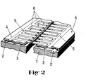
- Figur 2 eine perspektivische Ansicht des Elementes, teilweise im Schnitt.
- Das flüssigkeitsempfindliche Element besteht aus einer rechteckförmigen, flächigen Isolierstoffplatte 1, vorzugsweise aus Hartpapier, auf die zunächst die Anschlußleiterbahnen 2 für die Widerstandsheizschicht 3 z.B. in Siebdrucktechnik aufgebracht sind. Als Material für die Anschlußleiterbahnen 2 wird eine Widerstandspaste, z.B. eine für eine chemische Verkupferung kernkatalysierte Pyropolymerwiderstandspaste, verwendet. Der Widerstandswert der Paste ist von untergeordneter Bedeutung, da die Anschlußleiterbahnen in einem chemischen Bad ohnehin durch eine chemische Metallablagerung verstärkt werden, wobei das Metall niederohmig elektrisch leitend ist.
- Bei der verkupferbaren Pyropolymerwiderstandspaste handelt es sich um eine Paste, die aus einem Bindemittel besteht, dem die leitfähigen Partikel und die Katalysatorsubstanz beigemengt sind. Als Bindemittel können Mischungen aus caprolaktam-blockierten Polyurethan mit Silikonharzen und/oder Acetalharzen und/oder Vinylchlorid-Vinylacetatpolymerisaten und/oder gesättigte Polyester Verwendung finden. Ferner können die Bindemittel ein caprolaktam-blockiertes Addukt des Isoporondiisocyanates und einem hydroxylgruppenhaltigen Oxyesters sein.
- Der Widerstandswert richtet sich nach der Art und der Packungsdichte der Pyropolymere. Dies sind elektrisch leitfähige Teilchen, die mit pyrolytischem Kohlenstoff umhüllt sind. Die Teilchen bestehen aus Aluminiumphosphat, Aluminiumoxid, Siliziumdioxid, Titandioxid, Eisenkarbid, Zinnoxid oder Bleioxid. Als leitfähige Teilchen können auch Ruß, Graphit oder Abmischungen dem Bindemittel beigemengt sein.
- Außerdem sind im Bindemittel noch Katalysatoren vorhanden, die für die chemische Metallabscheidung der Anschlußleiterbahnen wirksam werden. Unter dem Ausdruck "katalytisch" soll ein Stoff oder ein Material verstanden werden, das die Metallabscheidung aus chemisch arbeitenden Bädern bewirkt. Derartige für die chemische Metallabscheidung wirksame Füllstoffe bilden an der Oberfläche und im Porensystem des Bindemittels katalytisch wirksame Zentren, an denen sich eine gut haftende Metallschicht aus einem chemisch arbeitenden Metallisierungsbad aufbauen läßt. Als Katalysatoren werden Metalle oder Metallverbindungen der Kupfer und/oder der Platingruppe eingesetzt. Die Katalysatoren können getrennt von dem mit pyrolytischem Kohlenstoff umhüllten feuerfesten Teilchen dem Bindemittel beigemengt werden. Andererseits können diese mit Kohlenstoff umhüllten Teilchen auch mit den Katalysatoren bekeimt werden. Hierbei kann man beispielsweise so vorgehen, daß das Füllstoffmaterial als Schüttgut in eine Lösung getaucht wird, die Metalle der Kupfergruppe oder der Platingruppe enthält. Hierbei werden an den Füllstoff teilchen Keime von Metallen bzw. Metallverbindungen abgeschieden. Anstelle der Metalle der genannten Gruppen können auch andere Metalle zur Bekeimung des Füllstoffes dienen. Die Auswahl dieser Metalle wird jeweils in Abhängigkeit von der später zu verwendenden Metallabscheidungslösung getroffen. Die Metallverbindungen des Kupfers, wie Kupfer-I-Oxid, sind jedoch ganz besonders als Katalysatoren für die Kupfermetallisierung geeignet. Vorzugsweise wird eine Bekeimung der Füllstoffmaterialien durchgeführt, in dem die Füllstoffteilchen mit einer Kupfer-I-Chlorid-Lösung getränkt werden und das an der Füllstoffteilchenoberfläche absorbierte Kupfer-I-Chlorid durch z.B. NaOH-Einwirkung in das praktisch in Wasser unlösliche Kupfer-I-Oxid umgewandelt wird.
- Nachdem die Anschlußleiterbahnen 2 im chemischen Bad mit Kupfer beschichtet worden sind, wird im nächsten Schritt die Widerstandsheizschicht 3 im Siebdruckverfahren aufgebracht. Diese Schicht besteht ebenfalls aus einer Pyropolymerwiderstandspaste, die im Widerstandswert meist etwas hochohmiger ist als die der Anschlußleiterbahnen 2. Außerdem fehlen in dieser Paste die für die chemische Abscheidung wichtigen Katalysatoren.
- Ober der Widerstandsheizschicht 3 befindet sich eine Isolierschicht 4, in der die Elektroden 5, 6 eingebettet sind. Diese Elektroden bestehen aus zwei Längselektroden 5, die sich am Rand parallel zu den beiden Längsseiten der Isolierstoffplatte 1 erstrecken, und kammförmigen Zinken 6, die abwechselnd von den beiden Längselektroden 5 nach innen verlaufen, ohne sich jedoch zu berühren. Gelangt nun eine elektrisch leitende Flüssigkeit zwischen die Zinken, so wird der zuvor sehr hochohmige Widerstand erniedrigt und diese Erniedrigung kann z.B. zur Anzeige von Regen ausgenutzt werden.
- Es ist leicht ersichtlich, daß die relativ dünne Isolierschicht 4, die sich zwischen der Widerstandsheizschicht 3 und den Elektroden 5, 6 befindet, leichter aufheizbar ist, als die im Vergleich dazu relativ dicke Isolierstoffplatte 1. Das Element erhält dadurch eine kürzere Ansprechzeit. Außerdem ist dies energiesparender, da weniger Energie benötigt wird, um den gleichen Effekt, nämlich Trocknung der glatten Oberfläche des Elementes, zu erzielen.
- Das Aufbringen der Isolierschicht 4 zusammen mit den Elektroden 5, 6 erfolgt mit Hilfe der sogenannten Umkehrlaminiertechnik. Bei dieser Technik geht man zunächst von einem Zwischenträger aus, auf dem die Elektroden im gewünschten Layout, vorzugsweise durch Aufdrucken im Siebdruckverfahren, aufgebracht sind. Danach wird das Gebilde ausgehärtet und mit der beschichteten Seite auf die Isolierstoffplatte 1, die bereits mit der Widerstandsheizschicht versehen ist, auflaminiert, unter Verwendung eines Epoxyharzklebers als Isolierschicht. In einem abschließenden Verfahrensschritt wird der Zwischenträger abgezogen bzw. vollständig abgeätzt. Die Anschlußstellen an den Leiterbahnen bzw. Elektroden für Nieten oder Crampen werden zuvor mittels einer Abdeckung abgedeckt.
- Das Material für die Elektroden 5, 6 besteht aus einer niederohmigen, rußhaltigen Paste. Diese Paste zeigt keine Wanderungserscheinungen bei hoher Feuchtigkeit oder in Anwesenheit von Flüssigkeit. Es kann auch eine niederohmige Paste aus pyrolytisch mit Kohlenstoff beschichteten temperaturbeständigen Teilchen verwendet werden.
- Günstig auf eine kürzere Ansprechzeit wirkt es sich auch aus, daß die Widerstandsheizschicht 3 die Fläche, auf der die Zinken 6 angeordnet sind, ganz überdeckt.
- Bedingt durch die Umkehrlaminiertechnik bzw. die dadurch erzielte Einbettung der Elektroden in die Isolierschicht wird eine glatte Oberfläche erreicht, so daß die Flüssigkeit bei Schrägstellung leicht abfließen kann.
- Das Element kann nicht nur als Regensensor eingesetzt werden, sondern überall da, wo es darauf ankommt, das Vorhandensein von leitenden Flüssigkeiten anzuzeigen.
-
- 1 Isolierstoffplatte
- 2 Anschlußleiterbahnen
- 3 Widerstandsheizschicht
- 4 Isolierschicht
- 5 Längselektroden
- 6 Zinken
Claims (5)
dadurch gekennzeichnet,
daß sich die die Zinken (6) ganz überdeckende Widerstandsheizschicht (3) auf der gleichen Seite der Isolierstoffplatte (1) befindet wie die Elektroden (5, 6) und daß beide nur durch eine im Vergleich zur Isolierstoffplatte (1) dünne Isolierschicht (4) voneinander getrennt sind.
dadurch gekennzeichnet,
daß die zuerst auf die Isolierstoffplatte (1) aufgebrachte Widerstandsheizschicht (3) aus einer Pyropolymerwiderstandspaste besteht.
daß die Anschlußleiterbahnen (2) für die Widerstandsheizschicht (3) aus einer Pyropolymerwiderstandspaste bestehen, der für die chemische Metallabscheidung wirksame Katalysatoren beigemengt sind.
daß die Elektroden (5, 6) in einer Umkehrlaminiertechnik hergestellt sind, so daß die Elektroden in der Isolierschicht (4) derart eingebettet sind, daß eine glatte Oberfläche entsteht.
dadurch gekennzeichnet,
daß die Elektroden (5, 6) aus einer niederohmigen, rußhaltigen Paste bestehen.
Priority Applications (1)
| Application Number | Priority Date | Filing Date | Title |
|---|---|---|---|
| AT83111248T ATE32952T1 (de) | 1982-12-15 | 1983-11-11 | Fluessigkeitsempfindliches element. |
Applications Claiming Priority (2)
| Application Number | Priority Date | Filing Date | Title |
|---|---|---|---|
| DE3246412 | 1982-12-15 | ||
| DE19823246412 DE3246412A1 (de) | 1982-12-15 | 1982-12-15 | Fluessigkeitsempfindliches element |
Publications (3)
| Publication Number | Publication Date |
|---|---|
| EP0111733A2 true EP0111733A2 (de) | 1984-06-27 |
| EP0111733A3 EP0111733A3 (en) | 1985-04-10 |
| EP0111733B1 EP0111733B1 (de) | 1988-03-09 |
Family
ID=6180731
Family Applications (1)
| Application Number | Title | Priority Date | Filing Date |
|---|---|---|---|
| EP83111248A Expired EP0111733B1 (de) | 1982-12-15 | 1983-11-11 | Flüssigkeitsempfindliches Element |
Country Status (3)
| Country | Link |
|---|---|
| EP (1) | EP0111733B1 (de) |
| AT (1) | ATE32952T1 (de) |
| DE (1) | DE3246412A1 (de) |
Cited By (2)
| Publication number | Priority date | Publication date | Assignee | Title |
|---|---|---|---|---|
| EP0356682A3 (de) * | 1988-08-31 | 1991-01-09 | Robert Bosch Gmbh | Feuchtesensor |
| WO2003012419A1 (en) * | 2001-07-06 | 2003-02-13 | Bioett Ab | Moisture sensor |
Families Citing this family (2)
| Publication number | Priority date | Publication date | Assignee | Title |
|---|---|---|---|---|
| DE3916921C1 (de) * | 1989-05-24 | 1990-10-11 | Preh-Werke Gmbh & Co Kg, 8740 Bad Neustadt, De | |
| DK90192D0 (da) * | 1992-07-09 | 1992-07-09 | Rasmussen Kann Ind As | Elektrisk regnfoeler og fremgangsmaade til fremstilling af et foelerelement dertil |
Family Cites Families (10)
| Publication number | Priority date | Publication date | Assignee | Title |
|---|---|---|---|---|
| JPS5152005A (ja) * | 1974-09-12 | 1976-05-08 | Uop Inc | Denkiteikotaiinki |
| JPS51151176A (en) * | 1975-06-20 | 1976-12-25 | Asahi Glass Co Ltd | Dew condensation sensor |
| US4011538A (en) * | 1976-01-30 | 1977-03-08 | Illinois Tool Works Inc. | Fluid sensor |
| AT368811B (de) * | 1978-07-12 | 1982-11-10 | Siemens Ag Oesterreich | Feuchtigkeitsmesseinrichtung |
| DE2938434C2 (de) * | 1979-09-22 | 1981-07-09 | Fraunhofer-Gesellschaft zur Förderung der angewandten Forschung e.V., 8000 München | Kapazitiver Feuchtigkeitsfühler und Verfahren zur Herstellung des Fühlers |
| DE3045617A1 (de) * | 1979-12-03 | 1981-08-20 | Tokyo Cosmos Electric Co. Ltd.,, Hachioji, Tokyo | Feuchtigkeitsempfindlicher widerstand |
| DE3024297C2 (de) * | 1980-06-27 | 1985-08-14 | Endress U. Hauser Gmbh U. Co, 7867 Maulburg | Kapazitiver Feuchtigkeitsfühler und Verfahren zum Herstellen seiner feuchtigkeitsempfindlichen Schicht |
| DE8121939U1 (de) * | 1981-07-25 | 1982-01-14 | Kernforschungsanlage Jülich GmbH, 5170 Jülich | Regenfuehler fuer einen regensammler |
| DE3176700D1 (en) * | 1981-09-30 | 1988-05-05 | Mitsubishi Electric Corp | Humidity sensor |
| US4520341A (en) * | 1981-12-08 | 1985-05-28 | Sharp Kabushiki Kaisha | Moisture responsive element with crosslinked organic membrane and protective layering |
-
1982
- 1982-12-15 DE DE19823246412 patent/DE3246412A1/de active Granted
-
1983
- 1983-11-11 AT AT83111248T patent/ATE32952T1/de not_active IP Right Cessation
- 1983-11-11 EP EP83111248A patent/EP0111733B1/de not_active Expired
Cited By (3)
| Publication number | Priority date | Publication date | Assignee | Title |
|---|---|---|---|---|
| EP0356682A3 (de) * | 1988-08-31 | 1991-01-09 | Robert Bosch Gmbh | Feuchtesensor |
| WO2003012419A1 (en) * | 2001-07-06 | 2003-02-13 | Bioett Ab | Moisture sensor |
| US7071830B2 (en) | 2001-07-06 | 2006-07-04 | Bioett Ab | Moisture sensor |
Also Published As
| Publication number | Publication date |
|---|---|
| EP0111733A3 (en) | 1985-04-10 |
| DE3246412C2 (de) | 1988-03-17 |
| ATE32952T1 (de) | 1988-03-15 |
| EP0111733B1 (de) | 1988-03-09 |
| DE3246412A1 (de) | 1984-06-20 |
Similar Documents
| Publication | Publication Date | Title |
|---|---|---|
| EP1623217A1 (de) | Sensor zur detektion von teilchen | |
| DE2235783C2 (de) | Metalloxid-Varistorelement | |
| EP0043001B1 (de) | Feuchtigkeitsfühler und Verfahren zu seiner Herstellung | |
| WO1998031991A1 (de) | Füllstandsgeber | |
| DE4036109C2 (de) | Widerstandstemperaturfühler | |
| DE69201930T2 (de) | Anschluss von Verglasungen mit einer elektrisch leitfähigen Schicht. | |
| DE2824609C2 (de) | Vorrichtung zur Feuchtigkeitsmessung durch elektrostatische Kapazitätsänderung | |
| WO1995006320A1 (de) | Photovoltaische zelle mit eingebetteten leiterbahnen | |
| EP0111733B1 (de) | Flüssigkeitsempfindliches Element | |
| WO2016142080A1 (de) | Herstellungsverfahren für einen gassensor und entsprechender gassensor | |
| EP2188841B1 (de) | Elektronisches bauelement, verfahren zu seiner herstellung und seine verwendung | |
| EP0280150B1 (de) | Raumheizelement, bestehend aus einem mit einer elektrischen Widerstandsbeschichtung versehenen keramischen Formkörper, insbesondere in Form einer keramischen Platte | |
| DE19519099C1 (de) | Resistiver Feuchtesensor | |
| DE2853134C2 (de) | Keramikvaristor | |
| EP0243602B1 (de) | Elektrisches Bauelement mit hoher Festigkeit bei Beanspruchung durch Temperaturwechsel und durch Stossströme, insbesondere ein Varistor | |
| WO2015104015A2 (de) | Sensorelement zur bestimmung von dehnungen | |
| DE3410578A1 (de) | Duennfilm-feuchtigkeitsmessfuehler | |
| DE8235238U1 (de) | Fluessigkeitsempfindliches element | |
| DE1765097C3 (de) | Spannungsabhaengiger Widerstand aus einer gesinterten Scheibe aus Zinkoxid | |
| WO2010130370A1 (de) | Fotolithographisch strukturierter dickschichtsensor | |
| DE1018171B (de) | Bildschirm mit einander zugeordneten photoempfindlichen und elektrolumineszierenden Elementen | |
| DE3050770C2 (de) | Verfahren zur Herstellung eines Varistors | |
| DE3416945A1 (de) | Feuchtigkeitssensor und verfahren zu seiner herstellung | |
| DE3905444C2 (de) | Keramischer Kondensator und Verfahren zu dessen Herstellung | |
| DE3900787A1 (de) | Verfahren zur herstellung eines keramischen elektrischen bauelementes |
Legal Events
| Date | Code | Title | Description |
|---|---|---|---|
| PUAI | Public reference made under article 153(3) epc to a published international application that has entered the european phase |
Free format text: ORIGINAL CODE: 0009012 |
|
| AK | Designated contracting states |
Designated state(s): AT BE CH FR GB IT LI NL SE |
|
| PUAL | Search report despatched |
Free format text: ORIGINAL CODE: 0009013 |
|
| AK | Designated contracting states |
Designated state(s): AT BE CH FR GB IT LI NL SE |
|
| 17P | Request for examination filed |
Effective date: 19850430 |
|
| 17Q | First examination report despatched |
Effective date: 19860704 |
|
| ITF | It: translation for a ep patent filed | ||
| GRAA | (expected) grant |
Free format text: ORIGINAL CODE: 0009210 |
|
| AK | Designated contracting states |
Kind code of ref document: B1 Designated state(s): AT BE CH FR GB IT LI NL SE |
|
| REF | Corresponds to: |
Ref document number: 32952 Country of ref document: AT Date of ref document: 19880315 Kind code of ref document: T |
|
| GBT | Gb: translation of ep patent filed (gb section 77(6)(a)/1977) | ||
| ET | Fr: translation filed | ||
| PLBE | No opposition filed within time limit |
Free format text: ORIGINAL CODE: 0009261 |
|
| STAA | Information on the status of an ep patent application or granted ep patent |
Free format text: STATUS: NO OPPOSITION FILED WITHIN TIME LIMIT |
|
| 26N | No opposition filed | ||
| PGFP | Annual fee paid to national office [announced via postgrant information from national office to epo] |
Ref country code: AT Payment date: 19891102 Year of fee payment: 7 |
|
| PGFP | Annual fee paid to national office [announced via postgrant information from national office to epo] |
Ref country code: BE Payment date: 19891114 Year of fee payment: 7 |
|
| PGFP | Annual fee paid to national office [announced via postgrant information from national office to epo] |
Ref country code: SE Payment date: 19891116 Year of fee payment: 7 |
|
| PGFP | Annual fee paid to national office [announced via postgrant information from national office to epo] |
Ref country code: NL Payment date: 19891130 Year of fee payment: 7 |
|
| PG25 | Lapsed in a contracting state [announced via postgrant information from national office to epo] |
Ref country code: AT Effective date: 19901111 |
|
| PG25 | Lapsed in a contracting state [announced via postgrant information from national office to epo] |
Ref country code: SE Effective date: 19901112 |
|
| PG25 | Lapsed in a contracting state [announced via postgrant information from national office to epo] |
Ref country code: BE Effective date: 19901130 |
|
| BERE | Be: lapsed |
Owner name: PREH ELEKTROFEINMECHANISCHE WERKE JAKOB PREH NACH Effective date: 19901130 |
|
| PG25 | Lapsed in a contracting state [announced via postgrant information from national office to epo] |
Ref country code: NL Effective date: 19910601 |
|
| NLV4 | Nl: lapsed or anulled due to non-payment of the annual fee | ||
| ITTA | It: last paid annual fee | ||
| PGFP | Annual fee paid to national office [announced via postgrant information from national office to epo] |
Ref country code: GB Payment date: 19941024 Year of fee payment: 12 |
|
| PGFP | Annual fee paid to national office [announced via postgrant information from national office to epo] |
Ref country code: FR Payment date: 19941027 Year of fee payment: 12 |
|
| PGFP | Annual fee paid to national office [announced via postgrant information from national office to epo] |
Ref country code: CH Payment date: 19950120 Year of fee payment: 12 |
|
| EUG | Se: european patent has lapsed |
Ref document number: 83111248.7 Effective date: 19910705 |
|
| PG25 | Lapsed in a contracting state [announced via postgrant information from national office to epo] |
Ref country code: GB Effective date: 19951111 |
|
| PG25 | Lapsed in a contracting state [announced via postgrant information from national office to epo] |
Ref country code: LI Effective date: 19951130 Ref country code: CH Effective date: 19951130 |
|
| GBPC | Gb: european patent ceased through non-payment of renewal fee |
Effective date: 19951111 |
|
| REG | Reference to a national code |
Ref country code: CH Ref legal event code: PL |
|
| PG25 | Lapsed in a contracting state [announced via postgrant information from national office to epo] |
Ref country code: FR Effective date: 19960731 |
|
| REG | Reference to a national code |
Ref country code: FR Ref legal event code: ST |