EP0111754A1 - Appareil respiratoire pour la ventilation sur pression - Google Patents
Appareil respiratoire pour la ventilation sur pression Download PDFInfo
- Publication number
- EP0111754A1 EP0111754A1 EP83111402A EP83111402A EP0111754A1 EP 0111754 A1 EP0111754 A1 EP 0111754A1 EP 83111402 A EP83111402 A EP 83111402A EP 83111402 A EP83111402 A EP 83111402A EP 0111754 A1 EP0111754 A1 EP 0111754A1
- Authority
- EP
- European Patent Office
- Prior art keywords
- breathing
- mask
- locking
- control membrane
- respirator
- Prior art date
- Legal status (The legal status is an assumption and is not a legal conclusion. Google has not performed a legal analysis and makes no representation as to the accuracy of the status listed.)
- Granted
Links
- 230000000241 respiratory effect Effects 0.000 title claims description 11
- 238000009423 ventilation Methods 0.000 title 1
- 230000029058 respiratory gaseous exchange Effects 0.000 claims abstract description 62
- 239000012528 membrane Substances 0.000 claims abstract description 30
- 230000000903 blocking effect Effects 0.000 claims abstract description 6
- 210000000056 organ Anatomy 0.000 claims description 2
- 210000004072 lung Anatomy 0.000 abstract description 13
- 230000009471 action Effects 0.000 abstract description 3
- 230000001960 triggered effect Effects 0.000 abstract description 2
- 230000000149 penetrating effect Effects 0.000 abstract 1
- 210000004379 membrane Anatomy 0.000 description 26
- 125000006850 spacer group Chemical group 0.000 description 4
- 239000003570 air Substances 0.000 description 3
- 230000006835 compression Effects 0.000 description 2
- 238000007906 compression Methods 0.000 description 2
- 230000005484 gravity Effects 0.000 description 2
- 230000009467 reduction Effects 0.000 description 2
- 238000007789 sealing Methods 0.000 description 2
- 241001295925 Gegenes Species 0.000 description 1
- 239000012080 ambient air Substances 0.000 description 1
- 230000008859 change Effects 0.000 description 1
- 239000003638 chemical reducing agent Substances 0.000 description 1
- 238000010276 construction Methods 0.000 description 1
- 230000007423 decrease Effects 0.000 description 1
- 230000000694 effects Effects 0.000 description 1
- 230000009191 jumping Effects 0.000 description 1
- 230000007246 mechanism Effects 0.000 description 1
- 230000035939 shock Effects 0.000 description 1
- 230000007704 transition Effects 0.000 description 1
Images
Classifications
-
- A—HUMAN NECESSITIES
- A62—LIFE-SAVING; FIRE-FIGHTING
- A62B—DEVICES, APPARATUS OR METHODS FOR LIFE-SAVING
- A62B9/00—Component parts for respiratory or breathing apparatus
- A62B9/02—Valves
- A62B9/022—Breathing demand regulators
-
- Y—GENERAL TAGGING OF NEW TECHNOLOGICAL DEVELOPMENTS; GENERAL TAGGING OF CROSS-SECTIONAL TECHNOLOGIES SPANNING OVER SEVERAL SECTIONS OF THE IPC; TECHNICAL SUBJECTS COVERED BY FORMER USPC CROSS-REFERENCE ART COLLECTIONS [XRACs] AND DIGESTS
- Y10—TECHNICAL SUBJECTS COVERED BY FORMER USPC
- Y10S—TECHNICAL SUBJECTS COVERED BY FORMER USPC CROSS-REFERENCE ART COLLECTIONS [XRACs] AND DIGESTS
- Y10S137/00—Fluid handling
- Y10S137/908—Respirator control
-
- Y—GENERAL TAGGING OF NEW TECHNOLOGICAL DEVELOPMENTS; GENERAL TAGGING OF CROSS-SECTIONAL TECHNOLOGIES SPANNING OVER SEVERAL SECTIONS OF THE IPC; TECHNICAL SUBJECTS COVERED BY FORMER USPC CROSS-REFERENCE ART COLLECTIONS [XRACs] AND DIGESTS
- Y10—TECHNICAL SUBJECTS COVERED BY FORMER USPC
- Y10T—TECHNICAL SUBJECTS COVERED BY FORMER US CLASSIFICATION
- Y10T137/00—Fluid handling
- Y10T137/7722—Line condition change responsive valves
- Y10T137/7781—With separate connected fluid reactor surface
- Y10T137/7782—With manual or external control for line valve
Definitions
- the invention relates to a breathing mask with excess pressure in the interior of the mask, in accordance with the preamble of patent claim 1.
- a known respirator mask is equipped with a lung-controlled valve, with which excess pressure is generated and maintained in the interior of the mask.
- the valve comprises, in a valve housing between a breathing chamber opening out in front of the user's respiratory organs and an outer chamber connected to the external atmosphere, a pressure chamber connected to both chambers via a valve.
- a pressure chamber connected to both chambers via a valve.
- an excess pressure is generated in the breathing chamber and thus in the mask interior both during inhalation and during exhalation.
- a wall part of the pressure chamber is movably connected to the inner wall of the valve housing via a control membrane.
- An inlet valve of the breathing mask for breathing gas is actuated via an actuating device via the respiratory pressure movement, the pressure chamber.
- a switchable blocking device enables the breathing gas supply to be interrupted when the mask is removed.
- the locking device consists of a shaft rotatably mounted in the breathing chamber. One end is guided in an airtight guide bushing through the wall of the breathing chamber to the outside and there is provided with a radial actuating lever. At this the shaft can be swiveled between two end positions. In one end position, the locked position, a resilient tongue of the actuating lever engages in a recess in the wall of the breathing chamber.
- the shaft has a wire bracket inside. The wire bracket touches the lever arm of the inlet valve in the locked position and brings it into the closed position.
- a leg spring pushes the wire bracket, which can be pivoted with the shaft, into the other end position, the release position, in which it rests against the inner wall of the breathing chamber and allows the lever arm to move freely.
- the actuating lever to be operated beforehand has been locked into the locked position, thereby interrupting the breathing gas supply.
- the first breath is automatically activated.
- a force must be generated by the suction of the inhalation acting on the membrane on the lever arm, which is sufficient to force the locking device out of the locking position.
- the leg spring then brings the locking device into the release position.
- a known lung-controlled compressed air breathing apparatus with overpressure in the respiratory mask contains in its lung-controlled valve a control membrane and a metering valve that can be opened from the pre-pressure.
- the control membrane from which the ambient air acts, limits the inside of a control room that is under the internal pressure of the respirator.
- the control membrane is connected to the metering valve via a rocker arm and closes it against the force of the inflowing compressed air as soon as a certain overpressure in the control chamber is enough.
- a spacer is movable longitudinally and tightly outwards from the control chamber through its wall opposite the control membrane. It ends in the control room in a stop plate which is loaded by a compression spring in the direction of the control membrane.
- an eccentric switch lever is rotatably attached, which is supported against the wall of the control room.
- the stop plate lies against the rocker arm.
- the force of the compression spring then closes the metering valve even when the respirator mask is removed and there is no excess pressure in the control room.
- the switch position with the eccentric cocked, the release position the stop plate is held at a distance from the rocker arm and the full movement of the control membrane is released.
- the transition to the release position takes place automatically when the control membrane with the rocker arm moves the spacer bolt outwards against the spring force under the first breath.
- the switch lever relieved in this way is oriented towards gravity in such a way that it then tilts into the release position under the weight of its grip part. Switching to the locked position must be done manually.
- Another compressed gas breathing apparatus with an overpressure in the breathing mask is known, in which the breathing mask is connected via a lung-controlled valve via a line to the outlet of a pressure reducer and is supplied with breathing gas from there.
- a control membrane is acted upon on its outer side by the ambient pressure and a spring.
- the inner side is burdened by the pressure inside the mask.
- One arm of a pivotally held rocker arm bears against this side, while the other arm is connected to the closing element of the valve, a closing piston.
- the closing piston contains a transverse opening, with which it connects the respiratory gas line to the inside of the respirator mask or closes the line in the appropriate position.
- This well-known compressed gas breathing apparatus with overpressure in the breathing mask is suitable for normal requirements. Too large suddenly required amounts of breathing gas and also dynamic stresses from e.g. Running and jumping cause the locking piston to make jerky movements and thus to uncontrolled breathing gas conditions in the mask interior.
- the object of the invention is to find a lung-controlled valve for respiratory masks that are used together with compressed gas respirators and in which excess pressure must be maintained, which ensures the necessary higher breathing air requirement in the case of spontaneously changing loads on the wearer, such as suddenly occurring heavy work which prevents the outflow of breathing gas when the breathing gas storage tank valve is open when the breathing mask is not in place, but the breathing apparatus can nevertheless be ventilated immediately after the breathing mask is put on.
- This object is achieved in a generic respiratory mask by the characterizing features of claim 1.
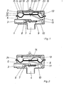
- the lung-controlled valve has a valve housing 1 with a breathing gas connector 3 for the supply of
- valve housing 1 is separated from the cover 2 by a control membrane 5, forming an outer chamber 24 above the cover 2 and a breathing chamber 6 below, the pressure of which corresponds to the internal pressure of the respirator.
- the breathing gas nozzle 3 is separated from the breathing chamber 6 by a lung-controlled inlet valve 7, 8 for the breathing gas, consisting of valve seat 7 and valve body 8.
- the valve body 8 is biased in the closing direction by a closing spring 9 and is in contact with the control membrane 5 via an actuating device.
- a push rod 10 is connected to the shorter lever arm of a single-lever control lever 11.
- the control lever 11 is mounted in the valve housing 1 and bears against the control membrane 5 with its longer lever arm.
- the control membrane 5 has a cup-shaped holding collar 12 on the outside.
- the longer lever of a one-armed overpressure lever 13 bears here. This is mounted in the cover 2 and is biased against the control diaphragm 5 by a semi-circular spring 14 via its shorter lever.
- the pressure lever 13 opposite the spring 14 is held in a bearing 15 in the cover 2.
- the overpressure lever 13 has a locking cam 16.
- the locking slide 17 can be moved via a handle 19 which is guided through a slot 20 to the outside.
- An escapement spring 21 ensures speedy gear.
- the cover 2 On both sides of the locking lug 18 of the locking slide 17, the cover 2 carries a system 22 outside the retaining collar 12.
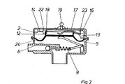
- the inlet valve 7, 8 must remain closed.
- the lung-controlled valve also enables a blocking position.
- the locking slide 17 is moved by hand on its handle 19 to the right. Its pushing end 23 lifts the overpressure lever 13 against the force of the spring 14 via the locking cams 16 and relaxes the control diaphragm 5. It rises because the relief lever 13 relieves it under the action of the closing spring 9.
- the retaining collar 12 enters the gap formed between the systems 22 of the cover 2 and the locking lug 18 of the locking slide 17.
Landscapes
- Health & Medical Sciences (AREA)
- Pulmonology (AREA)
- General Health & Medical Sciences (AREA)
- Business, Economics & Management (AREA)
- Emergency Management (AREA)
- Respiratory Apparatuses And Protective Means (AREA)
Applications Claiming Priority (2)
| Application Number | Priority Date | Filing Date | Title |
|---|---|---|---|
| DE3245717A DE3245717C1 (de) | 1982-12-10 | 1982-12-10 | Lungengesteuertes Ventil fuer den UEberdruckbetrieb im Maskeninnenraum |
| DE3245717 | 1982-12-10 |
Publications (2)
| Publication Number | Publication Date |
|---|---|
| EP0111754A1 true EP0111754A1 (fr) | 1984-06-27 |
| EP0111754B1 EP0111754B1 (fr) | 1987-05-06 |
Family
ID=6180305
Family Applications (1)
| Application Number | Title | Priority Date | Filing Date |
|---|---|---|---|
| EP83111402A Expired EP0111754B1 (fr) | 1982-12-10 | 1983-11-15 | Appareil respiratoire pour la ventilation sur pression |
Country Status (4)
| Country | Link |
|---|---|
| US (1) | US4572176A (fr) |
| EP (1) | EP0111754B1 (fr) |
| JP (1) | JPS59115055A (fr) |
| DE (1) | DE3245717C1 (fr) |
Cited By (2)
| Publication number | Priority date | Publication date | Assignee | Title |
|---|---|---|---|---|
| EP0371209A3 (fr) * | 1988-11-28 | 1991-12-18 | Auergesellschaft Gmbh | Clapet contrôlé par action pulmonaire |
| EP0442273A3 (en) * | 1990-02-16 | 1992-04-22 | Space Biospheres Venture | Pressure balancing a closed ecological system |
Families Citing this family (19)
| Publication number | Priority date | Publication date | Assignee | Title |
|---|---|---|---|---|
| DE3401383A1 (de) * | 1984-01-17 | 1985-07-25 | Drägerwerk AG, 2400 Lübeck | Atemschutzmaske mit ueberdruck im maskeninnenraum |
| US4683881A (en) * | 1985-10-30 | 1987-08-04 | U.S.D. Corp. | Breathing regulator mouthpiece |
| DE3539668A1 (de) * | 1985-11-08 | 1987-05-21 | Draegerwerk Ag | Lungengesteuertes membranventil fuer atemschutzmasken |
| FR2644750A1 (fr) * | 1989-03-21 | 1990-09-28 | Spirotech Ind Commerc | Dispositif d'alimentation en gaz respiratoire pour plongeur |
| JPH06191481A (ja) * | 1992-12-22 | 1994-07-12 | Zexel Corp | 半閉鎖式呼吸装置のマウスピース |
| GB9301959D0 (en) * | 1993-02-01 | 1993-03-17 | Sabre Safety Ltd | A valve for use in breathing apparatus |
| GB2315116B (en) * | 1993-09-22 | 1998-03-25 | Racal Health & Safety Ltd | Valves |
| GB9319580D0 (en) * | 1993-09-22 | 1993-11-10 | Racal Health & Safety Ltd | Valves |
| US5551474A (en) * | 1995-06-20 | 1996-09-03 | Chuang; Rung-Chao | Gas flow direct pressure regulator |
| GB9619459D0 (en) * | 1996-09-18 | 1996-10-30 | Jackson Peter J | Breathing apparatus |
| FR2781381B1 (fr) * | 1998-07-24 | 2000-09-29 | Intertechnique Sa | Regulateur a la demande pour systeme respiratoire |
| ITGE20010028A1 (it) * | 2001-03-23 | 2002-09-23 | Htm Sport Spa | Erogatore per apparecchi respiratori subacquei. |
| DE102004052173B3 (de) * | 2004-10-27 | 2006-01-12 | Dräger Safety AG & Co. KGaA | Atemschutzmaske für Normaldruck- und Überdruckbetrieb |
| GB0509369D0 (en) * | 2005-05-07 | 2005-06-15 | Foss Nicholas J | A breathing apparatus demand valve |
| JP5528899B2 (ja) * | 2010-04-28 | 2014-06-25 | 興研株式会社 | 供給弁 |
| US9278235B1 (en) * | 2012-03-12 | 2016-03-08 | Lynn H. Phillips | Adaptive demand oxygen delivery system |
| US11077323B2 (en) * | 2015-12-30 | 2021-08-03 | Scott Technologies, Inc. | Respirator mask with air-saver switch |
| DE102020000335A1 (de) * | 2020-01-21 | 2021-07-22 | Drägerwerk AG & Co. KGaA | Ventil-Anordnung mit Absperreinheit und Verfahren für ein Beatmungsgerät |
| EP4389233A1 (fr) * | 2022-12-22 | 2024-06-26 | Dräger Safety AG & Co. KGaA | Régulateur de la demande pulmonaire |
Citations (2)
| Publication number | Priority date | Publication date | Assignee | Title |
|---|---|---|---|---|
| GB1019986A (en) * | 1962-12-21 | 1966-02-09 | Robertshaw Controls Co | Breathing demand regulator |
| EP0021803A1 (fr) * | 1979-06-21 | 1981-01-07 | Chubb Panorama Limited | Soupapes et appareil respiratoire comportant de telles soupapes |
Family Cites Families (6)
| Publication number | Priority date | Publication date | Assignee | Title |
|---|---|---|---|---|
| US986344A (en) * | 1910-07-14 | 1911-03-07 | Reliance Engineering & Mfg Company Of Chicago | Automatic gas-regulator. |
| US1824072A (en) * | 1930-09-22 | 1931-09-22 | Chipley D Bullard | Automatic safety valve |
| US2406888A (en) * | 1944-06-06 | 1946-09-03 | Scott Aviation Corp | Breathing apparatus |
| US3180356A (en) * | 1963-01-07 | 1965-04-27 | American Radiator & Standard | Combination pressure regulator and shut-off valve |
| DE2620170A1 (de) * | 1976-05-07 | 1977-11-17 | Draegerwerk Ag | Lungengesteuertes pressluftatemgeraet mit ueberdruck in der atemschutzmaske |
| SE428760B (sv) * | 1979-10-09 | 1983-07-25 | Aga Ab | Andningsmask |
-
1982
- 1982-12-10 DE DE3245717A patent/DE3245717C1/de not_active Expired
-
1983
- 1983-10-19 US US06/543,317 patent/US4572176A/en not_active Expired - Fee Related
- 1983-11-15 EP EP83111402A patent/EP0111754B1/fr not_active Expired
- 1983-12-09 JP JP58231599A patent/JPS59115055A/ja active Granted
Patent Citations (2)
| Publication number | Priority date | Publication date | Assignee | Title |
|---|---|---|---|---|
| GB1019986A (en) * | 1962-12-21 | 1966-02-09 | Robertshaw Controls Co | Breathing demand regulator |
| EP0021803A1 (fr) * | 1979-06-21 | 1981-01-07 | Chubb Panorama Limited | Soupapes et appareil respiratoire comportant de telles soupapes |
Cited By (4)
| Publication number | Priority date | Publication date | Assignee | Title |
|---|---|---|---|---|
| EP0371209A3 (fr) * | 1988-11-28 | 1991-12-18 | Auergesellschaft Gmbh | Clapet contrôlé par action pulmonaire |
| EP0442273A3 (en) * | 1990-02-16 | 1992-04-22 | Space Biospheres Venture | Pressure balancing a closed ecological system |
| US5279081A (en) * | 1990-02-16 | 1994-01-18 | Space Biospheres Ventures | Pressure balancing a closed ecological system |
| US5377458A (en) * | 1990-02-16 | 1995-01-03 | Decisions Team, Inc. | Pressure balancing a closed ecological system |
Also Published As
| Publication number | Publication date |
|---|---|
| JPH0150419B2 (fr) | 1989-10-30 |
| US4572176A (en) | 1986-02-25 |
| DE3245717C1 (de) | 1984-06-07 |
| EP0111754B1 (fr) | 1987-05-06 |
| JPS59115055A (ja) | 1984-07-03 |
Similar Documents
| Publication | Publication Date | Title |
|---|---|---|
| EP0111754B1 (fr) | Appareil respiratoire pour la ventilation sur pression | |
| DE3015760C2 (de) | Lungengesteuertes Druckgas-Atemschutzgerät mit Überdruck in der Atemschutzmaske | |
| DE3229240C2 (de) | Für Überdruckbetrieb geeignetes Atemschutzgerät | |
| DE2541303C3 (de) | Handbetätigter Lungenventilationsapparat mit einer selbst ausweitenden Blase | |
| DE2423289C3 (fr) | ||
| DE1910979A1 (de) | Ventilvorrichtung,vor allem zur Verwendung in Narkosegaszufuhrsystemen | |
| CH624013A5 (fr) | ||
| DE3401383A1 (de) | Atemschutzmaske mit ueberdruck im maskeninnenraum | |
| DE3004594A1 (de) | Warnsignalvorrichtung fuer atemschutzgeraete | |
| DE3750565T2 (de) | Lungenautomat mit Vorsteuerventil. | |
| DE1491737B1 (de) | Druckentlastungsventil zur Verwendung in Beatmungsapparaten | |
| DE2646338C3 (de) | Lungengesteuertes Membranventil für Druckgasatemgeräte | |
| DE1286910B (de) | Lungengesteuerte Atemgaszufuehrungsvorrichtung | |
| DE2620170A1 (de) | Lungengesteuertes pressluftatemgeraet mit ueberdruck in der atemschutzmaske | |
| DE1931903A1 (de) | Ventilationsvorrichtung | |
| DE102012214860B3 (de) | Atemschutzgerät | |
| DE1491698C3 (de) | Beatmungs- oder Narkosebeatmungsgerät | |
| DE69515920T2 (de) | Maske für Atmungsgerät zum Versorgung mit druck- bzw. druckloser Luft | |
| DE102005058401B3 (de) | Lungenautomat für Pressluftatemgeräte | |
| DE3137530A1 (de) | Tuerbetaetigungseinrichtung | |
| DE1063904B (de) | Schnell wirkende Vorrichtung zur Betaetigung eines Ventils | |
| EP0070405A1 (fr) | Accélérateur pour valves-pilotes, particulièrement pour valves pilotes triples de freins à air comprimé pour véhicules ferroviaires | |
| DE2203453A1 (de) | Warnvorrichtung fuer beatmungsgeraete (respiratoren) | |
| DE1491633C (de) | Beatmungsgerät | |
| AT234533B (de) | Druckregler mit Reifenfüllanschluß |
Legal Events
| Date | Code | Title | Description |
|---|---|---|---|
| PUAI | Public reference made under article 153(3) epc to a published international application that has entered the european phase |
Free format text: ORIGINAL CODE: 0009012 |
|
| 17P | Request for examination filed |
Effective date: 19831128 |
|
| AK | Designated contracting states |
Designated state(s): FR GB NL SE |
|
| GRAA | (expected) grant |
Free format text: ORIGINAL CODE: 0009210 |
|
| AK | Designated contracting states |
Kind code of ref document: B1 Designated state(s): FR GB NL SE |
|
| ET | Fr: translation filed | ||
| PLBE | No opposition filed within time limit |
Free format text: ORIGINAL CODE: 0009261 |
|
| STAA | Information on the status of an ep patent application or granted ep patent |
Free format text: STATUS: NO OPPOSITION FILED WITHIN TIME LIMIT |
|
| 26N | No opposition filed | ||
| PGFP | Annual fee paid to national office [announced via postgrant information from national office to epo] |
Ref country code: FR Payment date: 19891013 Year of fee payment: 7 |
|
| PGFP | Annual fee paid to national office [announced via postgrant information from national office to epo] |
Ref country code: GB Payment date: 19891031 Year of fee payment: 7 |
|
| PG25 | Lapsed in a contracting state [announced via postgrant information from national office to epo] |
Ref country code: SE Effective date: 19891116 |
|
| PGFP | Annual fee paid to national office [announced via postgrant information from national office to epo] |
Ref country code: NL Payment date: 19891130 Year of fee payment: 7 |
|
| PG25 | Lapsed in a contracting state [announced via postgrant information from national office to epo] |
Ref country code: GB Effective date: 19901115 |
|
| PG25 | Lapsed in a contracting state [announced via postgrant information from national office to epo] |
Ref country code: NL Effective date: 19910601 |
|
| GBPC | Gb: european patent ceased through non-payment of renewal fee | ||
| NLV4 | Nl: lapsed or anulled due to non-payment of the annual fee | ||
| PG25 | Lapsed in a contracting state [announced via postgrant information from national office to epo] |
Ref country code: FR Effective date: 19910731 |
|
| REG | Reference to a national code |
Ref country code: FR Ref legal event code: ST |
|
| EUG | Se: european patent has lapsed |
Ref document number: 83111402.0 Effective date: 19900705 |