EP0111925A2 - Schraubenförmig gewickelter, warmschrumpfbarer Gegenstand, Verfahren und Vorrichtung zu seiner Herstellung und Verfahren und Vorrichtung zum Anbringen desselben an einem Behälter - Google Patents
Schraubenförmig gewickelter, warmschrumpfbarer Gegenstand, Verfahren und Vorrichtung zu seiner Herstellung und Verfahren und Vorrichtung zum Anbringen desselben an einem Behälter Download PDFInfo
- Publication number
- EP0111925A2 EP0111925A2 EP83112835A EP83112835A EP0111925A2 EP 0111925 A2 EP0111925 A2 EP 0111925A2 EP 83112835 A EP83112835 A EP 83112835A EP 83112835 A EP83112835 A EP 83112835A EP 0111925 A2 EP0111925 A2 EP 0111925A2
- Authority
- EP
- European Patent Office
- Prior art keywords
- container
- containers
- heat
- tube
- mandrel
- Prior art date
- Legal status (The legal status is an assumption and is not a legal conclusion. Google has not performed a legal analysis and makes no representation as to the accuracy of the status listed.)
- Withdrawn
Links
Images



Classifications
-
- B—PERFORMING OPERATIONS; TRANSPORTING
- B29—WORKING OF PLASTICS; WORKING OF SUBSTANCES IN A PLASTIC STATE IN GENERAL
- B29C—SHAPING OR JOINING OF PLASTICS; SHAPING OF MATERIAL IN A PLASTIC STATE, NOT OTHERWISE PROVIDED FOR; AFTER-TREATMENT OF THE SHAPED PRODUCTS, e.g. REPAIRING
- B29C65/00—Joining or sealing of preformed parts, e.g. welding of plastics materials; Apparatus therefor
- B29C65/78—Means for handling the parts to be joined, e.g. for making containers or hollow articles, e.g. means for handling sheets, plates, web-like materials, tubular articles, hollow articles or elements to be joined therewith; Means for discharging the joined articles from the joining apparatus
- B29C65/7841—Holding or clamping means for handling purposes
- B29C65/7847—Holding or clamping means for handling purposes using vacuum to hold at least one of the parts to be joined
-
- B—PERFORMING OPERATIONS; TRANSPORTING
- B26—HAND CUTTING TOOLS; CUTTING; SEVERING
- B26D—CUTTING; DETAILS COMMON TO MACHINES FOR PERFORATING, PUNCHING, CUTTING-OUT, STAMPING-OUT OR SEVERING
- B26D3/00—Cutting work characterised by the nature of the cut made; Apparatus therefor
- B26D3/16—Cutting rods or tubes transversely
-
- B—PERFORMING OPERATIONS; TRANSPORTING
- B26—HAND CUTTING TOOLS; CUTTING; SEVERING
- B26D—CUTTING; DETAILS COMMON TO MACHINES FOR PERFORATING, PUNCHING, CUTTING-OUT, STAMPING-OUT OR SEVERING
- B26D3/00—Cutting work characterised by the nature of the cut made; Apparatus therefor
- B26D3/16—Cutting rods or tubes transversely
- B26D3/163—Cutting tubes from the inside
-
- B—PERFORMING OPERATIONS; TRANSPORTING
- B26—HAND CUTTING TOOLS; CUTTING; SEVERING
- B26D—CUTTING; DETAILS COMMON TO MACHINES FOR PERFORATING, PUNCHING, CUTTING-OUT, STAMPING-OUT OR SEVERING
- B26D3/00—Cutting work characterised by the nature of the cut made; Apparatus therefor
- B26D3/16—Cutting rods or tubes transversely
- B26D3/164—Cutting rods or tubes transversely characterised by means for supporting the tube from the inside
-
- B—PERFORMING OPERATIONS; TRANSPORTING
- B26—HAND CUTTING TOOLS; CUTTING; SEVERING
- B26D—CUTTING; DETAILS COMMON TO MACHINES FOR PERFORATING, PUNCHING, CUTTING-OUT, STAMPING-OUT OR SEVERING
- B26D3/00—Cutting work characterised by the nature of the cut made; Apparatus therefor
- B26D3/16—Cutting rods or tubes transversely
- B26D3/166—Trimming tube-ends
-
- B—PERFORMING OPERATIONS; TRANSPORTING
- B29—WORKING OF PLASTICS; WORKING OF SUBSTANCES IN A PLASTIC STATE IN GENERAL
- B29C—SHAPING OR JOINING OF PLASTICS; SHAPING OF MATERIAL IN A PLASTIC STATE, NOT OTHERWISE PROVIDED FOR; AFTER-TREATMENT OF THE SHAPED PRODUCTS, e.g. REPAIRING
- B29C61/00—Shaping by liberation of internal stresses; Making preforms having internal stresses; Apparatus therefor
- B29C61/02—Thermal shrinking
- B29C61/025—Thermal shrinking for the production of hollow or tubular articles
-
- B—PERFORMING OPERATIONS; TRANSPORTING
- B29—WORKING OF PLASTICS; WORKING OF SUBSTANCES IN A PLASTIC STATE IN GENERAL
- B29C—SHAPING OR JOINING OF PLASTICS; SHAPING OF MATERIAL IN A PLASTIC STATE, NOT OTHERWISE PROVIDED FOR; AFTER-TREATMENT OF THE SHAPED PRODUCTS, e.g. REPAIRING
- B29C61/00—Shaping by liberation of internal stresses; Making preforms having internal stresses; Apparatus therefor
- B29C61/06—Making preforms having internal stresses, e.g. plastic memory
-
- B—PERFORMING OPERATIONS; TRANSPORTING
- B29—WORKING OF PLASTICS; WORKING OF SUBSTANCES IN A PLASTIC STATE IN GENERAL
- B29C—SHAPING OR JOINING OF PLASTICS; SHAPING OF MATERIAL IN A PLASTIC STATE, NOT OTHERWISE PROVIDED FOR; AFTER-TREATMENT OF THE SHAPED PRODUCTS, e.g. REPAIRING
- B29C65/00—Joining or sealing of preformed parts, e.g. welding of plastics materials; Apparatus therefor
- B29C65/66—Joining or sealing of preformed parts, e.g. welding of plastics materials; Apparatus therefor by liberation of internal stresses, e.g. shrinking of one of the parts to be joined
-
- B—PERFORMING OPERATIONS; TRANSPORTING
- B29—WORKING OF PLASTICS; WORKING OF SUBSTANCES IN A PLASTIC STATE IN GENERAL
- B29C—SHAPING OR JOINING OF PLASTICS; SHAPING OF MATERIAL IN A PLASTIC STATE, NOT OTHERWISE PROVIDED FOR; AFTER-TREATMENT OF THE SHAPED PRODUCTS, e.g. REPAIRING
- B29C65/00—Joining or sealing of preformed parts, e.g. welding of plastics materials; Apparatus therefor
- B29C65/78—Means for handling the parts to be joined, e.g. for making containers or hollow articles, e.g. means for handling sheets, plates, web-like materials, tubular articles, hollow articles or elements to be joined therewith; Means for discharging the joined articles from the joining apparatus
- B29C65/7858—Means for handling the parts to be joined, e.g. for making containers or hollow articles, e.g. means for handling sheets, plates, web-like materials, tubular articles, hollow articles or elements to be joined therewith; Means for discharging the joined articles from the joining apparatus characterised by the feeding movement of the parts to be joined
- B29C65/7888—Means for handling of moving sheets or webs
- B29C65/7894—Means for handling of moving sheets or webs of continuously moving sheets or webs
-
- B—PERFORMING OPERATIONS; TRANSPORTING
- B29—WORKING OF PLASTICS; WORKING OF SUBSTANCES IN A PLASTIC STATE IN GENERAL
- B29C—SHAPING OR JOINING OF PLASTICS; SHAPING OF MATERIAL IN A PLASTIC STATE, NOT OTHERWISE PROVIDED FOR; AFTER-TREATMENT OF THE SHAPED PRODUCTS, e.g. REPAIRING
- B29C66/00—General aspects of processes or apparatus for joining preformed parts
- B29C66/01—General aspects dealing with the joint area or with the area to be joined
- B29C66/05—Particular design of joint configurations
- B29C66/10—Particular design of joint configurations particular design of the joint cross-sections
- B29C66/12—Joint cross-sections combining only two joint-segments; Tongue and groove joints; Tenon and mortise joints; Stepped joint cross-sections
- B29C66/122—Joint cross-sections combining only two joint-segments, i.e. one of the parts to be joined comprising only two joint-segments in the joint cross-section
- B29C66/1222—Joint cross-sections combining only two joint-segments, i.e. one of the parts to be joined comprising only two joint-segments in the joint cross-section comprising at least a lapped joint-segment
-
- B—PERFORMING OPERATIONS; TRANSPORTING
- B29—WORKING OF PLASTICS; WORKING OF SUBSTANCES IN A PLASTIC STATE IN GENERAL
- B29C—SHAPING OR JOINING OF PLASTICS; SHAPING OF MATERIAL IN A PLASTIC STATE, NOT OTHERWISE PROVIDED FOR; AFTER-TREATMENT OF THE SHAPED PRODUCTS, e.g. REPAIRING
- B29C66/00—General aspects of processes or apparatus for joining preformed parts
- B29C66/01—General aspects dealing with the joint area or with the area to be joined
- B29C66/05—Particular design of joint configurations
- B29C66/10—Particular design of joint configurations particular design of the joint cross-sections
- B29C66/12—Joint cross-sections combining only two joint-segments; Tongue and groove joints; Tenon and mortise joints; Stepped joint cross-sections
- B29C66/122—Joint cross-sections combining only two joint-segments, i.e. one of the parts to be joined comprising only two joint-segments in the joint cross-section
- B29C66/1224—Joint cross-sections combining only two joint-segments, i.e. one of the parts to be joined comprising only two joint-segments in the joint cross-section comprising at least a butt joint-segment
-
- B—PERFORMING OPERATIONS; TRANSPORTING
- B29—WORKING OF PLASTICS; WORKING OF SUBSTANCES IN A PLASTIC STATE IN GENERAL
- B29C—SHAPING OR JOINING OF PLASTICS; SHAPING OF MATERIAL IN A PLASTIC STATE, NOT OTHERWISE PROVIDED FOR; AFTER-TREATMENT OF THE SHAPED PRODUCTS, e.g. REPAIRING
- B29C66/00—General aspects of processes or apparatus for joining preformed parts
- B29C66/01—General aspects dealing with the joint area or with the area to be joined
- B29C66/05—Particular design of joint configurations
- B29C66/10—Particular design of joint configurations particular design of the joint cross-sections
- B29C66/13—Single flanged joints; Fin-type joints; Single hem joints; Edge joints; Interpenetrating fingered joints; Other specific particular designs of joint cross-sections not provided for in groups B29C66/11 - B29C66/12
- B29C66/131—Single flanged joints, i.e. one of the parts to be joined being rigid and flanged in the joint area
-
- B—PERFORMING OPERATIONS; TRANSPORTING
- B29—WORKING OF PLASTICS; WORKING OF SUBSTANCES IN A PLASTIC STATE IN GENERAL
- B29C—SHAPING OR JOINING OF PLASTICS; SHAPING OF MATERIAL IN A PLASTIC STATE, NOT OTHERWISE PROVIDED FOR; AFTER-TREATMENT OF THE SHAPED PRODUCTS, e.g. REPAIRING
- B29C66/00—General aspects of processes or apparatus for joining preformed parts
- B29C66/01—General aspects dealing with the joint area or with the area to be joined
- B29C66/05—Particular design of joint configurations
- B29C66/10—Particular design of joint configurations particular design of the joint cross-sections
- B29C66/13—Single flanged joints; Fin-type joints; Single hem joints; Edge joints; Interpenetrating fingered joints; Other specific particular designs of joint cross-sections not provided for in groups B29C66/11 - B29C66/12
- B29C66/135—Single hemmed joints, i.e. one of the parts to be joined being hemmed in the joint area
-
- B—PERFORMING OPERATIONS; TRANSPORTING
- B29—WORKING OF PLASTICS; WORKING OF SUBSTANCES IN A PLASTIC STATE IN GENERAL
- B29C—SHAPING OR JOINING OF PLASTICS; SHAPING OF MATERIAL IN A PLASTIC STATE, NOT OTHERWISE PROVIDED FOR; AFTER-TREATMENT OF THE SHAPED PRODUCTS, e.g. REPAIRING
- B29C66/00—General aspects of processes or apparatus for joining preformed parts
- B29C66/01—General aspects dealing with the joint area or with the area to be joined
- B29C66/05—Particular design of joint configurations
- B29C66/20—Particular design of joint configurations particular design of the joint lines, e.g. of the weld lines
- B29C66/24—Particular design of joint configurations particular design of the joint lines, e.g. of the weld lines said joint lines being closed or non-straight
- B29C66/242—Particular design of joint configurations particular design of the joint lines, e.g. of the weld lines said joint lines being closed or non-straight said joint lines being closed, i.e. forming closed contours
- B29C66/2422—Particular design of joint configurations particular design of the joint lines, e.g. of the weld lines said joint lines being closed or non-straight said joint lines being closed, i.e. forming closed contours being circular, oval or elliptical
- B29C66/24221—Particular design of joint configurations particular design of the joint lines, e.g. of the weld lines said joint lines being closed or non-straight said joint lines being closed, i.e. forming closed contours being circular, oval or elliptical being circular
-
- B—PERFORMING OPERATIONS; TRANSPORTING
- B29—WORKING OF PLASTICS; WORKING OF SUBSTANCES IN A PLASTIC STATE IN GENERAL
- B29C—SHAPING OR JOINING OF PLASTICS; SHAPING OF MATERIAL IN A PLASTIC STATE, NOT OTHERWISE PROVIDED FOR; AFTER-TREATMENT OF THE SHAPED PRODUCTS, e.g. REPAIRING
- B29C66/00—General aspects of processes or apparatus for joining preformed parts
- B29C66/40—General aspects of joining substantially flat articles, e.g. plates, sheets or web-like materials; Making flat seams in tubular or hollow articles; Joining single elements to substantially flat surfaces
- B29C66/41—Joining substantially flat articles ; Making flat seams in tubular or hollow articles
- B29C66/43—Joining a relatively small portion of the surface of said articles
- B29C66/432—Joining a relatively small portion of the surface of said articles for making tubular articles or closed loops, e.g. by joining several sheets ; for making hollow articles or hollow preforms
- B29C66/4322—Joining a relatively small portion of the surface of said articles for making tubular articles or closed loops, e.g. by joining several sheets ; for making hollow articles or hollow preforms by joining a single sheet to itself
-
- B—PERFORMING OPERATIONS; TRANSPORTING
- B29—WORKING OF PLASTICS; WORKING OF SUBSTANCES IN A PLASTIC STATE IN GENERAL
- B29C—SHAPING OR JOINING OF PLASTICS; SHAPING OF MATERIAL IN A PLASTIC STATE, NOT OTHERWISE PROVIDED FOR; AFTER-TREATMENT OF THE SHAPED PRODUCTS, e.g. REPAIRING
- B29C66/00—General aspects of processes or apparatus for joining preformed parts
- B29C66/40—General aspects of joining substantially flat articles, e.g. plates, sheets or web-like materials; Making flat seams in tubular or hollow articles; Joining single elements to substantially flat surfaces
- B29C66/41—Joining substantially flat articles ; Making flat seams in tubular or hollow articles
- B29C66/43—Joining a relatively small portion of the surface of said articles
- B29C66/432—Joining a relatively small portion of the surface of said articles for making tubular articles or closed loops, e.g. by joining several sheets ; for making hollow articles or hollow preforms
- B29C66/4329—Joining a relatively small portion of the surface of said articles for making tubular articles or closed loops, e.g. by joining several sheets ; for making hollow articles or hollow preforms the joint lines being transversal but non-orthogonal with respect to the axis of said tubular articles, i.e. being oblique
-
- B—PERFORMING OPERATIONS; TRANSPORTING
- B29—WORKING OF PLASTICS; WORKING OF SUBSTANCES IN A PLASTIC STATE IN GENERAL
- B29C—SHAPING OR JOINING OF PLASTICS; SHAPING OF MATERIAL IN A PLASTIC STATE, NOT OTHERWISE PROVIDED FOR; AFTER-TREATMENT OF THE SHAPED PRODUCTS, e.g. REPAIRING
- B29C66/00—General aspects of processes or apparatus for joining preformed parts
- B29C66/50—General aspects of joining tubular articles; General aspects of joining long products, i.e. bars or profiled elements; General aspects of joining single elements to tubular articles, hollow articles or bars; General aspects of joining several hollow-preforms to form hollow or tubular articles
- B29C66/51—Joining tubular articles, profiled elements or bars; Joining single elements to tubular articles, hollow articles or bars; Joining several hollow-preforms to form hollow or tubular articles
- B29C66/53—Joining single elements to tubular articles, hollow articles or bars
- B29C66/534—Joining single elements to open ends of tubular or hollow articles or to the ends of bars
- B29C66/5344—Joining single elements to open ends of tubular or hollow articles or to the ends of bars said single elements being substantially annular, i.e. of finite length, e.g. joining flanges to tube ends
-
- B—PERFORMING OPERATIONS; TRANSPORTING
- B29—WORKING OF PLASTICS; WORKING OF SUBSTANCES IN A PLASTIC STATE IN GENERAL
- B29C—SHAPING OR JOINING OF PLASTICS; SHAPING OF MATERIAL IN A PLASTIC STATE, NOT OTHERWISE PROVIDED FOR; AFTER-TREATMENT OF THE SHAPED PRODUCTS, e.g. REPAIRING
- B29C66/00—General aspects of processes or apparatus for joining preformed parts
- B29C66/50—General aspects of joining tubular articles; General aspects of joining long products, i.e. bars or profiled elements; General aspects of joining single elements to tubular articles, hollow articles or bars; General aspects of joining several hollow-preforms to form hollow or tubular articles
- B29C66/51—Joining tubular articles, profiled elements or bars; Joining single elements to tubular articles, hollow articles or bars; Joining several hollow-preforms to form hollow or tubular articles
- B29C66/53—Joining single elements to tubular articles, hollow articles or bars
- B29C66/534—Joining single elements to open ends of tubular or hollow articles or to the ends of bars
- B29C66/5346—Joining single elements to open ends of tubular or hollow articles or to the ends of bars said single elements being substantially flat
- B29C66/53461—Joining single elements to open ends of tubular or hollow articles or to the ends of bars said single elements being substantially flat joining substantially flat covers and/or substantially flat bottoms to open ends of container bodies
-
- B—PERFORMING OPERATIONS; TRANSPORTING
- B29—WORKING OF PLASTICS; WORKING OF SUBSTANCES IN A PLASTIC STATE IN GENERAL
- B29C—SHAPING OR JOINING OF PLASTICS; SHAPING OF MATERIAL IN A PLASTIC STATE, NOT OTHERWISE PROVIDED FOR; AFTER-TREATMENT OF THE SHAPED PRODUCTS, e.g. REPAIRING
- B29C66/00—General aspects of processes or apparatus for joining preformed parts
- B29C66/50—General aspects of joining tubular articles; General aspects of joining long products, i.e. bars or profiled elements; General aspects of joining single elements to tubular articles, hollow articles or bars; General aspects of joining several hollow-preforms to form hollow or tubular articles
- B29C66/51—Joining tubular articles, profiled elements or bars; Joining single elements to tubular articles, hollow articles or bars; Joining several hollow-preforms to form hollow or tubular articles
- B29C66/54—Joining several hollow-preforms, e.g. half-shells, to form hollow articles, e.g. for making balls, containers; Joining several hollow-preforms, e.g. half-cylinders, to form tubular articles
- B29C66/542—Joining several hollow-preforms, e.g. half-shells, to form hollow articles, e.g. for making balls, containers; Joining several hollow-preforms, e.g. half-cylinders, to form tubular articles joining hollow covers or hollow bottoms to open ends of container bodies
-
- B—PERFORMING OPERATIONS; TRANSPORTING
- B29—WORKING OF PLASTICS; WORKING OF SUBSTANCES IN A PLASTIC STATE IN GENERAL
- B29C—SHAPING OR JOINING OF PLASTICS; SHAPING OF MATERIAL IN A PLASTIC STATE, NOT OTHERWISE PROVIDED FOR; AFTER-TREATMENT OF THE SHAPED PRODUCTS, e.g. REPAIRING
- B29C66/00—General aspects of processes or apparatus for joining preformed parts
- B29C66/50—General aspects of joining tubular articles; General aspects of joining long products, i.e. bars or profiled elements; General aspects of joining single elements to tubular articles, hollow articles or bars; General aspects of joining several hollow-preforms to form hollow or tubular articles
- B29C66/51—Joining tubular articles, profiled elements or bars; Joining single elements to tubular articles, hollow articles or bars; Joining several hollow-preforms to form hollow or tubular articles
- B29C66/54—Joining several hollow-preforms, e.g. half-shells, to form hollow articles, e.g. for making balls, containers; Joining several hollow-preforms, e.g. half-cylinders, to form tubular articles
- B29C66/545—Joining several hollow-preforms, e.g. half-shells, to form hollow articles, e.g. for making balls, containers; Joining several hollow-preforms, e.g. half-cylinders, to form tubular articles one hollow-preform being placed inside the other
-
- B—PERFORMING OPERATIONS; TRANSPORTING
- B29—WORKING OF PLASTICS; WORKING OF SUBSTANCES IN A PLASTIC STATE IN GENERAL
- B29C—SHAPING OR JOINING OF PLASTICS; SHAPING OF MATERIAL IN A PLASTIC STATE, NOT OTHERWISE PROVIDED FOR; AFTER-TREATMENT OF THE SHAPED PRODUCTS, e.g. REPAIRING
- B29C66/00—General aspects of processes or apparatus for joining preformed parts
- B29C66/50—General aspects of joining tubular articles; General aspects of joining long products, i.e. bars or profiled elements; General aspects of joining single elements to tubular articles, hollow articles or bars; General aspects of joining several hollow-preforms to form hollow or tubular articles
- B29C66/61—Joining from or joining on the inside
- B29C66/612—Making circumferential joints
-
- B—PERFORMING OPERATIONS; TRANSPORTING
- B29—WORKING OF PLASTICS; WORKING OF SUBSTANCES IN A PLASTIC STATE IN GENERAL
- B29C—SHAPING OR JOINING OF PLASTICS; SHAPING OF MATERIAL IN A PLASTIC STATE, NOT OTHERWISE PROVIDED FOR; AFTER-TREATMENT OF THE SHAPED PRODUCTS, e.g. REPAIRING
- B29C66/00—General aspects of processes or apparatus for joining preformed parts
- B29C66/50—General aspects of joining tubular articles; General aspects of joining long products, i.e. bars or profiled elements; General aspects of joining single elements to tubular articles, hollow articles or bars; General aspects of joining several hollow-preforms to form hollow or tubular articles
- B29C66/65—General aspects of joining tubular articles; General aspects of joining long products, i.e. bars or profiled elements; General aspects of joining single elements to tubular articles, hollow articles or bars; General aspects of joining several hollow-preforms to form hollow or tubular articles with a relative motion between the article and the welding tool
-
- B—PERFORMING OPERATIONS; TRANSPORTING
- B29—WORKING OF PLASTICS; WORKING OF SUBSTANCES IN A PLASTIC STATE IN GENERAL
- B29C—SHAPING OR JOINING OF PLASTICS; SHAPING OF MATERIAL IN A PLASTIC STATE, NOT OTHERWISE PROVIDED FOR; AFTER-TREATMENT OF THE SHAPED PRODUCTS, e.g. REPAIRING
- B29C66/00—General aspects of processes or apparatus for joining preformed parts
- B29C66/70—General aspects of processes or apparatus for joining preformed parts characterised by the composition, physical properties or the structure of the material of the parts to be joined; Joining with non-plastics material
- B29C66/72—General aspects of processes or apparatus for joining preformed parts characterised by the composition, physical properties or the structure of the material of the parts to be joined; Joining with non-plastics material characterised by the structure of the material of the parts to be joined
- B29C66/727—General aspects of processes or apparatus for joining preformed parts characterised by the composition, physical properties or the structure of the material of the parts to be joined; Joining with non-plastics material characterised by the structure of the material of the parts to be joined being porous, e.g. foam
-
- B—PERFORMING OPERATIONS; TRANSPORTING
- B29—WORKING OF PLASTICS; WORKING OF SUBSTANCES IN A PLASTIC STATE IN GENERAL
- B29C—SHAPING OR JOINING OF PLASTICS; SHAPING OF MATERIAL IN A PLASTIC STATE, NOT OTHERWISE PROVIDED FOR; AFTER-TREATMENT OF THE SHAPED PRODUCTS, e.g. REPAIRING
- B29C66/00—General aspects of processes or apparatus for joining preformed parts
- B29C66/70—General aspects of processes or apparatus for joining preformed parts characterised by the composition, physical properties or the structure of the material of the parts to be joined; Joining with non-plastics material
- B29C66/73—General aspects of processes or apparatus for joining preformed parts characterised by the composition, physical properties or the structure of the material of the parts to be joined; Joining with non-plastics material characterised by the intensive physical properties of the material of the parts to be joined, by the optical properties of the material of the parts to be joined, by the extensive physical properties of the parts to be joined, by the state of the material of the parts to be joined or by the material of the parts to be joined being a thermoplastic or a thermoset
- B29C66/737—General aspects of processes or apparatus for joining preformed parts characterised by the composition, physical properties or the structure of the material of the parts to be joined; Joining with non-plastics material characterised by the intensive physical properties of the material of the parts to be joined, by the optical properties of the material of the parts to be joined, by the extensive physical properties of the parts to be joined, by the state of the material of the parts to be joined or by the material of the parts to be joined being a thermoplastic or a thermoset characterised by the state of the material of the parts to be joined
- B29C66/7371—General aspects of processes or apparatus for joining preformed parts characterised by the composition, physical properties or the structure of the material of the parts to be joined; Joining with non-plastics material characterised by the intensive physical properties of the material of the parts to be joined, by the optical properties of the material of the parts to be joined, by the extensive physical properties of the parts to be joined, by the state of the material of the parts to be joined or by the material of the parts to be joined being a thermoplastic or a thermoset characterised by the state of the material of the parts to be joined oriented or heat-shrinkable
- B29C66/73711—General aspects of processes or apparatus for joining preformed parts characterised by the composition, physical properties or the structure of the material of the parts to be joined; Joining with non-plastics material characterised by the intensive physical properties of the material of the parts to be joined, by the optical properties of the material of the parts to be joined, by the extensive physical properties of the parts to be joined, by the state of the material of the parts to be joined or by the material of the parts to be joined being a thermoplastic or a thermoset characterised by the state of the material of the parts to be joined oriented or heat-shrinkable oriented
-
- B—PERFORMING OPERATIONS; TRANSPORTING
- B29—WORKING OF PLASTICS; WORKING OF SUBSTANCES IN A PLASTIC STATE IN GENERAL
- B29C—SHAPING OR JOINING OF PLASTICS; SHAPING OF MATERIAL IN A PLASTIC STATE, NOT OTHERWISE PROVIDED FOR; AFTER-TREATMENT OF THE SHAPED PRODUCTS, e.g. REPAIRING
- B29C66/00—General aspects of processes or apparatus for joining preformed parts
- B29C66/70—General aspects of processes or apparatus for joining preformed parts characterised by the composition, physical properties or the structure of the material of the parts to be joined; Joining with non-plastics material
- B29C66/73—General aspects of processes or apparatus for joining preformed parts characterised by the composition, physical properties or the structure of the material of the parts to be joined; Joining with non-plastics material characterised by the intensive physical properties of the material of the parts to be joined, by the optical properties of the material of the parts to be joined, by the extensive physical properties of the parts to be joined, by the state of the material of the parts to be joined or by the material of the parts to be joined being a thermoplastic or a thermoset
- B29C66/737—General aspects of processes or apparatus for joining preformed parts characterised by the composition, physical properties or the structure of the material of the parts to be joined; Joining with non-plastics material characterised by the intensive physical properties of the material of the parts to be joined, by the optical properties of the material of the parts to be joined, by the extensive physical properties of the parts to be joined, by the state of the material of the parts to be joined or by the material of the parts to be joined being a thermoplastic or a thermoset characterised by the state of the material of the parts to be joined
- B29C66/7371—General aspects of processes or apparatus for joining preformed parts characterised by the composition, physical properties or the structure of the material of the parts to be joined; Joining with non-plastics material characterised by the intensive physical properties of the material of the parts to be joined, by the optical properties of the material of the parts to be joined, by the extensive physical properties of the parts to be joined, by the state of the material of the parts to be joined or by the material of the parts to be joined being a thermoplastic or a thermoset characterised by the state of the material of the parts to be joined oriented or heat-shrinkable
- B29C66/73711—General aspects of processes or apparatus for joining preformed parts characterised by the composition, physical properties or the structure of the material of the parts to be joined; Joining with non-plastics material characterised by the intensive physical properties of the material of the parts to be joined, by the optical properties of the material of the parts to be joined, by the extensive physical properties of the parts to be joined, by the state of the material of the parts to be joined or by the material of the parts to be joined being a thermoplastic or a thermoset characterised by the state of the material of the parts to be joined oriented or heat-shrinkable oriented
- B29C66/73712—General aspects of processes or apparatus for joining preformed parts characterised by the composition, physical properties or the structure of the material of the parts to be joined; Joining with non-plastics material characterised by the intensive physical properties of the material of the parts to be joined, by the optical properties of the material of the parts to be joined, by the extensive physical properties of the parts to be joined, by the state of the material of the parts to be joined or by the material of the parts to be joined being a thermoplastic or a thermoset characterised by the state of the material of the parts to be joined oriented or heat-shrinkable oriented mono-axially
-
- B—PERFORMING OPERATIONS; TRANSPORTING
- B29—WORKING OF PLASTICS; WORKING OF SUBSTANCES IN A PLASTIC STATE IN GENERAL
- B29C—SHAPING OR JOINING OF PLASTICS; SHAPING OF MATERIAL IN A PLASTIC STATE, NOT OTHERWISE PROVIDED FOR; AFTER-TREATMENT OF THE SHAPED PRODUCTS, e.g. REPAIRING
- B29C66/00—General aspects of processes or apparatus for joining preformed parts
- B29C66/70—General aspects of processes or apparatus for joining preformed parts characterised by the composition, physical properties or the structure of the material of the parts to be joined; Joining with non-plastics material
- B29C66/73—General aspects of processes or apparatus for joining preformed parts characterised by the composition, physical properties or the structure of the material of the parts to be joined; Joining with non-plastics material characterised by the intensive physical properties of the material of the parts to be joined, by the optical properties of the material of the parts to be joined, by the extensive physical properties of the parts to be joined, by the state of the material of the parts to be joined or by the material of the parts to be joined being a thermoplastic or a thermoset
- B29C66/737—General aspects of processes or apparatus for joining preformed parts characterised by the composition, physical properties or the structure of the material of the parts to be joined; Joining with non-plastics material characterised by the intensive physical properties of the material of the parts to be joined, by the optical properties of the material of the parts to be joined, by the extensive physical properties of the parts to be joined, by the state of the material of the parts to be joined or by the material of the parts to be joined being a thermoplastic or a thermoset characterised by the state of the material of the parts to be joined
- B29C66/7371—General aspects of processes or apparatus for joining preformed parts characterised by the composition, physical properties or the structure of the material of the parts to be joined; Joining with non-plastics material characterised by the intensive physical properties of the material of the parts to be joined, by the optical properties of the material of the parts to be joined, by the extensive physical properties of the parts to be joined, by the state of the material of the parts to be joined or by the material of the parts to be joined being a thermoplastic or a thermoset characterised by the state of the material of the parts to be joined oriented or heat-shrinkable
- B29C66/73715—General aspects of processes or apparatus for joining preformed parts characterised by the composition, physical properties or the structure of the material of the parts to be joined; Joining with non-plastics material characterised by the intensive physical properties of the material of the parts to be joined, by the optical properties of the material of the parts to be joined, by the extensive physical properties of the parts to be joined, by the state of the material of the parts to be joined or by the material of the parts to be joined being a thermoplastic or a thermoset characterised by the state of the material of the parts to be joined oriented or heat-shrinkable heat-shrinkable
-
- B—PERFORMING OPERATIONS; TRANSPORTING
- B29—WORKING OF PLASTICS; WORKING OF SUBSTANCES IN A PLASTIC STATE IN GENERAL
- B29C—SHAPING OR JOINING OF PLASTICS; SHAPING OF MATERIAL IN A PLASTIC STATE, NOT OTHERWISE PROVIDED FOR; AFTER-TREATMENT OF THE SHAPED PRODUCTS, e.g. REPAIRING
- B29C66/00—General aspects of processes or apparatus for joining preformed parts
- B29C66/80—General aspects of machine operations or constructions and parts thereof
- B29C66/83—General aspects of machine operations or constructions and parts thereof characterised by the movement of the joining or pressing tools
- B29C66/834—General aspects of machine operations or constructions and parts thereof characterised by the movement of the joining or pressing tools moving with the parts to be joined
-
- B—PERFORMING OPERATIONS; TRANSPORTING
- B29—WORKING OF PLASTICS; WORKING OF SUBSTANCES IN A PLASTIC STATE IN GENERAL
- B29C—SHAPING OR JOINING OF PLASTICS; SHAPING OF MATERIAL IN A PLASTIC STATE, NOT OTHERWISE PROVIDED FOR; AFTER-TREATMENT OF THE SHAPED PRODUCTS, e.g. REPAIRING
- B29C66/00—General aspects of processes or apparatus for joining preformed parts
- B29C66/80—General aspects of machine operations or constructions and parts thereof
- B29C66/83—General aspects of machine operations or constructions and parts thereof characterised by the movement of the joining or pressing tools
- B29C66/834—General aspects of machine operations or constructions and parts thereof characterised by the movement of the joining or pressing tools moving with the parts to be joined
- B29C66/8341—Roller, cylinder or drum types; Band or belt types; Ball types
- B29C66/83411—Roller, cylinder or drum types
-
- B—PERFORMING OPERATIONS; TRANSPORTING
- B29—WORKING OF PLASTICS; WORKING OF SUBSTANCES IN A PLASTIC STATE IN GENERAL
- B29C—SHAPING OR JOINING OF PLASTICS; SHAPING OF MATERIAL IN A PLASTIC STATE, NOT OTHERWISE PROVIDED FOR; AFTER-TREATMENT OF THE SHAPED PRODUCTS, e.g. REPAIRING
- B29C66/00—General aspects of processes or apparatus for joining preformed parts
- B29C66/80—General aspects of machine operations or constructions and parts thereof
- B29C66/83—General aspects of machine operations or constructions and parts thereof characterised by the movement of the joining or pressing tools
- B29C66/834—General aspects of machine operations or constructions and parts thereof characterised by the movement of the joining or pressing tools moving with the parts to be joined
- B29C66/8341—Roller, cylinder or drum types; Band or belt types; Ball types
- B29C66/83421—Roller, cylinder or drum types; Band or belt types; Ball types band or belt types
-
- B—PERFORMING OPERATIONS; TRANSPORTING
- B29—WORKING OF PLASTICS; WORKING OF SUBSTANCES IN A PLASTIC STATE IN GENERAL
- B29C—SHAPING OR JOINING OF PLASTICS; SHAPING OF MATERIAL IN A PLASTIC STATE, NOT OTHERWISE PROVIDED FOR; AFTER-TREATMENT OF THE SHAPED PRODUCTS, e.g. REPAIRING
- B29C66/00—General aspects of processes or apparatus for joining preformed parts
- B29C66/80—General aspects of machine operations or constructions and parts thereof
- B29C66/83—General aspects of machine operations or constructions and parts thereof characterised by the movement of the joining or pressing tools
- B29C66/834—General aspects of machine operations or constructions and parts thereof characterised by the movement of the joining or pressing tools moving with the parts to be joined
- B29C66/8341—Roller, cylinder or drum types; Band or belt types; Ball types
- B29C66/83431—Roller, cylinder or drum types; Band or belt types; Ball types rollers, cylinders or drums cooperating with bands or belts
- B29C66/83433—Roller, cylinder or drum types; Band or belt types; Ball types rollers, cylinders or drums cooperating with bands or belts the contact angle between said rollers, cylinders or drums and said bands or belts being a non-zero angle
-
- B—PERFORMING OPERATIONS; TRANSPORTING
- B29—WORKING OF PLASTICS; WORKING OF SUBSTANCES IN A PLASTIC STATE IN GENERAL
- B29C—SHAPING OR JOINING OF PLASTICS; SHAPING OF MATERIAL IN A PLASTIC STATE, NOT OTHERWISE PROVIDED FOR; AFTER-TREATMENT OF THE SHAPED PRODUCTS, e.g. REPAIRING
- B29C69/00—Combinations of shaping techniques not provided for in a single one of main groups B29C39/00 - B29C67/00, e.g. associations of moulding and joining techniques; Apparatus therefore
- B29C69/005—Combinations of shaping techniques not provided for in a single one of main groups B29C39/00 - B29C67/00, e.g. associations of moulding and joining techniques; Apparatus therefore cutting-off or cutting-out a part of a strip-like or sheet-like material, transferring that part and fixing it to an article
- B29C69/006—Combinations of shaping techniques not provided for in a single one of main groups B29C39/00 - B29C67/00, e.g. associations of moulding and joining techniques; Apparatus therefore cutting-off or cutting-out a part of a strip-like or sheet-like material, transferring that part and fixing it to an article rotating transfer means
-
- B—PERFORMING OPERATIONS; TRANSPORTING
- B29—WORKING OF PLASTICS; WORKING OF SUBSTANCES IN A PLASTIC STATE IN GENERAL
- B29C—SHAPING OR JOINING OF PLASTICS; SHAPING OF MATERIAL IN A PLASTIC STATE, NOT OTHERWISE PROVIDED FOR; AFTER-TREATMENT OF THE SHAPED PRODUCTS, e.g. REPAIRING
- B29C53/00—Shaping by bending, folding, twisting, straightening or flattening; Apparatus therefor
- B29C53/56—Winding and joining, e.g. winding spirally
- B29C53/58—Winding and joining, e.g. winding spirally helically
-
- B—PERFORMING OPERATIONS; TRANSPORTING
- B29—WORKING OF PLASTICS; WORKING OF SUBSTANCES IN A PLASTIC STATE IN GENERAL
- B29C—SHAPING OR JOINING OF PLASTICS; SHAPING OF MATERIAL IN A PLASTIC STATE, NOT OTHERWISE PROVIDED FOR; AFTER-TREATMENT OF THE SHAPED PRODUCTS, e.g. REPAIRING
- B29C66/00—General aspects of processes or apparatus for joining preformed parts
- B29C66/01—General aspects dealing with the joint area or with the area to be joined
- B29C66/05—Particular design of joint configurations
- B29C66/10—Particular design of joint configurations particular design of the joint cross-sections
- B29C66/11—Joint cross-sections comprising a single joint-segment, i.e. one of the parts to be joined comprising a single joint-segment in the joint cross-section
- B29C66/114—Single butt joints
- B29C66/1142—Single butt to butt joints
-
- B—PERFORMING OPERATIONS; TRANSPORTING
- B29—WORKING OF PLASTICS; WORKING OF SUBSTANCES IN A PLASTIC STATE IN GENERAL
- B29C—SHAPING OR JOINING OF PLASTICS; SHAPING OF MATERIAL IN A PLASTIC STATE, NOT OTHERWISE PROVIDED FOR; AFTER-TREATMENT OF THE SHAPED PRODUCTS, e.g. REPAIRING
- B29C66/00—General aspects of processes or apparatus for joining preformed parts
- B29C66/70—General aspects of processes or apparatus for joining preformed parts characterised by the composition, physical properties or the structure of the material of the parts to be joined; Joining with non-plastics material
- B29C66/71—General aspects of processes or apparatus for joining preformed parts characterised by the composition, physical properties or the structure of the material of the parts to be joined; Joining with non-plastics material characterised by the composition of the plastics material of the parts to be joined
-
- B—PERFORMING OPERATIONS; TRANSPORTING
- B29—WORKING OF PLASTICS; WORKING OF SUBSTANCES IN A PLASTIC STATE IN GENERAL
- B29C—SHAPING OR JOINING OF PLASTICS; SHAPING OF MATERIAL IN A PLASTIC STATE, NOT OTHERWISE PROVIDED FOR; AFTER-TREATMENT OF THE SHAPED PRODUCTS, e.g. REPAIRING
- B29C66/00—General aspects of processes or apparatus for joining preformed parts
- B29C66/70—General aspects of processes or apparatus for joining preformed parts characterised by the composition, physical properties or the structure of the material of the parts to be joined; Joining with non-plastics material
- B29C66/72—General aspects of processes or apparatus for joining preformed parts characterised by the composition, physical properties or the structure of the material of the parts to be joined; Joining with non-plastics material characterised by the structure of the material of the parts to be joined
- B29C66/723—General aspects of processes or apparatus for joining preformed parts characterised by the composition, physical properties or the structure of the material of the parts to be joined; Joining with non-plastics material characterised by the structure of the material of the parts to be joined being multi-layered
- B29C66/7234—General aspects of processes or apparatus for joining preformed parts characterised by the composition, physical properties or the structure of the material of the parts to be joined; Joining with non-plastics material characterised by the structure of the material of the parts to be joined being multi-layered comprising a barrier layer
- B29C66/72343—General aspects of processes or apparatus for joining preformed parts characterised by the composition, physical properties or the structure of the material of the parts to be joined; Joining with non-plastics material characterised by the structure of the material of the parts to be joined being multi-layered comprising a barrier layer for liquids
-
- B—PERFORMING OPERATIONS; TRANSPORTING
- B29—WORKING OF PLASTICS; WORKING OF SUBSTANCES IN A PLASTIC STATE IN GENERAL
- B29C—SHAPING OR JOINING OF PLASTICS; SHAPING OF MATERIAL IN A PLASTIC STATE, NOT OTHERWISE PROVIDED FOR; AFTER-TREATMENT OF THE SHAPED PRODUCTS, e.g. REPAIRING
- B29C66/00—General aspects of processes or apparatus for joining preformed parts
- B29C66/70—General aspects of processes or apparatus for joining preformed parts characterised by the composition, physical properties or the structure of the material of the parts to be joined; Joining with non-plastics material
- B29C66/73—General aspects of processes or apparatus for joining preformed parts characterised by the composition, physical properties or the structure of the material of the parts to be joined; Joining with non-plastics material characterised by the intensive physical properties of the material of the parts to be joined, by the optical properties of the material of the parts to be joined, by the extensive physical properties of the parts to be joined, by the state of the material of the parts to be joined or by the material of the parts to be joined being a thermoplastic or a thermoset
- B29C66/737—General aspects of processes or apparatus for joining preformed parts characterised by the composition, physical properties or the structure of the material of the parts to be joined; Joining with non-plastics material characterised by the intensive physical properties of the material of the parts to be joined, by the optical properties of the material of the parts to be joined, by the extensive physical properties of the parts to be joined, by the state of the material of the parts to be joined or by the material of the parts to be joined being a thermoplastic or a thermoset characterised by the state of the material of the parts to be joined
- B29C66/7371—General aspects of processes or apparatus for joining preformed parts characterised by the composition, physical properties or the structure of the material of the parts to be joined; Joining with non-plastics material characterised by the intensive physical properties of the material of the parts to be joined, by the optical properties of the material of the parts to be joined, by the extensive physical properties of the parts to be joined, by the state of the material of the parts to be joined or by the material of the parts to be joined being a thermoplastic or a thermoset characterised by the state of the material of the parts to be joined oriented or heat-shrinkable
- B29C66/73711—General aspects of processes or apparatus for joining preformed parts characterised by the composition, physical properties or the structure of the material of the parts to be joined; Joining with non-plastics material characterised by the intensive physical properties of the material of the parts to be joined, by the optical properties of the material of the parts to be joined, by the extensive physical properties of the parts to be joined, by the state of the material of the parts to be joined or by the material of the parts to be joined being a thermoplastic or a thermoset characterised by the state of the material of the parts to be joined oriented or heat-shrinkable oriented
- B29C66/73713—General aspects of processes or apparatus for joining preformed parts characterised by the composition, physical properties or the structure of the material of the parts to be joined; Joining with non-plastics material characterised by the intensive physical properties of the material of the parts to be joined, by the optical properties of the material of the parts to be joined, by the extensive physical properties of the parts to be joined, by the state of the material of the parts to be joined or by the material of the parts to be joined being a thermoplastic or a thermoset characterised by the state of the material of the parts to be joined oriented or heat-shrinkable oriented bi-axially or multi-axially
Definitions
- the materials from which one class of tamper-evident seals are made are shrinkable plastic materials, most commonly heat-shrinkable materials.
- the object so to be sealed is a container having a closure associated with the top portion of the container which may comprise a neck and mouth thereof.
- a closure associated with the top portion of the container which may comprise a neck and mouth thereof.
- cork-type closures in container mouths are sometimes so sealed, most such containers utilize closures which are screw-threaded or snapped over the container mouth, thereby to close the top of the container.
- An effective tamper-evident seal is one which embraces the closure, which envelopes a top peripheral portion of the closure, and which also grippingly embraces the portion of the container immediately below the closure, such as a neck portion of the container.
- the seal should be of such a material which, when access to the container has been gained, will either have been destroyed or will not readily be reaffixable to the container, thereby to make it evident to a purchaser that the container has been opened, i.e., tampered with.
- Plastic materials of different types have been used for this purpose. Indeed, seals of other materials such as lead seals, have been used, such as with wine bottles for this purpose.
- tubular bands are formed and are placed over the closure and container in the zones of securance, and the bands are shrunk in place.
- Shrinking processes most frequently employ heat which requires that the band be shrinkable inwardly, thereby readily to grip the closure and the adjacent container portions.
- the tube must be processed to have a shrinking characteristic.
- the band to be shrunk is formed of an oriented plastic material which, when heat is applied, will shrink primarily in the direction of orientation, i.e, in the radial direction and inwardly of the closure and container portion it is to embrace.
- One of the most broadly used processes for so orienting heat-shrinkable materials is to produce sheets or strips and, during their formation, to orient such sheets or strips so that they have a substantial degree of orientation (hence heat shrinkability later) in the machine direction.
- Such strips or sheet materials may be printed or otherwise decorated. They are usually severed into segments of predetermined rectangular dimensions. The segments are then formed into bands, as by overlapping and adhering marginal edges, and such a band is then applied to a container and closure, and shrunk to form a tamper-evident seal.
- the direction in which the plastic material is shrinkable is in the direction in which it was formed. If a tube were to be formed continuously in that direction, and segments of the tube removed, the resulting segments or bands would not heat shrink primarily inwardly of the container and closure, i.e., primarily radially but rather would shrink longitudinally. As such, bands formed from the formed, oriented plastic sheet material have become useful as tamper-evident seals only when segments are first cut from the sheet or strips, and the segments are then formed into tubular bands individually.
- an improved tamper-evident seal is formed from a shrinkable tubular band adapted to embrace and grip a closure and an adjacent portion of a container to which the closure is secured.
- the bands are made by spiral winding an elongated continuous strip of plastic material oriented and shrinkable primarily in the direction of its length to form a continuous tube, and severing spiral wound lengths from the tube to provide individual shrinkable tubular bands, each band being shrinkable primarily in the radial direction.
- the strip is wound continuously to form an endless continuous tube, from which spiral wound lengths are repeatedly severed to provide a great multiplicity of individual shrinkable bands from a single tube.
- the angle of intersection of the primary direction of orientation of the spiral wound tube with a plane perpendicular to the axis of the tube is preferably no more than about 35 degrees.
- the strip is a strip of relatively brittle expanded plastic material.
- the method of this invention contemplates providing a spiral wound plastic shrinkable tube formed from a strip oriented primarily in the direction of its length and shrinkable primarily in the direction of its length and being wound and joined along its edges, the tube being shrinkable primarily in the radial direction, thereafter severing a tubular length from the tube to provide a tubular band, thereafter applying the tubular band to a container to surround the closure and an adjacent portion of the container, and then shrinking the band to embrace the closure and grip the adjacent container portion.
- the steps are repeated continuously to seal an array of containers.
- Shrinking preferably comprises heat shrinking.
- This invention also contemplates apparatus for providing tamper-evident seals on an array of containers, each having a closure.
- the apparatus includes means for providing a spiral wound plastic shrinkable tube formed from a strip oriented primarily in the direction of its length and shrinkable primarily in the direction of its length and being wound and joined along its edges, the tube being shrinkable primarily in the radial direction, means for severing a tubular length from the tube to provide a tubular band, means for applying the tubular band to a container to surround the closure and an adjacent portion of the container, and means for shrinking said band to embrace the closure and grip the adjacent container portion.
- the spiral wound orientation is at an angle of no more than about 35 degrees to the central axis of the portion of the container below the closure, and in its preferred form, the seal is of a relatively brittle, expanded foam material.
- the practice of the methods and apparatus of this invention are intended to produce a sealed container having an openable top closed by a closure, and sealed by a tamper-evident seal, the seal embracing the side of the closure, overlying at least a top peripheral portion of the closure and gripping a portion of the container below the closure, and in which the seal comprises a band of spiral wound plastic material which is heat shrunk in the sealing position and which remains oriented primarily in the direction of its spiral wound orientation.
- a container 10 is shown as having a closure 12.
- Closure 12 may be suitably secured to the container as by screw-threading or, as shown, may be snap-fitted to the container, thereby to sealingly close the container mouth 14.
- the container 10 terminates upwardly in a shoulder portion 16 below mouth 14 and the closure 12.
- Tamper-evident seal 20 is seen to embrace the closure periphery, to overlie a marginal portion of the closure top 22 and to grippingly embrace container 10 in the zone of portion 16.
- the material of which seal 20 is made is so that it closely grips and embraces the closure and container such that when the closure is to be removed to gain access to the container, the seal must either be torn, cut or otherwise be removed or destroyed, or the seal, if removed intact with the closure, will be virtually impossible to re-position over the mouth 14 and container portion 16.
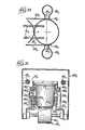
- Machine 30 comprises support framing 32, a strip supply reel 34, a winding mandrel 36, a motor driven winding drum 38, an idler drum 40, and a winding belt 42.
- Winding belt 42 As seen, as the winding belt 42 is driven in the direction shown, its wrapped section 44 drives the spiral tube T around the mandrel 36, and may both uncoil the elongated continuous plastic strip S to continue the formation of the continuous spiral wound tube T, and to drive the tube T downwardly.
- the spiral winding machine 30 may be of a generally conventional type known for use in forming toilet paper rolls, frozen juice cans, and a host of other spirally wound tubular products presently available for domestic and industrial uses.
- the strip S is formed from a web of polystyrene foam or expanded polystyrene material having a thickness of from about .002 inch to about .004 inch, it being desired to use the thinnest possible material for speed of shrinkage and economy.
- substantially thicker materials can be used in the range, for example, of from about .020 inch to about .040 inch.
- Such thicker materials may have a density on the order of 10 to 30 pounds per cubic foot, and while heat-shrinkable expanded polystyrene is a preferred material, other heat-shrinkable expanded thermoplastic materials, sach as polypropylene, polyethylene, and polyvinyl chloride are also appropriate for use in the present invention.
- the strip S may be about one inch wide and may have a substantial degree of orientation and shrinkability in the longitudinal direction of the strip.
- the strip is oriented primarily in the direction of its length and is therefore shrinkable primarily in that direction. It is not necessary that there be shrinkability in the other direction (perpendicular to'the machine direction), but some shrinkability in that direction is permissible.
- the strip S may be printed with textual or decorative material, or both, and in a pattern which will compensate, after shrinking, for the shrinking to provide the desired image and proportioning of text and design, all as is known and understood in the art.
- the strip S may also be joined or laminated with other materials to provide suitable decorative or functional finishes, the only requirement being that such other materials not interfere with the shrinking and sealing of the strip S.
- the longitudinally oriented strip As the longitudinally oriented strip is uncoiled and drawn from supply reel 34, it passes an adhesive applying station 46.
- the adhesive is applied, as by spray heads in a known manner, to the marginal edge of the strip so that when the strip is wound, as by overlapping, with the preceeding turn of the strip on the mandrel, the adhesive will cause the overlapped portions to adhere, thus to form the integrated continuous tube T.
- adhesive may be used to integrate the tube, depending upon the plastic of which strip-S is formeq and its properties, solvents may be used to facilitate bonding. Under properly controlled circumstances, heat softening may also be utilized to bond overlapped portions of the strip, thereby to form a integrated tube T which is shrinkable primarily in the radial direction.
- the overlap is as little as reasonably possible.
- an overlap of as little as 1/16" may be used, although an overlap of about 1/8 inch, 3/16 inch or even slightly more may be used as well.
- belt 42 drives the tube T continuously downwardly.
- the width of the belt 42 is preferably slightly less than the width of the strip S.
- a suitable cutter such as a knife 52 mounted for rotation about shaft 54.
- the cutter is shown as operating externally of the tube T, internal cutters may be used as well. Because tube T is heat-shrinkable primarily in the radial direction, each band B is also heat-shrinkable primarily radially.
- band B may be seated on a transfer applicator 56 which is mounted on a rotatable transfer turret 58. Turret 58 then carries bands B about shaft 59 to the sealing station 60.
- Filled containers 10 having associated affixed closures 12 are continuously supplied to sealing station 60.
- container carriers 62 which are configured suitably for the particular containers, convey and guide suitably filled containers to the supply station. Of course appropriate closures are in place on the containers.
- a transfer applicator carrying a band B moves synchronously to engage a band B with a container 10, for example, by bringing the leading edge of the band B into engagement with the leading edge of the container closure (see FIGURE 3).
- Camming guides 64 then engage a band B in zones adjacent the side edges of the transfer applicator 56, and cam and guide the band B downwardly, both out of engagement with the transfer applicator 56 and to the appropriate, pre-determined elevation relative to the container and closure.
- the band is preferably only slightly larger in diameter than the external diameter of the closure so that it will remain at the selected elevation. If it will not, suitable elevation maintainance guides or stops may be provided in association with the container carriers or otherwise.
- a source of heat such as heat tubes 68, direct heat against the bands B.
- the bands will shrink in the longitudinal direction of the original strip (radially of the formed bands B)
- they quickly shrink about the closure to embrace and grip the closure, thereby also to overlie a peripheral portion of the top of the closure 12 and to grip the portion 16 of the container 12 immediately below the closure, all as illustrated in FIGURE 3.
- the containers 10 are rotated as the heat is applied. That may be facilitated by providing a driven belt 70 which engages the containers and which biases it against a guide bar 72.
- bands B have been illustrated and described as embracing only the peripheral portion of the closure 12, the present invention also contemplates that the entire top surface of the closure may be covered. With such an arrangement, the band will have an axial dimension greater than that illustrated in FIGURE 3, so that upon heating the top edge of the band will shrink together to form a continuum of thermoplastic material. If it is desired to have a completely smooth thermoplastic layer, a heated platen having a flat surface may be applied to the thermoplastic continuum to smooth out any wrinkles therein.
- Carriers 62 are capable of carrying a double row of containers through the sealing station. Tandem forming, winding, transferring and applying mechanisms thus may be used if desired.
- bands B can be formed in diameters as small as 1/2 or 3/4 inch, and as large as six inches or more. For most medical applications (such as for bottles of capsules) they will range from one-half to less than two inches in diameter. For food applications, they may range from about one to two inches, although in some food applications the diameters can run as much as six inches or more.
- the width of a strip S should be such that when it is wound upon the mandrel, the machine direction (the direction in which the strip has been primarily oriented), should be at an angle of no more than about 35° to a plane perpendicular to the axis of the tube T.
- the strip S is wound such that the angle of intersection of the primary direction of orientation of the strip (which is usually parallel to the edge of the strip) with a plane perpendicular to the axis of the tube is no more than about 35 degrees.
- the smaller the diameter of the band to be formed the narrower the strip S which may permissibly be used.
- the greater the diameter of the band to be formed the greater the permissible width of the strip S.
- the strip is provided with some degree of heat-shrinkability in the direction perpendicular to the machine direction, i.e., is partially biaxially oriented, the angle at which the strip S is inclined may be increased somewhat.
- strips S of about one inch should be used to form the tube T.
- strip widths of about one inch to 1-1/2 inches are most desirable, and for band diameters in excess of 1-1/2 inches, strip widths of 2 inches or more will be most desirable.
- this must be balanced with the needed shrink characteristics of the tubular bands severed :rom the continuously formed tube.
- a spiral wound tube T may be flattened and wound into a flattened coil C, with the coil C then being trmsported to the sealing machine with which it is to e used.
- the coil C is then cammed open (see Fig. 4), and may then be fed to a cutter and otherwise follow the same path as the bands formed, transfer t:d and applied in the manner above described.
- a coil of flattened spiral wound ube T is cammed open by a cam means 80, following which it is ready to be presented to a knife 52 to be severed, and thence be transferred and used as described in connection with the embodiment of FIGURES 2 and 3.
- each will produce hundreds of tubular bands, each of which is at least 1/4 inch in length.
- Continuous formation of the spiral wound tube T can produce tens of thousands of bands or more.
- the formation of the spiral wound heat-shrinkable tubes to provide shrinkable bands may be with materials other than the relatively brittle expanded polystyrene material described above.
- heat shrinkable expanded thermoplastic materials can be employed, including polypropylene, polyethylene and polyvinyl chloride which may be formed by conventional forming and orienting procedures into strips which are oriented to be shrunk in the direction of the length of the.strip. Brittle material is preferred for anti-tampering purposes.
- Non-expanded, oriented plastic strips may be used as well in the practice of the present invention, and typical oriented, non-expanded, plastic materials include polyethylene, polypropylene and other known orientable materials.
- the continuously formed spiral tube can provide thousands and tens of thousands of bands continuously and without the individual formation required for such bands in prior art machines.
- the strip S from which the tube is formed may be joined, as one coil comes to an end, with a strip of another coil so that the tube T may be formed for many hours and even days in one continuous length, from which bands are severed.
- the coil may produce tens of thousands of bands (hence seals), again without individual band formation and the expensive forming equipment required in prior art operations.
- While generally cylindrical heat-shrinkable members are suitable for application to many types of containers, their application to some types of containers can be problematical.
- the configuration of some containers is such that heat-shrinking application of cylindrical tamper bands thereto must be very carefully controlled to assure uniform shrinkage of the bands so that they properly embrace the containers.
- tamper band application is preferably performed attendant to high speed packaging of products, it is frequently impractical or impossible to sufficiently control and monitor tamper band application to assure the desired interaction of the bands with their associated containers.
- Another problem encountered with heat-shrink fitment of tamper bands or like members to containers relates to the manner in which they are heat-shrunk. After the members have been positioned in association with the containers, the members are shrunk by the application of heat, which is typically accomplished by passing the containers through a heat tunnel or like heat source so that the heat-shrinkable members are substantially entirely heated and shrunk into conformance with the containers.
- a method and apparatus are disclosed for preforming heat-shrinkable members, and subsequently applying the members to associated containers such that the members are conformed to the configuration of the containers.
- the method of the present invention contemplates that a preferably generally cylindrical heat-shrinkable member is first partially heat-shrunk to form a preformed member which may at least partially conform to the configuration of the container to which the member is subsequently applied. The preformed member is then applied to the container and further conformed thereto. While this final application can be achieved by passage of the container through a heat tunnel or the like, the present invention contemplates that only a portion of the preformed member is locally heated, thus minimizing heating of the associated container and its contents.
- the present invention is particularly suited for applying heat-shrinkable, tamper-indicating members to associated containers, it.will be recognized that the invention is readily adaptable for other applications wherein it is desirable to initially partially form a heat-shrinkable member, and thereafter complete formation of the member while it is positioned in association with a container or the like to which it is being applied.
- this technique heretofore unachievable control of the shrinking process is obtained, since the heat-shrinkable members can be partially pre-shrunk to a pre-selected form apart from their final application to containers.
- the heat-shrinkable members to be preformed and applied to containers are in a generally cylindrical form, with the members predominantly shrinkable in a radial direction.
- the heat-shrinkable member is first preformed to a configuration which may at least partially conform to the configuration of the container to which the member is to be applied. Preforming in this manner is accomplished by providing a preforming mandrel.
- the heat-shrinkable member is positioned in association with the preforming mandrel, and the member is then heated. This causes the member to shrink and conform to the configuration of the preforming mandrel, thus forming a preformed member of the pre-selected configuration.
- preforming is effected apart from application of the heat-shrinkable member to ⁇ -4 container, the preforming can desirably be carefully controlled. Further control of the performing method is provided by releasably retaining an annular edge portion of the heat-shrinkable member as it is heated for conformance to the performing mandrel. Releasable retention in this manner acts to assure the uniformity of the resultant preformed member.
- the preformed member After the preformed member has been moved from association with the preforming mandrel, the preformed member is positioned in association with the container to which it is being applied. Notably, the preformed member can then be applied to the associated container by locally heating only a portion of the preformed member.
- the localized heating of the preformed member is preferably performed so as to minimize any heating of the associated container and its contents.
- final application can also be effected by heating of the entire preformed member, such as by a passage through at heat tunnel.
- engagement means can be provided for moving a portion of the preformed member into conformance with the container, such as the locally heated portion of the member.
- the engagement means are provided by an engagement roller which is adapted to engage a portion of the preformed member by rotation of the container and the preformed member with respect to the engagement roller.
- FIGURE 5 illustrates a generally cylindrical, heat-shrinkable member H B to be preformed and subsequently applied to an associated container.
- member HB is illustrated as spirally wound, formed in accordance the teachings of copending U.S. patent application 451,401, filed December 20, 1982.
- the member H B is preferably formed from a heat-shrinkable thermoplastic material, such as expanded polystyrene, polypropylene, polyethylene, or polyvinyl chloride.
- the member HE is generally cylindrical as illustrated, it is preferably, configured so as to be predominantly heat-shrinkable in a radial direction relative to its axis.
- the heat-shrinkable member H B is adapted to be applied to container 10 B , illustrated in FIGURE 9.
- Container 10 B is intended to be illustrative of a typical container construction, since it will be appreciated that the present invention can be readily practiced for applying heat-shrinkable members to containers of almost an endless variety of configurations.
- the container 10 B includes a lid portion 12 B , and a bottom portion 14 B which is generally downwardly inwardly tapering.
- the present invention contemplates the preforming and subsequent application of heat-shrinkable member H . to container 10 B so that attempted opening or opening of the container by removal of its lid portion 12 B requires permanent visible deformation of the heat-shrinkable member for tamper-indicating.
- the invention can also be employed for application of other than tamper-indicating members, such as protective sleeves that are sometimes fitted to containers.
- the present invention can be employed for forming and applying a combination protective sleeve/tamper band, which may also provide a label for the associated container.
- a protective sleeve or the like on a container desirably acts to rigidity the container itself, thus permitting the container to be made from relatively lighter gauge material for desired economy in fabrication of the container.
- application of heat-shrinkable members to provide labels for containers desirably permits the use of a single type or color of container for diffeent varieties of a product, with appropriately different heat-shrinkable labels applied to the like containers to identify the different varieties of the product.
- FIGURE 6 illustrates a heat-shrinkable preformed member P B formed from the member H of FIGURE 5 in accordance with the present invention.
- preformed member P B has a configuration which is at least partially conforming to the configuration of container 10 B to which it will be applied.
- the formation of preformed member P B from member H B is effected by use of a preforming mandrel 20 B , illustrated in FIGURE 7.
- Preforming mandrel 20 B is partially configured like the container 10 B , more specifically, the mandrel 20 B has a generally inwardly tapering configuration like the inwardly tapering configuration of the bottom portion 14B of container 10 B .
- the preforming mandrel will be at least partially generally configured like the container to which the preformed member P B is to be applied, but the configuration of the preforming mandrel is selected to form member P B to the desired configuration which facilitates subsequent application of member P B to a container, and thus the mandrel 20 B is not necessarily configured like the container.
- FIGURE 8 diagrammatically illustrates the formation of preformed member P B from heat-shrinkable member H B by the use of preforming mandrel 20 B and a retaining member 21 B .
- the heat-shrinkable member H B is positioned in association with preforming mandrel 20 B such that the member H B extends generally about the preforming mandrel.
- retaining member 21 B and preforming mandrel 20 B are relatively moved so that a preferably continuous retaining lip portion 23 B of the retaining member is positioned in association with the annular edge portion of the member H B generally adjacent and inwardly of the annular edge portion.
- retaining member 21 B acts to releasably retain the edge portion of member H B during heating of the member H B to facilitate formation of preformed member P B .
- a progressive shrinking action is provided. Since the lower portion of the member H B is in relatively closer association with preforming mandrel 20 B when heat-shrinking is initiated, that portion requires a somewhat greater heat input to shrink into the desired conformance with mandrel 20 B . In contrast, the free upper portion of member HB' which is spaced further from mandrel 20 B , would begin to shrink relatively quickly if not releasably retained, and thus fold over or otherwise shrink in an unintended manner.
- the retaining member 21 B releasably retains the upper edge portion of member H B during heat-shrinking, thus allowing sufficient time for the remainder of the member H B to move toward conformance with mandrel 20 B . Subsequently, the upper edge portion of member H B slips off of lip portion 23 B of retaining member 21 B to complete formation of preformed member P B of the desired uniformity.
- the entire member H B is subjected to heat causing it to shrink inwardly and conform to preforming mandrel 20 B so that preformed member P B is formed.
- the preforming mandrel 20 B is preferably configured to accommodate the passage of air from between the preforming mandrel and the heat-shrinkable member H B as the member H B shrinks onto the preforming mandrel.
- preforming mandrel 20 B defines a plurality of vent passages 22 B to prevent build-up of air between the preforming mandrel 20 B and the heat-shrinkable member H B which could otherwise form air bubbles or like irregularities in the resultant preformed member P B .
- Suction means applied through vent holes defined by preforming mandrel 20 B can also be employed to prevent undesired irregularities.
- the heat for shrinking heat-shrinkable member H B to form preformed member P B is provided from a suitable heat source designated 24 B .
- This heat source may comprise a heat tunnel or oven within which the preforming mandrel 20 B and the heat-shrinkable member H B are positioned, or may comprise a heat source which acts directly against only a portion of heat-shrinkable member H B , with rotation of preforming mandrel 20 B and retaining member 21 B together with heat-shrinkable member H B assuring the complete heating of member H B so that preformed member P B is formed.
- the preformed member is preferably formed to be slightly larger than the container. This can be achieved by sizing preforming mandrel 20 B to be slightly larger than the portion of the container to which the member P B is to be applied, or by controlling the preforming heat-shrinking of member H B so that it does not conform too tightly to the preforming mandrel.
- FIGURES 9-14 diagrammatically illustrate application of preformed member P B to container 10 B so that the preformed member is further conformed to the configuration of container 10 8 .
- the member P B is conformed to the container such that opening of the container by removal of its lid portion 12 B results in permanent, visual deformation of the preformed member P B .
- FIGURES 9 and 10 illustrate movement of container 10 B and preformed member P B into association with each other and into association with the portion of the apparatus of the present invention for applying the preformed member P B to the container 10B.
- the apparatus can include a supporting member 30 B adapted to receive the preformed member P B and the container 10 B , as illustrated in FIGURE 10.
- Supporting member 30 B may comprise one of a plurality of such supporting members provided on a rotary, turret-type packaging machine adapted for sequential, high speed application of preformed members such as P B to respective associated containers such as 10 B .
- the member P B conforms to the portion of the container which generally provided the profile of preforming mandrel 20 B .
- the apparatus may include an ejector member 32 B which is vertically movable with respect to supporting member 30 B to facilitate ejection of container 10 B and its heat-shrinkable member P B after application of member P B is complete.
- the present apparatus may include a rotating drive member 34 B which is positioned atop lid 12 B of container 10 B by relatively vertically moving the member 34 B and the container 10 B .
- the preformed member P B is now ready to be further heated so that it further shrinks and conforms to container 10 B , specifically so that the preformed member P B overlies a portion of the lid portion 12 B of the container.
- Localized heat source 36 B is provided for this purpose.
- Heat source 36 B may comprise a nozzle or the like for directing a heated air stream against a portion L B of preformed member P B which is to be locally heated.
- the heat source 36 B is preferably configured to minimize the impingement of heat energy on other than locally heated portion L B .
- the locally heated portion of the preformed member P B in the illustrated embodiment comprises the portion.of the member P B opposite from its inwardly-most tapered portion.
- the configuration of supporting member 30 B which receives substantially the entire container 10 B
- the configuration of rotating drive member 34 B which substantially covers the entire lid portion 12 B of the container, further act to minimize the heating of container 10 B by localized heat source 36 B .
- the container 10 B and preformed member P B are preferably rotated with respect to heat source 36 B , as illustrated in FIGURE 12. Rotation in this manner can be effected by rotation of rotary drive member 34 B and/or by rotation of supporting member 30 B . As the container and the preformed member P B are rotated, all of the locally heated portion L B of member P B is heated so that it shrinks and thereafter conforms to configuration of container 10 B , specifically by moving into overlying relation with the cover 12 B of container 10 B .
- means are preferably provided for moving the locally heated portion L B of preformed member P B into association with container 10 B .
- Such moving of locally heated portion L B with engagement roller 38 B can be performed in conjunction with the local heating of portion L B with localized heat source 36 B , or may be performed just after the localized heating of portion L B while portion L B is still sufficiently pliable.
- FIGURE 14 illustrates the completed application of preformed member P B to container 10 B after the locally heated portion L B of preformed member P B has been moved to its final position in association with the container.
- the container 10 B can then be ejected from supporting member 30 B such as by relative vertical movement of the supporting member 30 B with respect to ejector member 32 8 .
- the container 10 B can then be moved from the apparatus for subsequent packaging, storage, and shipment.
- This aspect of the present invention relates to a method and apparatus for cutting individual tube segments in a highly efficient matter, preferably in conjunction with formation of a spirally wound tube of material. While past arrangements for cutting tubular material have typically operated to cut the material from its outer surface, the present invention uniquely functions to internally cut the tube of material into segments.
- the present method and apparatus permit highly efficient formation of tubular segments from a tube of material by internally cutting the tube of material, preferably in conjunction with formation of the tube of material by spirally winding a generally continuous strip or the material.
- the apparatus disclosed is desirably relatively compact, and is particularly adapted to be integrated with an apparatus for forming a spirally wound tube of material, thus facilitating cutting of the tube into segments of any desired length as the tube is formed.
- the invention facilitates very high speed formation of individual tube segments, thus promoting their economical manufacture.
- the resultant bands can be very inexpensively manufactured, yet are highly effective for visually indicating opening of associated containers to which the bands are affixed.
- the apparatus of the present invention includes a frame which supports a generally cylindrical forming mandrel upon which the tube of material to be cut is carried, with the tube being adapted to be relatively advanced along the mandrel toward a free end thereof.
- the mandrel provides the structure upon which the tube of material may be continuously spirally wound, with formation of the tube in this manner acting to advance the tube along the mandrel of the apparatus in the desired fashion.
- the apparatus of the present invention further includes a rotary cutter assembly rotatably mounted in the forming mandrel for rotation about an axis coinciding with the centerline or longitudinal axis of the mandrel.
- a cutter drive arrangement is provided for continuously rotating the cutter assembly within the mandrel, with the cutter assembly including one or more cutting blades which are adapted to reciprocably move outwardly and inwardly of the mandrel at the free end thereof.
- the one or more cutting blades act to intermittently internally cut and sever the tube of material when the blades are moved outwardly of the mandrel, and thus form tubular segments from the continuous tube of material.
- An important feature of the present invention is its adaptability for very high speed formation of tubular segments.
- the apparatus of the present invention is uniquely configured to operate such that the cutting blades of the cutter assembly move axially of the forming mandrel in the direction of advancement of the tube of material on the mandrel during cutting of the tube.
- each cut formed in the tube of material is circular and extends in a plane which is substantially perpendicular to the axis of the tube of material.
- the result is formation of tube segments which are substantially cylindrical.
- the present invention is used for formation of heat-shrinkable tube segments, their substantially cylindrical configuration facilitates subsequent heat-shrink fitment to associated containers.
- the cutter assembly of the present apparatus includes a cutter arbor which extends concentrically within the forming mandrel, and a blade actuating rod which extends concentrically within the cutter arbor.
- the cutter drive of the apparatus is adapted to rotatably drive the cutter arbor and the blade actuating rod together within the forming mandrel of the apparatus. While the blade actuating rod and cutter arbor are adapted to be rotatably driven together, the arbor and actuating rod are adapted for relative axial movement with respect to each other, as well as with respect to the forming mandrel.
- the one or more cutting blades of the apparatus are operatively connected with the blade actuating rod of the cutter assembly so that reciprocable, relative axial movement between the cutter arbor and the actuating rod acts to reciprocably move the cutting portion(s) of the one or more cutting blades inwardly and outwardly of the forming mandrel at its free end.
- This relative axial movement is effected by means of a cam mechanism which operates to axially move the cutter arbor and blade actuating rod with respect to each other, as well as with respect to the forming mandrel.
- An arrangement of flanged couplings and cam links operatively interconnects a timing cam arrangement with the blade actuating rod and the cutter arbor to permit their axial movement as they rotate within the forming mandrel.
- the cam mechanism operates to first relatively axially move the cutter arbor and blade actuating rod to move the one or more cutting blades of the cutter assembly outwardly of the forming mandrel.
- the cam mechanism further operates to axially move the actuating rod and cutter arbor together within the forming mandrel in the direction of tube advancement so that the cutting blades of the apparatus move in the direction of tube advancement during internal cutting of the tube.
- FIGURE 15 therein is illustrated a tube cutting apparatus 10 C embodying the principles of the present invention. While the apparatus 10 c is illustrated in a general vertical orientation, it will be recognized that the apparatus can be readily otherwise positioned for operation. Accordingly, terms such as upper and lower used in this disclosure will be understood as referring to the apparatus in its illustrated orientation, and will be further understood as not suggesting that the present apparatus cannot be oriented other than generally vertically.
- Apparatus 10 C includes a frame 12 C from which depends a mandrel assembly, generally designated 14C.
- the mandrel assembly includes an upper mandrel portion 16 G affixed to frame 12 C , and a lower, cylindrical forming mandrel 18 C which depends from the upper portion 16 C .
- the forming mandrel 18 C is adapted to carry a tube of material to be cut into tubular segments.
- the forming mandrel 18 C is preferably sized for the desired diameter of the tubular segments to be formed.
- the tube of material to be cut is formed on forming mandrel 18 C by spiral winding.
- FIGURE 15 diagramatically illustrates a strip of material M C being wound on forming mandrel 18 c to form tube T C .
- a driven winding belt (not shown) is preferably provided for spirally winding the tube T C from the strip of material M C .
- the formed tube of material rotates about the forming mandrel 18 cl with the tube of material being relatively advanced toward the free end of the forming mandrel 18 C , as indicated by arrow A C .
- the forming mandrel 18 C is preferably threadably or otherwise releasably connected with the upper mandrel portion 16 C , thus facilitating replacement of the forming mandrel 18 C with differently sized mandrels for forming tube T C of the desired diameter.
- a rotary cutter assembly 20 C is provided within the mandrel assembly 14 C .
- the cutter assembly 20 c is preferably arranged concentrically within the mandrel assembly 14 C , and is rotatably supported therein by upper and lower bearings 22 C and 24 C .
- the cutter assembly 20 C is adapted to rotate about an axis coinciding with the centerline of mandrel assembly 14 C , with the cutter assembly preferably configured for relatively high speed rotation, such as on the order of 1000-2000 revolutions per minute.
- the cutter assembly includes a generally cylindrical cutter drive member 26 c having one end which extends above frame 12 c with a cutter drive pulley 28 C affixed thereto.
- a cutter drive motor 30 C is mounted on frame 12 C , with a motor drive pulley 32 C affixed to the motor shaft acting through a cutter drive belt 34 C to rotate cutter assembly 20 C within mandrel assembly 14 C .
- the rotary cutter assembly 20 C further includes an elongated, generally cylindrical cutter arbor 36 C which extends within cutter drive member 26 C , and extends within mandrel assembly 14 C from the free end of forming mandrel 18 C to above frame 12 c of the apparatus.
- the cutter arbor 36 C is adapted for rotation together with cutter drive member 26 C , and is further adapted for axial movement with respect to the drive member 26 C as they rotate together.
- a first flanged cam coupling 38 C is keyed to cutter arbor 36 c above cutter drive pulley 28 C .
- a drive pin 40 C extends from drive member 26 C and drive pulley 28 C partially into a pin drive opening 41 c defined by first flanged coupling 38 C .
- the cutter arbor 36 C which is illustrated in FIGURE 15 in its upwardly-most position with respect to mandrel assembly 14 C , is adapted to move axially downwardly of drive member 26 C and mandrel assembly 14 C .
- Bushings 42 c and 44 C disposed between drive member 26 C and cutter arbor 36 C facilitate relative axial movement between the drive member and cutter arbor as they rotate together.
- the rotary cutter assembly 20 C further includes an elongated blade actuating rod 46 C which is disposed within cutter arbor 36 C and extends substantially the length thereof.
- the blade actuating rod 46 C is also adapted for rotation with cutter arbor 36 C and drive member 26 C , and to this end, a rod drive coupling 48 C is affixed to actuating rod 46 C near the upper end thereof with a pin 50 C or like fastening means.
- the rod drive coupling 48 C includes a key portion 52 c which is received within a key slot portion 54 C of cutter arbor 36 C .
- a second flanged cam coupling 56 C is connected to blade actuating rod 46 C .
- a bushing 58 C is interposed generally between the upper end of cutter arbor 36 C and the second flanged coupling 56 C to accommodate axial movement of the coupling 56 C with respect to the cutter arbor.
- An end nut 60 C threadingly engages the second flanged coupling 56 C , and affixes the coupling 56 c to the rod drive coupling 48 C for rotation of the flanged 56 c coupling together with blade actuating rod 46 C .
- cutter drive member 26 C rotatably drives cutter arbor 36 C , which in turn rotatably drives blade actuating rod 40 C .
- the cutter arbor 36 C is relatively axially movable within cutter drive member 26 C , with blade actuating rod 46 c being likewise relatively axially movable within the cutter arbor 36 C .
- the present invention contemplates that attendant to reciprocable relative axial movement of cutter arbor 36 C and blade actuating rod 46 C , one or more cutting blades of the rotary cutter assembly 20 C are moved inwardly and outwardly of forming mandrel 18 C at its free end.
- this cutting action is provided by one or more flexible cutting blades 66 c (two being illustrated).
- Each blade 66 C has one end operatively connected with the blade actuating rod 46 C , such as by disposition of the ends of blades 66 c in a split portion of the rod 46 C , with the blades secured such as by pin 68 C .
- the blades 66 c extend generally outwardly in opposite directions from the blade actuating rod 46 C , with the inward and outward movement of the blades 66 c with respect to forming mandrel 18 C preferably guided by a pair of the guide rollers 70 c mounted on cutter arbor 36 C in respective operative engagment with blades 66 C .
- the movement of blades 66 C is further preferably guided by a guide disc 72 C carried by cutter arbor 36 C having suitably shaped arcuate guiding surfaces so that the cutting end portions of blades 66 c move inwardly and outwardly of forming mandrel 18 C attendant to relative axial movement of cutter arbor 36 C and blade actuating rod 46 C .
- a further pair of guide rollers can be provided on the guide disc 72 c for respectively guidingly engaging the blades 66 C generally along the downwardly facing surfaces of the cutting portions of the blades.
- the present apparatus includes a cam mechanism which operates to not only relatively axially move actuating rod 46 C and cutter arbor 36 c for reciprocably moving blades 66 C inwardly and outwardly of forming arbor 18 C , but which also operates to move the blades 66 C in the direction A of tube advancement during cutting.
- the cam mechanism of the present apparatus includes a cam support 78 C mounted on frame 12 C , and which rotatably supports a cam shaft 80 C by means of bearings 82 C (FIGURE 17).
- the cam shaft 80 C is driven via a drive coupling 84 C , with power to the coupling 84 C provided by a cam drive motor 86 C operating via a cam drive gearbox 88 C , both of which are mounted on frame 12 C .
- Axial movement of cutter arbor 36 c and blade actuating rod 46 C is adapted to be effected via first and second flanged cam couplings 38 c and 56 C , and to this end the cam mechanism includes a pair of cams 90 C each having the same cam profile, both of the cams 90 C being mounted on cam shaft 80 C on respective opposite sides of cam support 78 C .
- the cams 90 c effect axial movement of cutter arbor 36 C via a pair of first cam follower links or rockers 92 C affixed to respective opposite ends of a link rocker shaft 94 c rotatably supported on cam support 78 C so that links 92 c are pivotally movable together.
- Each of follower links 92 C has mounted thereon at one end a cam roller follower 96 C for operative engagement with a respective one of cams 90 C , with each link 92 C acting through first flanged cam coupling 38 c (affixed to cutter arbor 36 C ) by a respective coupling roller 98 c disposed between the flanges of coupling 38 C . While it will be recognized that the desired axial movement of cutter arbor 36 C could be likewise effected through a single cam follower link 92 C , the provision of a pair of links 92 C operating on opposite sides of flanged coupling 38 c obviates problems of cocking or the like of the coupling 38 c which could otherwise interfere with the desired high speed operation of the present apparatus.
- the cam mechanism of the apparatus further includes a pair of second cam follower links or rockers 100 C which are also fixed to respective opposite ends of a rocker shaft 102 C rotatably supported in cam support 78 C for pivotal movement of the follower links 100 C together.
- Each follower link 100 C has mounted thereon at one end a cam roller follower 104 c for operative engagement with a respective one of cams 90 C , with the other end of each follower link 100 c having a coupling roller 106 C operatively disposed between the flanges of second flange cam coupling 56 C connected with blade actuating rod 46 C .
- a pair of cam springs 108 C held in captive relation between each respective pair of links 100 C and 92 C assures positive operative engagement of the follower links with the cams 90 C .
- the desired mode of cutting operation by axial movement of blade actuating rod 46 C and cutter arbor 36 C can be commonly effected by cams 90 C operating through both first and second cam follower links 92 C and 100 C .
- this permits the present apparatus to be quite compact and readily fabricated at minimum expense.
- other cam arrangements can be readily employed for effecting the desired axial movement of cam actuating rod 46 C and cutter arbor 36 C .
- the arrangement can be fabricated other than as illustrated depending upon the exact cutting action desired.
- the cam profiles, the relative positions of first and second follower links 92 C and 100 C , the length and fulcrum points of the follower links, and other design parameters can be very widely varied to effect operation as follows.
- blade actuating rod 46 C and cutter arbor 36 C are positioned in their upwardly-most dispositions. Spiral winding of tube of material T C on forming mandrel 18 C is initiated such that the formed tube of material advances in direction A along forming mandrel 18 c toward its free end.
- flexible cutting blades 66 C are in their retracted position with respect to forming mandrel 18 c so that the formed tube of material T C can pass by the blades and off of the free end of mandrel 18 C .
- Cutter drive motor 30 C is then started so as to rotate cutter assembly 20 C within mandrel assembly 14C.
- Cam drive motor 86 C is next started to initiate cutting, with selected variation in the speed of cam drive motor 86 C and the speed of formation of tube T C by spiral winding permitting tubular segments S c of various selected dimensions to be formed.
- cams 90 C operate through the cam follower links 100 C to first relatively axially move blade actuating rod 46 C with respect to cutter arbor 36 c so that the cutting portions of flexible blades 66 c are moved outwardly of and extend beyond the outer surface of forming mandrel 18 C , as illustrated in FIGURE 16.
- the cams 90 C thereafter act through the cam follower links 92 c and 100 C to axially move blade actuating rod 46 C and cutter arbor 36 C together with respect to mandrel assembly 14 C .
- the cutting portions of flexible blades 66 C are moved in the direction A C of advancement of tube of material T C as the blades internally cut the tube to form tubular segment S C .
- the speed with which tube of material T C is being advanced toward the free end of forming mandrel 18 C is constant, it will be recognized that the speed of axial movement of blades 66 c in the direction of tube advancement must be the same as the speed of tube advancement to form tubular segments which are actually truly cylindrical. In practice, however, the speed of axial blade movement can be somewhat greater or somewhat less than the speed of tube advancement while still permitting formation of tubular segments S c which are sufficiently cylindrical in configuration to be acceptable. An excessive difference between the speed of tube advancement and the speed of axial blade movement results in the formation of spiral rather than circular cuts in the tube T C .
- the axial movement of blade actuating rod 46 C and cutter arbor 36 c is reversed to complete the cutting cycle.
- the actuating rod 46 C is first axially moved relative to the cutter arbor so that the cutting portions of blades 66 C are retracted inwardly of the outer surface of forming mandrel 18 C , and the actuating rod 46 C and the cutter arbor 36 C are thereafter axially moved together upwardly within mandrel assembly 14 C in the direction opposite of the direction of tube advancement. Retraction of the cutting portions of blades 66 C before upward movement of the blades prevents interference with the tube of material T C as it is advanced along and past the free end of forming mandrel 18 C .
- cutter assembly 20 C is preferably rotated in the direction of spiral winding of tube T C .
- tube T C is being fomed by attendant to rotation about forming mandrel 18 C in a counter-clockwise direction (when viewed from the free end of the mandrel)
- spiral winding of the tube is effected clockwise, and thus cutting of the tube is preferably likewise effected in a clockwise direction, although the cutting of the tube can be effected in a direction opposite to the direction of spiral tube formation.
- FIGURE 19 illustrates a modified cutter assembly for the present apparatus.
- a modified cutter arbor 136 C rotates within forming mandrel 18 C and is adapted for relative axial movement therein in the manner described above.
- This embodiment further includes a modified blade actuating rod 146c which extends within cutter arbor 136 C for rotation therewith, and which is adapted for relative axial movement with respect thereto.
- the blade actuating rod 146 C includes a blade cam portion 147c at its free end, with relative axial movement of the actuating rod 146 c with respect to the cutter arbor 136 C being adapted to provide inward and outward movement of a blade block 149 C with respect to forming mandrel 18 C .
- Blade block 149 C is carried by cutter arbor 136 C such as by suitable slots or the like, with the blade block 149 C carrying a cutting blade 151 C adapted to move inwardly and outwardly of the outer surface of forming mandrel 18 C .
- a pair of blade cam rollers 153 C are mounted on blade block 149 C , thus operatively connecting the blade block and the blade 151 C with the blade actuating rod 146 C .
- this modified embodiment of the rotary cutter operates somewhat differently than the previously described cutter arrangement in that upward axial movement of actuating rod 146 C with respect to cutter arbor 136 C causes the cutting portion of blade 151 C to move outwardly, and vice versa.
- the cam mechanism of the apparatus for axially moving the cutter arbor 136 C and the blade actuating rod 146 C can be suitably modified for effecting the axial movement of the actuating rod and the cutter arbor in the desired timed manner.
- This aspect of the present invention contemplates a method and apparatus for continuously and automatically applying annular-shaped, heat-shrinkable members to containers.
- the arrangement includes a very efficient vacuum-operated transfer mechanism for continuously positioning the heat-shrinkable members in respective association with a continuous supply of containers.
- the apparatus can include a unique arrangement for supporting and positioning each heat-shrinkable member in a predetermined position with respect to its associated container prior to heating of the member for heat-shrink fitment to the container.
- This feature of the present invention facilitates application of an appropriately sized heat-shrinkable member to a container which is not suitably configured to support the heat-shrinkable member in the desired relative position prior to and during heat-shrinking of the member into conformance with the container.
- the apparatus of the present invention includes a container conveyor for carrying and moving the containers to which the annular-shaped, heat-shrinkable members are to be respectively applied.
- the apparatus further includes a feed magazine positioned in association with the container conveyor for holding a quantity of the heat-shrinkable members.
- the feed magazine is preferably inclined so that the feed of the heat-shrinkable members is by gravity.
- the apparatus further includes a transfer mechanism for transferring the heat-shrinkable members from the feed magazine into respective association with the containers on the conveyor.
- the transfer mechanism is positioned above the container conveyor, and functions such that the heat-shrinkable members are sequentially releasably retained at an acute angle with respect to the direction of movement of the container conveyor.
- each container acts against its respective member by engagement with its inside surface to move the member from the transfer. mechanism into association with the container for subsequent heat-shrinking.
- the transfer mechanism includes means for applying suction to the transversely opposite outer sides of each heat-shrinkable member for releasably retaining each member.
- the transfer mechanism further preferably includes a pair of stops positioned adjacent the suction-applying means.
- the stops are spaced apart a distance less than the transverse dimension of each heat-shrinkable member, and thus coact with the suction-applying means to releasably retain each member for transfer to its respective container.
- the present apparatus further includes a heat tunnel or the like for heating each heat-shrinkable member so that it shrinks into conformance with its respective container.
- a heat tunnel or the like for heating each heat-shrinkable member so that it shrinks into conformance with its respective container.
- some containers are configured such that each container supports its respective heat-shrinkable member in the desired relative position, so that subsequent heating of the member shrinks it into the desired conformance with the container, such as for formation of a tamper band.
- the present apparatus includes means for supporting each heat-shrinkable member is a predetermined position relative to its respective container prior to the member being heat-shrunk into conformance with the container.
- the positioning means comprises a pair of support rails which extend generally from the transfer mechanism of the apparatus into its heat tunnel. To avoid excessive heating of the rails so that the heat-shrinkable members do not begin to soften and stick-to the rails, or shrink in an undesired manner as soon as they contact the support rails, means are provided for cooling the support rails.
- the present apparatus preferably includes means for rotating the containers with respect to the container conveyor as the heat-shrinkable members are heated.
- FIGURES 20 and 21 diagrammatically illustrate an apparatus 10 D embodying the principles of the present invention for applying heat-shrinkable members to containers.
- the present apparatus is adapted to automatically and continuously function to sequentially or serially apply the heat-shrinkable members, designated M D , in respective association with the containers, each designated C D , and each including a lid portion L D .
- Each heat-shrinkable member M D is annular-shaped and generally cylindrical in configuration, with each being appropriately sized relative to the dimensions of each container C D for the intended purpose of the heat-shrinkable members.
- heat-shrinkable members M D are illustrated of a size which is appropriate for formation of tamper-evident seals (i.e., tamper bands) on containers C D .
- Each member M D is preferably predominantly heat-shrinkable in a radial direction with respect to the axis of each member.
- Members M D having this characteristic can be very efficiently formed by spiral winding in accordance with the teachings of copending U.S. patent application Serial No. 451,401, filed December 20, 1982.
- each member M D comprises suitably thin, heat-shrinkable material, preferably expanded polystyrene.
- Other heat-shrinkable expanded thermoplastic materials such as polypropylene, polyethylene, and polyvinyl chloride, can also be used.
- formation of members M D from such material results in some resilient flexibility for each of the members M D .
- the apparatus 10 D of the present invention includes a container conveyor, designated 12 D , including an upper run 14 D for carrying and moving containers C D in the direction of the arrows shown in FIGURE 20.
- the conveyor 12 D can include suitable conveyor rollers 16 D for support thereof. Because containers C D are preferably carried on conveyor 12 D so that the portions of the containers that receive members M D are spaced apart, the containers C D may be supplied to conveyor 12 D from a feed conveyor 18 D which moves at a speed less than that of conveyor 12 D for spacing the containers on conveyor 12D.
- the present method contemplates that the heat-shrinkable members M D are positioned in respective association with the containers C D for subsequent heating of the members M D so that they shrink into conformance and embrace each container C D .
- the apparatus 10 D includes an inclined gravity feed magazine 20 D positioned in association with conveyor 12 D .
- the feed magazine 20 D is adapted to hold a quantity of the members M D for sliding movement by gravity.
- the members M D intermittently move within the feed magazine 20 D as the members M D are received one-at-a-time by a transfer mechanism, designated 24 D , positioned at the end of the feed magazine above container conveyor 12 D .
- The-transfer mechanism 24 D functions to releasably retain each member M D so that each member extends into the path of the moving containers.
- Each member M D is releasably held relative to the moving containers C D at an acute angle with respect to the direction of movement of containers C D on conveyor 12 D .
- the forwardly disposed inside surface each member M D is engaged by a forwardly disposed portion of its respective one of the containers C D and withdrawn from the transfer mechanism.
- Each member M is preferably held at an acute angle by the transfer mechanism 24 D in the sense that the plane extending through each member perpendicularly to its axis is disposed at an acute angle to the direction of movement of containers C D . This transfer action is best illustrated in FIGURES 22, 23, and 24.
- the transfer mechanism 24 D includes an arrangement for applying suction to each member M for releasably retaining each member in position for transfer to its respective container.
- the transfer mechanism includes a bifurcated vacuum plenum 26 D connected to a pair of side plates 28 D which extend from feed magazine 20 D .
- Each side plate 28 D defines a preferably slot-like suction port 30 D in communcation with vacuum plenum 26 D such that a suction is created at each suction port 30 D .
- the suction ports 30 D apply suction to transversely opposite outer sides of each heat-shrinkable member M D so that each member M D is releasably retained in position for transfer to its respective container C D .
- the suction ports 30 D are preferably spaced apart a distance which corresponds to the maximum transverse dimension or outer diameter of each heat-shrinkable member M D .
- each suction port 30 D desirably permits suction to be applied to each member M D generally along the vertical extent of each member M D , with suction preferably applied at or just forwardly of the transverse center line of each member M D (see FIGURE 24).
- suction preferably applied at or just forwardly of the transverse center line of each member M D (see FIGURE 24).
- each member M is moved from the transfer mechanism 24 D by engagement by its respective container C D , the following one of the members M D moves downwardly by gravity within feed magazine 20 D and is received within the transfer mechanism.
- An upper plate 29 D and lower guides 31 D of the feed magazine 20 D act to guide each member M D into the transfer mechanism 24 D until the suction applied via suction ports 30 D acts to grip each member and retain it an an acute angle with respect to the container conveyor 12 D .
- a pair of spaced apart, inturned stops 32 D are preferably provided respectively positioned adjacent the suction ports 30 D , with the stops 32 D being formed from portions of side plates 28 D .
- the stops 32 D provide an indexing action by engaging each member M D as it is held by suction ports 30 D to further releasably retain each member M D in position for transfer to its respective container C D . Accordingly, the stops are spaced apart a distance less than the transverse dimension (i.e., diameter) of each member M D .
- feed magazine 20 D and the transfer mechanism 24 D desirably are of straightforward construction for ease of fabrication and maintenance, and provide for highly efficient transfer of members M D into respective association with containers C D .
- the transfer mechanism may include an upper arcuate guide 34 D (shown as a portion of upper plate 29 D ) which is adapted to engage the heat-shrinkable members M D as they are "picked up" by their respective containers C D to assure that the members M D move downwardly into proper position with respect to the containers.
- this transfer step can be effected so as to position each member M D in the desired position relative to its container C D so that subsequent heating of the member M D causes it to shrink and embrace the container C D in the intended manner, such as for tamper-indication.
- the members M D can be transferred to such containers so that each member M D rests upon the shoulder of its respective container. Subsequent heating of the members M D then results in their heat-shrinking into conformance with the containers, such as to embrace the closure of each container for tamper-indication.
- the containers C D in the illustrated embodiment do not include a shoulder portion or the like upon which the members M D can be positioned so that the members are held in the desired relative position with respect to the containers C D .
- the illustrated embodiment of the present apparatus includes an arrangement for positioning each member M D in a predetermined position relative to its respective container C D so that subsequent heating of the member results in its conformance with the intended portion of container C D (i.e., such that the member M D embraces the upper portion of the container C D and its lid portion L D for tamper-indication).
- the positioning arrangement of the present apparatus includes a pair of positioning support rails 36 D which extend on respective opposite sides of container conveyor 12 D .
- Each support rail 36 D is suitably mounted on a rail mount 38 D , with each support rail 36 D defining an internal coolant passage 40 D through which coolant flows for cooling of the support rails.
- the members M D are heated for shrinking by a heat-tunnel 44 D of the apparatus 10 D .
- support rails 36 D extend generally from the point of transfer of members M D to containers C D at transfer mechanism 24 D , in the direction of conveyor movement into heat tunnel 44 D .
- the members M D are slidably supported upon the support rails 36 D prior to and during initial heating of the members M D within heat tunnel 44 D .
- the support rails maintain the members M in a predetermined relative position with respect to the containers C D until the members M D have been sufficiently heated to partially shrink them into conformance with the containers C D sufficiently to hold the members M D in correct position on containers C D for completion of heat-shrink fitment.
- the support rails 36 D extend within heat tunnel 44 D a sufficient distance to support the members M D until the members M D support themselves on the respective containers CD, the support rails absorb a significant amount of heat energy.
- coolant such as water
- the support rails absorb a significant amount of heat energy.
- coolant such as water
- their heat could otherwise result in the members M D becoming softened and tacky so as to undesirably adhere to the rails, or result in undesired, premature shrinkage of the members M D as they are transferred into association with the containers C D .
- cooling of the support rails desirably acts to prevent the members M D from excessively heat-shrinking as soon as the members M D contact the support rails, and from adhering to the rails.
- the heat tunnel 44 D typically includes elongated, electrically-powered heating elements 46 D (sometimes referred to as "calrods") positioned on respective opposite sides of container conveyor 12 D (FIGURE 25).
- the heat tunnel 44 D is preferably constructed such that its heating elements are positioned proximate to the members M D as the members are slidably advanced along and off of rails 36 D by movement of containers C D on conveyor 12 D .
- the radiant heat energy from the heating elements 46 D impinges upon the heat-shrinkable members M D so that they shrink into conformance and embrace their respective containers C D .
- the present apparatus includes a belt guide 50D which extends longitudinally within at least a portion of heat tunnel 44 D along one side of container conveyor 12 D .
- the belt guide 50 D which is held by one or more guide supports 52 D , acts to guide a driven rotating belt 54 D which extends along and is movable with respect to the belt guide 50 D .
- a suitable belt drive motor 56 D preferably positioned outside of heat tunnel 44 D , acts to drive rotating belt 54 D in the direction of movement of container 12 Dt preferably at a substantially greater speed than the speed of movement of conveyor 12 D .
- a plurality of guide rollers 58 D are preferably provided for guiding the movement of belt 54 D between motor 56 D and belt guide 5 0 D .
- the rotating belt 54 D is adapted to engage a plurality of the containers C D as they move within heat tunnel 44 D , and rotate the containers C D with respect to the conveyor 12 D .
- a fixed rotating guide 60 D is provided for cooperation and coaction with the rotating belt 54 D .
- the fixed rotating guide 60 D extends within heat tunnel 44 D in generally opposed relation to belt 54 D on the opposite side of conveyor 12 D .
- the guide 60 D which may be mounted upon one or more guide supports 62 D , includes a tubular portion 64 D to which is affixed an elastomeric surface 66 D which engages the containers 12 D .
- each container is moved into engagement with belt 54 D and fixed guide 60 D such that the belt 54 D rotates the containers as the containers rollingly engage the fixed guide 60 D .
- the containers and their respective heat-shrinkable members M D are rotated during heating of the members M D within the heat tunnel 44 D , thus assuring complete and uniform shrinkage of the members into conformance with the containers.
- the preferably tubular portion 64 D of fixed rotating guide 60 D defines a coolant passage 68 D through which coolant (such as water) flows, thus desirably acting to cool the elastomeric surface 66 D of the guide and thereby enhance the useful service life of the elastomeric material forming the surface 66 D (which would otherwise deteriorate undesirably quickly because of the heat to which it is subjected within heat tunnel 44 D ).
- coolant such as water
- a cup-like container is disclosed, as well as a method for forming the container.
- the container of the present invention is formed from a cylindrical, tubular length or segment of spirally-wound heat-shrinkable material which can be very efficiently and economically fabricated in accordance with the teachings of parent patent application Serial No. 451,401.
- spirally-wound heat-shrinkable material for formation of the present container, containers of a wide variety of sizes and shapes can be inexpensively and efficiently manufactured.
- the container of the present invention includes an upstanding sidewall portion having an upper free edge defining the mouth of the container.
- the upper free edge of the sidewall portion is overlapped or curled upon itself to form an enlarged bead portion at the mouth of the container.
- the sidewall portion of the container preferably tapers downwardly and inwardly, thus facilitating nesting of a group of containers for compact storage and shipment.
- the sidewall portion of the present container comprises spirally-wound heat-shrinkable plastic material.
- the heat-shrinkable material Prior to formation of the container, the heat-shrinkable material is preferably in the form of a cylindrical tubular length or segment which is predominantly heat-shrinkable.in a radial direction with respect to the axis of the tubular length.
- the tubular length of heat-shrinkable material is oriented such that it is predominantly shrinkable in a radial direction with respect to the vertical axis of the container being formed.
- the container of the present invention further includes a bottom end panel portion joined to the sidewall portion of the container at the lower extent of the sidewall portion.
- the end panel portion of the container comprises the same spirally-wound heat-shrinkable material that forms the sidewall portion of the container, with the end panel portion formed from the lower extent of the tubular length which forms the sidewall portion so that the end panel portion is unitary with the sidewall portion.
- the container end panel portion comprises a separate piece of plastic material joined to the lower extent of the tubular length that forms the container's sidewall portion.
- the end panel portion is formed such that the lower extent of the tubular length of heat-shrinkable material underlies at least the peripheral portion of the separate piece of plastic material in the nature of a lap seam.
- the method of the present invention provides for formation of the above-described container.
- the present method includes forming the above-described tubular length of spirally-wound heat-shrinkable material which is predominantly heat-shrinkable in a radial direction with respect to the axis of the tubular length and the axis of the container being formed.
- the present method further includes forming the upstanding sidewall portion of the container from the tubular length of spirally-wound material, and forming the end panel portion of the container so that it is joined to the sidewall portion.
- a forming mandrel is provided, with means provided for positioning the tubular length of spirally-wound heat-shrinkable material and forming mandrel in telescopic association with each other such that the forming mandrel is positioned generally within the tubular length.
- the external surface of the forming mandrel is configured to generally define the interior shape of the container being formed, and thus in the illustrated embodiment has a generally frusto-conical, downwardly inwardly tapering configuration for forming the present container with a downwardly inwardly tapering sidewall portion.
- FIGURE 28 therein is illustrated in cross-section a cup-like container 10 E embodying the principles of the present invention.
- the container 10E includes an upstanding sidewall portion 12 E preferably having a downwardly, inwardly tapering configuration which facilitates manufacture and permits nesting of a group of containers for storage and shipment. While it is ordinarily preferred to configure container 10 E as circular in horizontal cross-section, it will be understood that a container embodying the principles herein can be otherwise configured.
- Container 10 E further includes an inwardly extending bottom end panel portion 14 E joined to sidewall portion 12 E at the lower extent thereof.
- End panel portion 14 E is preferably continuous to provide container 12 E with a closed, upwardly-opening configuration. However, for some applications it may be desirable to form end panel portion 14 E as discontinuous.
- end panel portion 14 E is unitary (i.e., formed from the same piece of material) with sidewall portion 12 E , the container 10 E thus being one-piece in nature.
- container 10 E includes a relatively enlarged bead portion 16 E at the upper free edge of sidewall portion 12 E where the sidewall portion is folded, overlapped, or curled over generally onto itself.
- Enlarged bead portion 16 E which thus defines the mouth of the container, desirably acts to rigidify the container, and facilitates nesting of a group of containers. While the thickness of bead portion 16 E is relatively greater than the nominal thickness of sidewall portion 12 E , the sidewall portion 12 E will not be of uniform thickness due to its spirally-seamed configuration. Accordingly, bead portion 16 E will be relatively thicker than the predominant portion of sidewall portion 12 E , but the bead portion is not necessarily thicker than the sidewall portion 12 E at its spirally-oriented seams.
- the entire container 10 E including its sidewall portion 12 E and its end panel portion 14 E , are formed from a cylindrical tubular length or segment of spirally-wound heat-shrinkable material, designated T E in the drawings.
- Tubular length T E can be very efficiently and economically fabricated in accordance with the teachings of parent patent application Serial No. 451,401.
- the tubular length T E comprises and is formed from a continuous strip of plastic material, designated M, which is primarily oriented and shrinkable in the direction of its length (i.e., in the direction of its formation).
- the continuous strip M E comprises plastic material such as polystyrene foam or expanded polystyrene material, or like plastic material which is heat-shrinkable, such as polypropylene, polyethylene, and polyvinyl chloride.
- the strip of plastic material can comprise expanded polystyrene having a thickness on the order of 0.020 to 0.040 inches, with a density on the order of 10 to 30 pounds per cubic foot, for formation of disposable beverage containers or the like.
- some plastic materials do not exhibit sufficient imperviousness to liquids or semi-liquids to assure long shelf life for containers used for packaging beverages or food products, particularly when the thickness of such plastic materials is selected for economical container manufacture.
- the strip of material M E from which tubular length T E is formed preferably comprises a lamination of two or more heat-shrinkable plastic materials.
- a heat-shrinkable lamination of a suitably liquid-impervious plastic film and expanded polystyrene permits formation of a container which retains liquid for long periods without seepage or "sweating", yet exhibits desired strength and rigidity.
- the tubular length T E is formed from strip M D by spiral-winding such that angle of intersection of the primary direction Of orientation and shrinkage of the spirally-wound strip M with a plane perpendicular to the axis of the tubular length T E is no more than about 35 degrees.
- the strip M E is preferably overlapped upon itself during spiral-winding, and joined to itself to form the spirally-oriented seam, designated S E , of the resultant tubular length.
- the strip M E can be joined to itself by the use of adhesive, by heat-sealing, or by solvent-welding so that the amount of overlap at spiral seam S E is on the order of one-sixteenth to one-eighth inch.
- tubular length T E By formation of tubular length T E in the above-described manner, the tubular length is predominantly heat-shrinkable in a radial direction with respect to the axis of the tubular length, with the tubular length T E oriented for container formation such that it is predominantly heat-shrinkable in a radial direction with respect to the vertical axis of the container being formed.
- tubular length T E By appropriate pre-printing of strip M E prior to sprial-winding, containers formed therefrom are provided with a decorative pattern or the like on their external surfaces.
- an apparatus for practicing the present invention can include a forming mandrel 20 E which is positionable in telescopic association with tubular length T E of the spirally-wound heat-shrinkable material such that the forming mandrel is positioned generally within tubular length T E .
- a mandrel support 22 E is provided for supporting forming mandrel 20 E .
- the external surface of forming mandrel 20 E is configured to generally define the shape of the interior of the container 10 E to be formed.
- mandrel 20 E is illustrated as including a frusto-conical, generally outwardly facing peripheral side surface 24 E which is downwardly, inwardly tapering to form the downwardly, inwardly tapering sidewall portion 12E of container 10 E .
- Forming mandrel 20 E further includes a generally downwardly facing lower surface 26 E against which end panel portion 14E of container 10 E is formed. While surface 26 E has been illustrated as flat, it will be understood that the surface may be concave or otherwise configured, depending upon the desired configuratuion of container end panel portion 14 E . Additionally, forming mandrel 20 E can define a generally outwardly opening, annular bead-forming recess 28 E near the upper end of the forming mandrel for formation of enlarged bead portion 16 E of container 10 E .
- the illustrated apparatus further includes a tube support 30 E for supporting tubular length T E in telescopic association with forming mandrel 20 E .
- Tubular length T E is positioned such that it extends about forming mandrel 20p, with the upper edge of tubular length T E positioned in close proximity to the bead-forming recess 28 E , and with the lower extent of the tubular length T E projecting below and extending substantially beyond the downwardly facing lower surface 26 E of forming mandrel 20 E .
- the tubular length T E can be positioned in association with forming mandrel 20 E other than by the use of a member such as tube support 30 E , such as by appropriately positioned vacuum ports or the like for holding tubular length T E in position by suction.
- a member such as tube support 30 E
- vacuum ports can be defined by the forming mandrel itself for applying suction to the internal surface of tubular length TE , or can be provided by appropriate means positioned to apply suction to the external surface of the tubular length T E .
- tubular length T E and forming mandrel 20 E have been relatively positioned as illustrated in FIGURE 26, the tubular length T E is heated so that it shrinks and conforms to the external surface of the forming mandrel 20 E .
- This step is illustrated diagrammatically in FIGURE 27 wherein one or more heaters 32 E are illustrated positioned in association with forming mandrel 20 E for heating the tubular length T E , causing it to heat-shrink.
- Heaters 32 E can comprise electrically-powered heating elements or like infra-red radiation heating devices so that heat energy impinges upon the outer surface of tubular length T E . Use of a heat tunnel for heating is also possible, but heating by infra-red radiation has proven more controllable and efficient.
- mandrel support 22 E is preferably rotatably driven so that the forming mandrel and the tubular length T E positioned thereabout rotate with respect to the one or more heaters 32 E during this heating step. Additionally, high speed production of the present container is facilitated by preheating forming mandrel 20 E prior to positioning of the mandrel and tubular length T E in association with each other. By pre-heating the forming mandrel to a temperature below the softening point of the material from which tubular length T E is formed, chilling of the interior surface of the tubular length by the mandrel 20 E (which would inhibit shrinkage) is avoided.
- tubular length T E During heating of tubular length T E , the upper extent of tubular length T E shrinks generally into conformance with bead-forming recess 28 E of forming mandrel 20 E and curls over upon itself, thus forming enlarged bead portion 16E of container 10E.
- the nominal thickness of the sidewall portion 12 E will increase somewhat from the top to the bottom of the the sidewall portion 12 E due to its inwardly tapered configuration, since tubular length T E is of generally uniform wall thickness (with the exception of the spirally-oriented seam S E of the tubular length where continuous strip M E overlaps itself).
- the nominal thickness of sidewall portion 12 E progressively increases in the direction of the downward, inward taper of the outwardly facing surface 24 E of forming mandrel 20 E .
- the inwardly tapering configuration of the mandrel 20 E requires that the degree of shrinkage to which tubular length T E is subjected progressively increases from the top to the bottom of the tubular length.
- the inwardly tapering sidewall configuration of the container being formed calls for differential shrinkage of tubular length T E .
- FIGURE 27 the relative positioning and dimensioning of forming mandrel 20 E and tubular length T E during heat-shrinking results in the lower extent of tubular length T E heat-shrinking to a position generally beneath the downwardly facing lower surface 26 E of the forming mandrel.
- this lower extent of tubular length T E is shaped, fused and sealed to form the end panel portion 14 E of container 10 E , as illustrated diagrammatically in FIGURE 28.
- a compression member 34 E is provided in association with forming mandrel 20 E such that the forming mandrel 20 E and the compression member 34 E are relatively movable toward and away from each other.
- the end panel-forming surface of compression member 34 E is preferably complemental to the lower surface 26 E of forming mandrel 20 E .
- Means can be provided for heating compression member 34 E , such as electrically-powered heating element 36 E positioned within compression member 34 E .
- container 10E embodying the principles of the present invention is formed in accordance with the above such that the entire container 10 E is formed from the spirally-wound heat-shrinkable tubular length T E .
- the container can be ejected off of forming mandrel 20 E such as by the direction of pressurized air through the forming mandrel against the internal surface of container 10 E , or by suitably positioned mechanical ejection or stripping means.
- FIGURE 29-31 modified forms of the present container and method are illustrated.
- elements of the modified container and the apparatus for practicing the modified method which generally correspond to elements of the above-described container and apparatus are so-indicated by like reference numerals in the one-hundred series.
- the container 110 E includes an upstanding sidewall portion 112 E which, significantly, like the sidewall portion 12E of previously container 10 E , comprises spirally-wound, heat-shrinkable plastic material.
- the sidewall portion 112 E preferably has a downwardly, inwardly tapering configuration, terminating generally at an end panel portion 114E of container 110 E which is joined to the lower extent of the sidewall portion 112 E .
- container 110 E In distinction from the previously described container 110 E , the end panel portion 114 E of container 110 E comprises a separate piece of plastic material, designated P E in FIGURES 29 and 30, which is joined to the lower extent of the spirally-wound heat-shrinkable tubular length T E from which container 110 E is formed.
- container 110 E is two-piece in construction rather than one-piece as is container 10 E .
- container 110 E includes a relatively enlarged bead portion 116 E at the upper free edge of sidewall portion 112 E which defines the mouth of the container.
- the method and apparatus illustrated in FIGURES 29-31 differ from the previously-described method and apparatus in the manner in which the enlarged bead portion of the container sidewall is formed.
- a forming mandrel 120 E having a external surface which generally defines the interior shape of the container 110 E to be formed.
- the mandrel 120 E is relatively positionable with respect to spirally-wound heat-shrinkable tubular length T E by means of mandrel support 122 E such that the mandrel 120 E is telescopically positioned generally within tubular length T E .
- forming mandrel 120 E is positioned relative to tubular length T E such that the upper extent of tubular length T E extends beyond the upper edge of side surface 124 E of the mandrel, with the lower extent of tubular length T E extending below the lower edge of side surface 124 E . It will also be noted that since the spirally-wound heat-shrinkable material of tubular length T E is not the only material from which end panel portion 114 E of container 110 E is formed, the tubular length T E need not extend beyond the lower edge of the forming mandrel as much as when tubular length T E is positioned with respect to previously-described forming mandrel 20 E for forming one-piece container 10 E .
- a bead-forming member 127 E is provided positioned in association with forming mandrel 120 E , with member 127E being relatively movable with respect to the forming mandrel 120 E .
- Bead-forming member 127E defines a generally downwardly opening annular bead-forming recess 128 E which cooperates with the external side surface 124 E of forming mandrel 120 E for formation of enlarged bead portion 116E of container 110 E , as will be further described.
- the apparatus illustrated in FIGURE 29 further includes tube support 130 E for positioning tubular length T E in the desired relative position with respect to forming mandrel 120 E .
- suitable vacuum means can alternately be employed.
- the apparatus further includes a positioning member 131 E for relatively positioning the separate piece of plastic material P E (which is preferably disc-shaped for forming a circular end panel portion 114 E ) generally adjacent the downwardly facing lower surface 126 E of forming mandrel 120 E for formation of end panel portion 114 E of container 110 E .
- suitable vacuum means such as vacuum ports defined by mandrel 120 E can be employed instead of or in conjunction with positioning member 131 E for positioning separate piece P adjacent the forming mandrel.
- the apparatus includes one or more heaters 132 E which are positioned in association with forming mandrel 120 E for heating tubular length T E , thus causing the tubular length T E to heat-shrink and generally conform to the external surface of forming mandrel 120 E to form the sidewall portion 112 E of container 110 E .
- uniform shrinkage of tubular length T E is facilitated by rotatably driving mandrel support 122 E , thereby rotating the forming mandrel 120 E and tubular length T E with respect to the one or more heaters 132 E O
- FIGURE 30 further diagrammatically illustrates positioning of separate piece P E in association with surface 126 E of forming mandrel 120 E for subsequent joining of piece P E to the lower extent of the tubular length T E .
- separate piece P E is positioned adjacent the lower surface 126 E of forming mandrel 120 E prior to heating of tubular length T E by the one or more heaters 132 E for heat-shrinking of the tubular length T E .
- tubular length T E of spirally-wound heat-shrinkable material shrinks and generally conforms to forming mandrel 120 E such that the lower extent of tubular length T E shrinks into a position beneath at least the peripheral portion of separate piece P E for formation of a lap seam.
- heat-shrinking of tubular length T E is complete, it appears generally as in FIGURE 30.
- FIGURE 30 also illustrates the relative movement of forming mandrel 120 E and bead-forming member 127 E such that bead-forming recess 128 E is moved into juxtaposed relation with the side surface 1 24 E of forming mandrel 120 E .
- forming mandrel 120 E and bead-forming member 127 E are preferably relatively moved to the position illustrated in FIGURE 30 after initiation of heating of tubular length T E for heat-shrinking thereof so that the upper extent of tubular length T E is shaped by and received within bead-forming recess 128 E to thereby form the overlapped enlarged bead portion 116 E of container 110 E .
- the preferred downwardly inwardly tapering configuration of the sidewall portion 112 E of the container 110 E being formed results in the nominal thickness of sidewall portion 112E progressively increasing from top to bottom when the container 112 E is formed from a tubular length T E of substantially uniform wall thickness.
- FIGURE 31 diagrammatically illustrates completion of formation of container 110 E by formation of end panel portion 114 E from separate piece of material P E and from the lower extent of tubular length T E which underlies the piece of material P E .
- a compression member 134 E is provided which is relatively movable with respect to forming mandrel 120 E such that the compression member 134 E compresses separate piece of material P E and the underlying portion of tubular length T E against each other and against the lower surface 126 E of forming mandrel 120 E .
- This lower portion of the container 110 E can be heated during this compressing step for fusing and sealing the construction to form a lap seam, and to this end the compression member 134 E can be heated such as by means of an electrically-powered heating element 136 E within the compression member.
- container 110 E After formation of end panel portion 114 Er formation of container 110 E is complete.
- the container 110 E can be ejected from forming mandrel 120 E by the direction of pressurized air against the internal surface of the container 110E, or by suitable mechanical ejection or stripping means.
- containers formed in accordance with the present invention preferably comprise heat-shrinkable, plastic material, such as expanded polystyrene.
- heat-shrinkable, plastic material such as expanded polystyrene.
- One reason this particular material has found wide-spread use in the manufacture of containers is due to its heat-insulating properties.
- formation of the present container with a downwardly, inwardly tapering sidewall portion results in the sidewall portion progressively increasing in nominal thickness from top to bottom of the container. Additionally, the container sidewall portion is relatively thick at the spirally-oriented seam thereof.
- the present container when the present container is formed from heat-insulating material for holding hot beverages or the like, the relatively thicker nature of the lower portion and the spiral seam of the sidewall of the container desirably insulates the heat of a hot beverage from the hand of a person holding the container.
- the desired insulation is provided without excessive overall thickness of the container sidewall portion.
- an apparatus for practicing the present method can be readily built for high-speed production of the present container.
- a plurality of forming mandrels can be provided, typically with the forming mandrels movably mounted for movement between various processing stations. Because of the ease with which the present container can be manufactured from spirally-wound heat-shrinkable material, an apparatus for high-speed production of the container can be readily fabricated, efficiently run, and easily maintained.
Landscapes
- Engineering & Computer Science (AREA)
- Mechanical Engineering (AREA)
- Life Sciences & Earth Sciences (AREA)
- Forests & Forestry (AREA)
- Manufacturing & Machinery (AREA)
- Physics & Mathematics (AREA)
- Thermal Sciences (AREA)
- Shaping Of Tube Ends By Bending Or Straightening (AREA)
- Lining Or Joining Of Plastics Or The Like (AREA)
- Closing Of Containers (AREA)
- Closures For Containers (AREA)
Applications Claiming Priority (10)
| Application Number | Priority Date | Filing Date | Title |
|---|---|---|---|
| US45140182A | 1982-12-20 | 1982-12-20 | |
| US451401 | 1982-12-20 | ||
| US06/498,973 US4566923A (en) | 1983-05-27 | 1983-05-27 | Method and apparatus for preforming and applying a heat-shrinkable member to a container |
| US06/498,981 US4521264A (en) | 1982-12-20 | 1983-05-27 | Method and apparatus for internally cutting a tube of material |
| US498973 | 1983-05-27 | ||
| US498981 | 1983-05-27 | ||
| US06/506,018 US4562688A (en) | 1983-06-20 | 1983-06-20 | Apparatus and method for applying heat-shrinkable members to containers |
| US506018 | 1983-06-20 | ||
| US52614283A | 1983-08-24 | 1983-08-24 | |
| US526142 | 1983-08-24 |
Publications (2)
| Publication Number | Publication Date |
|---|---|
| EP0111925A2 true EP0111925A2 (de) | 1984-06-27 |
| EP0111925A3 EP0111925A3 (de) | 1986-11-26 |
Family
ID=27541649
Family Applications (1)
| Application Number | Title | Priority Date | Filing Date |
|---|---|---|---|
| EP83112835A Withdrawn EP0111925A3 (de) | 1982-12-20 | 1983-12-19 | Schraubenförmig gewickelter, warmschrumpfbarer Gegenstand, Verfahren und Vorrichtung zu seiner Herstellung und Verfahren und Vorrichtung zum Anbringen desselben an einem Behälter |
Country Status (2)
| Country | Link |
|---|---|
| EP (1) | EP0111925A3 (de) |
| CA (1) | CA1263522A (de) |
Cited By (2)
| Publication number | Priority date | Publication date | Assignee | Title |
|---|---|---|---|---|
| CN113001997A (zh) * | 2021-02-24 | 2021-06-22 | 东风富士汤姆森调温器有限公司 | 一种自动套装内圈环槽橡胶圈装置及其方法 |
| CN114425695A (zh) * | 2021-12-14 | 2022-05-03 | 临海伟星新型建材有限公司 | 一种管道在线切槽设备及其使用方法 |
Families Citing this family (1)
| Publication number | Priority date | Publication date | Assignee | Title |
|---|---|---|---|---|
| DE102018107552A1 (de) * | 2018-03-29 | 2019-10-02 | Krones Aktiengesellschaft | Verfahren und Behälterbehandlungsvorrichtung zur Behandlung und/oder zur Handhabung und/oder zum Transport von Behältern |
Family Cites Families (7)
| Publication number | Priority date | Publication date | Assignee | Title |
|---|---|---|---|---|
| US3037529A (en) * | 1959-10-19 | 1962-06-05 | Albin M Hancik | Laminated tube structure and method |
| US3294609A (en) * | 1960-10-17 | 1966-12-27 | Albin M Hancik | Method of making a laminated plastic tube |
| GB1088551A (en) * | 1964-02-14 | 1967-10-25 | Viscose Dev Company Ltd | Pre-shaped shrink-on closures for containers and a method for producing the same |
| US3253619A (en) * | 1965-05-06 | 1966-05-31 | Raychem Corp | Heat recoverable reinforced article and process |
| GB1411943A (en) * | 1971-10-12 | 1975-10-29 | Raychem Ltd | Covering methods |
| FR2346138A1 (fr) * | 1976-03-31 | 1977-10-28 | Tetra Pak Dev | Procede et dispositif pour la fabrication de recipients d'emballage |
| JPS5642958A (en) * | 1979-09-17 | 1981-04-21 | Japan Vilene Co Ltd | Preparation of blind tubular separator for battery |
-
1983
- 1983-12-19 CA CA000443593A patent/CA1263522A/en not_active Expired
- 1983-12-19 EP EP83112835A patent/EP0111925A3/de not_active Withdrawn
Cited By (3)
| Publication number | Priority date | Publication date | Assignee | Title |
|---|---|---|---|---|
| CN113001997A (zh) * | 2021-02-24 | 2021-06-22 | 东风富士汤姆森调温器有限公司 | 一种自动套装内圈环槽橡胶圈装置及其方法 |
| CN113001997B (zh) * | 2021-02-24 | 2022-08-19 | 东风富士汤姆森调温器有限公司 | 一种自动套装内圈环槽橡胶圈装置及其方法 |
| CN114425695A (zh) * | 2021-12-14 | 2022-05-03 | 临海伟星新型建材有限公司 | 一种管道在线切槽设备及其使用方法 |
Also Published As
| Publication number | Publication date |
|---|---|
| EP0111925A3 (de) | 1986-11-26 |
| CA1263522A (en) | 1989-12-05 |
Similar Documents
| Publication | Publication Date | Title |
|---|---|---|
| US4013496A (en) | Method for producing shrunken pilfer-proof neck labels on containers | |
| US4104845A (en) | Method and apparatus for applying sleeves to necks of bottles and other containers | |
| US3764425A (en) | Apparatus and method for the manufacture of tubular containers | |
| US4121402A (en) | Methods and means for manufacturing foam plastic containers and sidewall blanks for same | |
| US4053346A (en) | Method and apparatus for forming thermoplastic containers | |
| US3951292A (en) | Pilfer-proof neckband for a bottle | |
| US4248030A (en) | Method for assembling plastic sleeve preforms and containers | |
| US4106397A (en) | Pick-up head assembly for use in apparatus for fabricating thermoplastic containers | |
| US3970492A (en) | Method and apparatus for forming thermoplastic containers | |
| EP1996502B1 (de) | Verfahren zur herstellung einer verpackung | |
| EP0161597A1 (de) | Verfahren und Vorrichtung zum Herstellen von fertigen Behältern aus Schaumstoff | |
| US6510979B2 (en) | Container shaped as an upwardly tapering cone | |
| GB1573471A (en) | Method and apparatus for forming and mounting end closures for peeltop containers | |
| US4691835A (en) | Tamper-evident sealed container and tamper-evident tube and bands and apparatus and method of making and using same | |
| US4246059A (en) | Method and apparatus for forming tubular plastic sleeves for flat folding | |
| US4646507A (en) | Machine for making packs for flowing material | |
| CA1263522A (en) | Spirally-wound heat-shrinkable member, method and apparatus for forming, method and apparatus for applying to containers and method of forming a container therefrom | |
| US4021286A (en) | Apparatus for producing shrunken pilfer-proof neck labels for containers | |
| US4025381A (en) | Apparatus for producing shrunken pilfer-proof neck labels for containers | |
| US4035222A (en) | Apparatus for producing shrunken pilfer-proof neck labels for containers | |
| EP0073416A2 (de) | Verfahren und Vorrichtungen zum Herstellen von Behältern aus wärmeschrumpfbaren orientierten Schaumkunststoffolien | |
| US4021285A (en) | Apparatus for producing shrunken pilfer-proof neck labels for containers | |
| JPH09262914A (ja) | 製袋機 | |
| US4018644A (en) | Apparatus for producing shrunken pilfer-proof neck labels for containers | |
| JP2002515366A (ja) | ブランク供給方法および装置 |
Legal Events
| Date | Code | Title | Description |
|---|---|---|---|
| PUAI | Public reference made under article 153(3) epc to a published international application that has entered the european phase |
Free format text: ORIGINAL CODE: 0009012 |
|
| AK | Designated contracting states |
Designated state(s): BE CH DE FR GB IT LI NL SE |
|
| PUAL | Search report despatched |
Free format text: ORIGINAL CODE: 0009013 |
|
| AK | Designated contracting states |
Kind code of ref document: A3 Designated state(s): BE CH DE FR GB IT LI NL SE |
|
| 17P | Request for examination filed |
Effective date: 19870515 |
|
| 17Q | First examination report despatched |
Effective date: 19871126 |
|
| STAA | Information on the status of an ep patent application or granted ep patent |
Free format text: STATUS: THE APPLICATION IS DEEMED TO BE WITHDRAWN |
|
| 18D | Application deemed to be withdrawn |
Effective date: 19901015 |