EP0111936A2 - Feinschleifmaschine für ringförmige Werkstücke - Google Patents
Feinschleifmaschine für ringförmige Werkstücke Download PDFInfo
- Publication number
- EP0111936A2 EP0111936A2 EP83112868A EP83112868A EP0111936A2 EP 0111936 A2 EP0111936 A2 EP 0111936A2 EP 83112868 A EP83112868 A EP 83112868A EP 83112868 A EP83112868 A EP 83112868A EP 0111936 A2 EP0111936 A2 EP 0111936A2
- Authority
- EP
- European Patent Office
- Prior art keywords
- holder arm
- inner race
- honing stones
- machine
- race surface
- Prior art date
- Legal status (The legal status is an assumption and is not a legal conclusion. Google has not performed a legal analysis and makes no representation as to the accuracy of the status listed.)
- Granted
Links
Images

Classifications
-
- B—PERFORMING OPERATIONS; TRANSPORTING
- B24—GRINDING; POLISHING
- B24B—MACHINES, DEVICES, OR PROCESSES FOR GRINDING OR POLISHING; DRESSING OR CONDITIONING OF ABRADING SURFACES; FEEDING OF GRINDING, POLISHING, OR LAPPING AGENTS
- B24B19/00—Single-purpose machines or devices for particular grinding operations not covered by any other main group
- B24B19/02—Single-purpose machines or devices for particular grinding operations not covered by any other main group for grinding grooves, e.g. on shafts, in casings, in tubes, homokinetic joint elements
- B24B19/06—Single-purpose machines or devices for particular grinding operations not covered by any other main group for grinding grooves, e.g. on shafts, in casings, in tubes, homokinetic joint elements for grinding races, e.g. roller races
-
- B—PERFORMING OPERATIONS; TRANSPORTING
- B24—GRINDING; POLISHING
- B24B—MACHINES, DEVICES, OR PROCESSES FOR GRINDING OR POLISHING; DRESSING OR CONDITIONING OF ABRADING SURFACES; FEEDING OF GRINDING, POLISHING, OR LAPPING AGENTS
- B24B27/00—Other grinding machines or devices
- B24B27/0076—Other grinding machines or devices grinding machines comprising two or more grinding tools
Definitions
- the present invention relates to a machine for superfinishing annular workpeices such as bearings and particularly to a machine for superfinishing the, inner race surface of annular workpieces.
- An object of the present invention is to provide a useful superfinishing machine for finishing the inner race surface of annular workpieces, which is capable of performing both rough finishing and superfinishing without transfer of the workpieces from one machine to another.
- the present invention provides a machine for holding two honing stones of different grain sizes on a common holder arm, and selectively pressing the two honing stones against the inner race surface of an annular workpiece by a novel means. The honing stones are held by the holder arm within the plane of the workpiece adjacent to the inner race surface of the workpiece.
- a structure for reciprocally arcuately moving the holder arm generally perpendicular to the plane of the workpiece, an inner sleeve for moving the holder arm generally perpendicular to the spindle axis of the rotating workpiece, a lever mounted on the holder arm which is selectively engagable with either of the two honing stones for pressing the selected honing stones toward and against the inner race surface, and structure for moving the bolder arm back and forth in the direction juxtaposition of the two honing stones a distance equal to the pitch of the two honing stones so as to alternatively position one or the other of the two honing stones for being pressed against the inner race surface by the lever, whereby the inner race surface is smoothed by one or the other of the honing stones by reciprocally moving the bolder arm.
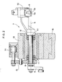
- Fig. 1 is a plan view of a machine for superfinishing annular workpieces, according to an embodiment of the present invention
- Fig. 2 is a view taken in the direction of arrows A - A in Fig. 1.
- the numeral 1 denotes a driving unit having a backing plate 2 attached to the front end of a spindle.
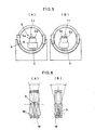
- An annular workpiece W is pressed against the backing plate 2 by pressure rollers 3 and, as shown in Figs. 5A and 5B, it is supported around its periphery by shoes 4 and in this condition it is rotated around a spindle axis a.
- a holder arm 6 holds honing stones 5a and 5b, and a honing stone oscillating means such as honing stone oscillating unit 7, oscillates the honing stones around an oscillating axis b which perpendicularly intersects spindle axis a.
- This honing stone oscillating unit as shown in the sectional view in Fig. 2, comprises an oscillating shaft 8, an oscillating arm 9 connected to one end of said oscillating shaft 8 for oscillating the latter, and a honing stone holder support unit 10 installed at the other end of oscillating unit 7 causes the honing stones 5 to oscillate around the oscillating axis b, as shown in Figs.
- the inner race surface Wi of the annular workpiece W is superfinished to an arcuately curved surface.
- the annular workpiece W whose inner race surface Wi assumes an arcuately curved surface is used as an outer ring for ball bearings.
- the machine of the present invention is applicable to superfinishing of outer rings not only for ball bearings but also for slide ball bearings, conical ⁇ roller bearings, and self-centering roller bearings.
- the oscillating shaft 8 of the oscillating unit 7 may be replaced by a swing mechanism which executes simple harmonic motion in the direction of the spindle axis a or in' a direction which forms a predetermined angle with the spindle axis a.
- the aforesaid oscillating shaft 8 is supported in a sheath 12 through bearings 11, said sheath 12 being slidably held in a sliding block 13.
- the sheath 12 is connected through a connecting rod 15 to a honing stone shifting cylinder 14 mounted on the upper surface of the sliding block 13.
- the honing stone shifting cylinder 14 has a stroke such that it is moved by an amount corresponding to the pitch with which the two honing stones 5a and 5b are juxtaposed on the holder arm 6: thus, by driving this cylinder 14, it is possible to slide the whole of the oscillating unit 7 supported in the sheath 12 to thereby move the honing stones 5a and 5b held on the holder arm 6 in the direction of juxtaposition by an amount corresponding to the pitch of juxtaposition.
- Figs. 5A and 5B show the positions of the honing stones 5a and 5b before and after this movement.
- the sliding block 13 is mounted on a stationary block 16 by being dovetailed to the latter and is slidable by a predetermined amount in a direction parallel to the spindle axis a by means of an index cylinder 17. Such movement of the sliding block 13 is necessary when the annular workpiece W is to be removed from the driving unit 1 upon completion of superfinishing.
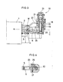
- the aforesaid honing stone support unit 10 as shown in Fig. 3, comprises a support unit outer sleeve 18, an inner sleeve 19 received in said outer sleeve 18, and a piston body 20 received in said inner sleeve 19.
- the inner sleeve 19 is vertically movable with respect to the outer sleeve 18 by injection of air or pressure oil through ports 21 and 22, while the piston body 20- is upwardly urged by a spring 23 and is downwardly movable by injection of air or the like through a port 24 in the upper end of inner sleeve. 19.
- the base end of the holder arm 6 is connected to said inner sleeve 19, and by injecting and discharging air - or the like through the ports 21 and 22, the honing stone 5 can be moved upwardly and down wardly with respect to the honing stone oscillating unit 7.
- the piston-body 20 has a honing stone pressing lever 25 connected thereto, so that downward movement of the piston body 20 causes the lever 25 to press the honing stone 5a or 5b against the inner race surface Wi of the annular workpiece W.
- the lever 25, as shown in Fig. 4, is laterally held between a lever turning piston 26 installed in the lateral wall of the inner sleeve 19 and a spring 27, so that as the turning piston 26 moves forwardly and backwardly, the lever 25 is turned aroung the piston body 20.
- the amount of turning movement is determined so that the front end of the lever 25 is moved by an amount corresponding to the pitch of juxtaposition of the honing stones 5a and 5b. Therefore, with this turning movement it is possible for the lever 25 to selectively press the two honing stones 5a and 5b. According to the aforesaid arrangement, superfinishing of the annular workpiece W can be performed in the following sequence.
- the present invention has the following effects: since, in.superfinishing an annular workpiece, honing stones of different grain sizes can be automatically selectively used on the same station, a single finishing machine is sufficient and there is no need for change of mounting of the annular workpiece in shifting from rough finishing to superfinishing, so that finishing of superfine class can be performed without loss of time.
Landscapes
- Engineering & Computer Science (AREA)
- Mechanical Engineering (AREA)
- Finish Polishing, Edge Sharpening, And Grinding By Specific Grinding Devices (AREA)
Applications Claiming Priority (2)
| Application Number | Priority Date | Filing Date | Title |
|---|---|---|---|
| JP57233000A JPS59115157A (ja) | 1982-12-22 | 1982-12-22 | 環状被加工物の内周面加工用超仕上加工装置 |
| JP233000/82 | 1982-12-22 |
Publications (3)
| Publication Number | Publication Date |
|---|---|
| EP0111936A2 true EP0111936A2 (de) | 1984-06-27 |
| EP0111936A3 EP0111936A3 (en) | 1985-05-15 |
| EP0111936B1 EP0111936B1 (de) | 1988-03-23 |
Family
ID=16948232
Family Applications (1)
| Application Number | Title | Priority Date | Filing Date |
|---|---|---|---|
| EP83112868A Expired EP0111936B1 (de) | 1982-12-22 | 1983-12-21 | Feinschleifmaschine für ringförmige Werkstücke |
Country Status (4)
| Country | Link |
|---|---|
| US (1) | US4534133A (de) |
| EP (1) | EP0111936B1 (de) |
| JP (1) | JPS59115157A (de) |
| DE (1) | DE3376054D1 (de) |
Cited By (1)
| Publication number | Priority date | Publication date | Assignee | Title |
|---|---|---|---|---|
| CN101992409A (zh) * | 2010-09-15 | 2011-03-30 | 上海莱必泰数控机床股份有限公司 | 轴承内外圈磨削加工超精研一体机 |
Families Citing this family (10)
| Publication number | Priority date | Publication date | Assignee | Title |
|---|---|---|---|---|
| DE19804885C5 (de) * | 1998-02-09 | 2004-07-15 | Supfina Grieshaber Gmbh & Co. Kg | Vorrichtung zum Superfinishen |
| KR100408571B1 (ko) * | 2001-05-31 | 2003-12-11 | 오승섭 | 호닝시스템의 지석공급장치 |
| JP5283344B2 (ja) * | 2007-03-29 | 2013-09-04 | Ntn株式会社 | 複列転走面の同時超仕上げ加工装置 |
| CN101301732B (zh) * | 2007-10-10 | 2012-08-08 | 徐秉绶 | 切入式球轴承沟道超精研工艺 |
| DE102011087252B3 (de) * | 2011-11-28 | 2013-01-17 | Supfina Grieshaber Gmbh & Co. Kg | Vorrichtung zur Finishbearbeitung eines insbesondere ringförmigen Werkstücks |
| CN104227546B (zh) * | 2014-08-13 | 2017-04-12 | 无锡市索菲机械电子有限公司 | 一种轴承滚道超精机超精头主轴进、退机构及其使用方法 |
| CN106312557B (zh) * | 2016-08-25 | 2018-12-14 | 施伟红 | 一种用于辊压筒表面进行精细打磨和雕刻的装置 |
| CN108857671B (zh) * | 2018-07-06 | 2020-07-03 | 江苏绿能汽配科技有限公司 | 一种汽车配件加工用打磨装置 |
| CN110774104A (zh) * | 2019-11-05 | 2020-02-11 | 宇环数控机床股份有限公司 | 一种非圆形状零件的浮动打磨设备 |
| CN112454106A (zh) * | 2020-11-18 | 2021-03-09 | 浙江博盟精工轴承有限公司 | 磨超一体机 |
Family Cites Families (14)
| Publication number | Priority date | Publication date | Assignee | Title |
|---|---|---|---|---|
| US174808A (en) * | 1876-03-14 | Improvement in hollow-ware grinders | ||
| US2076601A (en) * | 1935-04-18 | 1937-04-13 | Arthur J Strong | Lapping machine |
| US2141491A (en) * | 1937-08-06 | 1938-12-27 | Fafnir Bearing Co | Lapping device |
| US2350527A (en) * | 1940-11-13 | 1944-06-06 | Micromatic Hone Corp | Adjustable feed for tools |
| US2634561A (en) * | 1948-10-30 | 1953-04-14 | Micromatic Hone Corp | Method of honing grooved elements |
| US3339312A (en) * | 1964-05-18 | 1967-09-05 | Fafnir Bearing Co | Honing apparatus |
| DE1577465A1 (de) * | 1966-01-08 | 1970-04-30 | ||
| US3490179A (en) * | 1967-03-06 | 1970-01-20 | Micromatic Hone Corp | Honing machine |
| US3608244A (en) * | 1968-07-22 | 1971-09-28 | North American Rockwell | Cross raceway lapping of ball bearings |
| DE2326690A1 (de) * | 1973-05-25 | 1974-12-05 | Grieshaber Metallwarenfab Geb | Superfinish-vorrichtung |
| JPS5347690U (de) * | 1976-09-28 | 1978-04-22 | ||
| US4136488A (en) * | 1977-08-29 | 1979-01-30 | Ex-Cell-O Corporation | Honing machine |
| JPS54128897A (en) * | 1978-03-30 | 1979-10-05 | Ntn Toyo Bearing Co Ltd | Superfinishing |
| JPS58109266A (ja) * | 1981-12-23 | 1983-06-29 | Osaka Seiki Kk | 環状被加工物の外周面加工用超仕上加工装置 |
-
1982
- 1982-12-22 JP JP57233000A patent/JPS59115157A/ja active Granted
-
1983
- 1983-12-12 US US06/560,404 patent/US4534133A/en not_active Expired - Lifetime
- 1983-12-21 DE DE8383112868T patent/DE3376054D1/de not_active Expired
- 1983-12-21 EP EP83112868A patent/EP0111936B1/de not_active Expired
Cited By (2)
| Publication number | Priority date | Publication date | Assignee | Title |
|---|---|---|---|---|
| CN101992409A (zh) * | 2010-09-15 | 2011-03-30 | 上海莱必泰数控机床股份有限公司 | 轴承内外圈磨削加工超精研一体机 |
| CN101992409B (zh) * | 2010-09-15 | 2012-05-02 | 上海莱必泰数控机床股份有限公司 | 轴承内外圈磨削加工超精研一体机 |
Also Published As
| Publication number | Publication date |
|---|---|
| EP0111936B1 (de) | 1988-03-23 |
| DE3376054D1 (en) | 1988-04-28 |
| JPS59115157A (ja) | 1984-07-03 |
| US4534133A (en) | 1985-08-13 |
| JPS635222B2 (de) | 1988-02-02 |
| EP0111936A3 (en) | 1985-05-15 |
Similar Documents
| Publication | Publication Date | Title |
|---|---|---|
| US3332172A (en) | Automatic edger | |
| US6419443B2 (en) | Glass product machining apparatus | |
| US4534133A (en) | Machine for superfinishing annular workpieces | |
| CA1081962A (en) | Honing machine | |
| US5551908A (en) | Centerless grinder and wheel truing device therefor | |
| US2807916A (en) | Simultaneous external and internal centerless grinding machine | |
| US4485592A (en) | Machine for superfinishing annular workpieces | |
| US3774349A (en) | Grinding machine | |
| US1988025A (en) | Apparatus for surface finishing the side walls of slots | |
| US2106217A (en) | Machine tool | |
| US2616226A (en) | Apparatus for abrading | |
| US3977126A (en) | Grinding machine | |
| KR200378324Y1 (ko) | 연마기용 조정롤러 | |
| JPH09216150A (ja) | シリンダライナー内面の研削装置 | |
| US3067547A (en) | Ball track honing machine | |
| KR100586562B1 (ko) | 자동연마장치 및 그 제어시스템 | |
| USRE30976E (en) | Honing machine | |
| US3722145A (en) | Machine for grinding of workpieces | |
| US3286407A (en) | Abrasive finishing apparatus | |
| US3657843A (en) | Internal grinding machine | |
| US5117588A (en) | Semi-automatic dressing accessory | |
| KR200377880Y1 (ko) | 자동연마장치 | |
| US3561165A (en) | Universal grinding machine for scissors and shears | |
| JPH06238567A (ja) | ダイヤモンド工具及び研削装置 | |
| KR830002591Y1 (ko) | 회전연마기의 척킹(chucking)장치 |
Legal Events
| Date | Code | Title | Description |
|---|---|---|---|
| PUAI | Public reference made under article 153(3) epc to a published international application that has entered the european phase |
Free format text: ORIGINAL CODE: 0009012 |
|
| 17P | Request for examination filed |
Effective date: 19831221 |
|
| AK | Designated contracting states |
Designated state(s): CH DE FR GB IT LI SE |
|
| PUAL | Search report despatched |
Free format text: ORIGINAL CODE: 0009013 |
|
| AK | Designated contracting states |
Designated state(s): CH DE FR GB IT LI SE |
|
| 17Q | First examination report despatched |
Effective date: 19861010 |
|
| RAP1 | Party data changed (applicant data changed or rights of an application transferred) |
Owner name: OSAKA SEIKI KABUSHIKI KAISHA |
|
| ITF | It: translation for a ep patent filed | ||
| GRAA | (expected) grant |
Free format text: ORIGINAL CODE: 0009210 |
|
| AK | Designated contracting states |
Kind code of ref document: B1 Designated state(s): CH DE FR GB IT LI SE |
|
| REF | Corresponds to: |
Ref document number: 3376054 Country of ref document: DE Date of ref document: 19880428 |
|
| ET | Fr: translation filed | ||
| PLBE | No opposition filed within time limit |
Free format text: ORIGINAL CODE: 0009261 |
|
| STAA | Information on the status of an ep patent application or granted ep patent |
Free format text: STATUS: NO OPPOSITION FILED WITHIN TIME LIMIT |
|
| 26N | No opposition filed | ||
| ITTA | It: last paid annual fee | ||
| EAL | Se: european patent in force in sweden |
Ref document number: 83112868.1 |
|
| REG | Reference to a national code |
Ref country code: GB Ref legal event code: IF02 |
|
| PGFP | Annual fee paid to national office [announced via postgrant information from national office to epo] |
Ref country code: FR Payment date: 20020926 Year of fee payment: 20 |
|
| PGFP | Annual fee paid to national office [announced via postgrant information from national office to epo] |
Ref country code: SE Payment date: 20021108 Year of fee payment: 20 |
|
| PGFP | Annual fee paid to national office [announced via postgrant information from national office to epo] |
Ref country code: GB Payment date: 20021218 Year of fee payment: 20 Ref country code: CH Payment date: 20021218 Year of fee payment: 20 |
|
| PGFP | Annual fee paid to national office [announced via postgrant information from national office to epo] |
Ref country code: DE Payment date: 20030205 Year of fee payment: 20 |
|
| PG25 | Lapsed in a contracting state [announced via postgrant information from national office to epo] |
Ref country code: LI Free format text: LAPSE BECAUSE OF EXPIRATION OF PROTECTION Effective date: 20031220 Ref country code: GB Free format text: LAPSE BECAUSE OF EXPIRATION OF PROTECTION Effective date: 20031220 Ref country code: CH Free format text: LAPSE BECAUSE OF EXPIRATION OF PROTECTION Effective date: 20031220 |
|
| REG | Reference to a national code |
Ref country code: GB Ref legal event code: PE20 |
|
| REG | Reference to a national code |
Ref country code: CH Ref legal event code: PL |
|
| EUG | Se: european patent has lapsed |