EP0112002A2 - Sonde pour détecter le niveau de liquide - Google Patents
Sonde pour détecter le niveau de liquide Download PDFInfo
- Publication number
- EP0112002A2 EP0112002A2 EP83306342A EP83306342A EP0112002A2 EP 0112002 A2 EP0112002 A2 EP 0112002A2 EP 83306342 A EP83306342 A EP 83306342A EP 83306342 A EP83306342 A EP 83306342A EP 0112002 A2 EP0112002 A2 EP 0112002A2
- Authority
- EP
- European Patent Office
- Prior art keywords
- probe
- electrically conductive
- elements
- liquid
- level
- Prior art date
- Legal status (The legal status is an assumption and is not a legal conclusion. Google has not performed a legal analysis and makes no representation as to the accuracy of the status listed.)
- Granted
Links
- 239000007788 liquid Substances 0.000 title claims abstract description 31
- 239000000523 sample Substances 0.000 title claims abstract description 30
- 238000000576 coating method Methods 0.000 claims abstract description 8
- 239000011248 coating agent Substances 0.000 claims abstract description 7
- 230000009969 flowable effect Effects 0.000 claims abstract description 5
- 239000007787 solid Substances 0.000 claims abstract description 5
- 239000000463 material Substances 0.000 claims description 8
- 235000013361 beverage Nutrition 0.000 abstract description 2
- 238000009413 insulation Methods 0.000 description 4
- 230000000694 effects Effects 0.000 description 2
- 230000007613 environmental effect Effects 0.000 description 2
- 239000011810 insulating material Substances 0.000 description 2
- 238000000034 method Methods 0.000 description 2
- 230000005540 biological transmission Effects 0.000 description 1
- 238000010276 construction Methods 0.000 description 1
- 230000001419 dependent effect Effects 0.000 description 1
- 238000001514 detection method Methods 0.000 description 1
- 239000012777 electrically insulating material Substances 0.000 description 1
- 238000005516 engineering process Methods 0.000 description 1
- 238000005429 filling process Methods 0.000 description 1
- 230000002706 hydrostatic effect Effects 0.000 description 1
- 238000005259 measurement Methods 0.000 description 1
- 239000000203 mixture Substances 0.000 description 1
- 239000004810 polytetrafluoroethylene Substances 0.000 description 1
- 229920001343 polytetrafluoroethylene Polymers 0.000 description 1
- 238000004886 process control Methods 0.000 description 1
- 229910001220 stainless steel Inorganic materials 0.000 description 1
- 239000010935 stainless steel Substances 0.000 description 1
- 229920001059 synthetic polymer Polymers 0.000 description 1
Images
Classifications
-
- B—PERFORMING OPERATIONS; TRANSPORTING
- B67—OPENING, CLOSING OR CLEANING BOTTLES, JARS OR SIMILAR CONTAINERS; LIQUID HANDLING
- B67C—CLEANING, FILLING WITH LIQUIDS OR SEMILIQUIDS, OR EMPTYING, OF BOTTLES, JARS, CANS, CASKS, BARRELS, OR SIMILAR CONTAINERS, NOT OTHERWISE PROVIDED FOR; FUNNELS
- B67C3/00—Bottling liquids or semiliquids; Filling jars or cans with liquids or semiliquids using bottling or like apparatus; Filling casks or barrels with liquids or semiliquids
- B67C3/02—Bottling liquids or semiliquids; Filling jars or cans with liquids or semiliquids using bottling or like apparatus
- B67C3/22—Details
- B67C3/28—Flow-control devices, e.g. using valves
- B67C3/282—Flow-control devices, e.g. using valves related to filling level control
- B67C3/285—Flow-control devices, e.g. using valves related to filling level control using liquid contact sensing means
-
- B—PERFORMING OPERATIONS; TRANSPORTING
- B67—OPENING, CLOSING OR CLEANING BOTTLES, JARS OR SIMILAR CONTAINERS; LIQUID HANDLING
- B67C—CLEANING, FILLING WITH LIQUIDS OR SEMILIQUIDS, OR EMPTYING, OF BOTTLES, JARS, CANS, CASKS, BARRELS, OR SIMILAR CONTAINERS, NOT OTHERWISE PROVIDED FOR; FUNNELS
- B67C3/00—Bottling liquids or semiliquids; Filling jars or cans with liquids or semiliquids using bottling or like apparatus; Filling casks or barrels with liquids or semiliquids
- B67C3/02—Bottling liquids or semiliquids; Filling jars or cans with liquids or semiliquids using bottling or like apparatus
- B67C3/22—Details
- B67C3/26—Filling-heads; Means for engaging filling-heads with bottle necks
- B67C2003/2685—Details of probes
Definitions
- This invention relates to a probe for detecting the level of a liquid or of a flowable, pulverulent solid in a container.
- level detecting devices In current process technology, a wide variety of level detecting devices are known and used. The principal types in use are based upon for example electrical conductivity or capacitance; ultrasonic or infrared transmission and reception; and hydrostatic properties (e.g. float switches).
- a probe for detecting the level of a liquid or of a flowable, pulverulent solid in a container which comprises first, second and third elongate, electrically conductive elements all of which are free from direct electrical contact with each other and are disposed substantially in a mutually parallel relationship, the second and third elements being substantially equal in length and being coated with an electrically insulating, liquid-impermeable coating over substantially the whole of their length except for (i) a first region intermediate the ends of the second element and (ii) a second region intermediate the ends of the third element, the mid-points of said first and second regions being spaced from one another in the axial direction; means for applying an electrical potential to said first electrically conductive element; and means for comparing the current flowing through, or the potential difference between, the second and third electrically conductive elements when said electrical potential is applied to the first electrically conductive element.
- the invention will be described hereinafter with reference to its application in measuring liquid levels. It is to be understood, however that the probe of this invention may be used to measure the level of a flowable, pulverulent solid in a container and the description which follows should be read accordingly.
- the three elongate elements can be spaced apart from one another or they may be held closely together; with the latter arrangement, it is essential to prevent direct electrical contact between the elements. They will usually be mutually parallel, but a slight divergence from an exactly parallel relationship is acceptable.
- the second and third elements preferably have the same electrical characteristics and will therefore most conveniently be formed of the same material and fabricated identically (except, of course, for the disposition of said first and second regions). They also are preferably of reasonably rigid construction - e.g. they may take the form of stiff wires.
- the first electrically conductive element can be in the form of an elongate tube open at least at one end and having at least a portion of one of its surfaces coated with an electrically insulating, liquid-impermeable material.
- the first electrically conductive element can be in the form of an elongate plate or grid.
- the second and third electrically conductive elements are conveniently in the form of wires, although they can be in the form of plates or tubes, if desired.
- the second and third electrically conductive elements can conveniently be positioned adjacent to the first electrically conductive element but separated from direct electrical contact therewith.
- the first electrically conductive element is tubular
- the probe as a whole is generally tubular in form, and this is convenient where the probe is to be inserted into containers of liquid, e.g. bottles in a bottle filling process.
- the regions of the second and third electrically conductive elements from which their electrically insulating, liquid-impermeable coatings are removed are at non-equivalent positions along the length of the two elements.
- the two elements are parallel wires
- a region close to the lower part of one of the wires can have its insulation stripped away, while a region close to the central or upper part of the other wire can have its insulation stripped away.
- the two predetermined regions will be non-overlapping in axial extent; this is not essential, however, and some overlapping can be present in certain embodiments of the invention, provided that the two regions are non-equivalent, i.e. their mid-points are spaced from one another in the axial direction.
- the means for applying an electrical potential to the first electrically conductive element is preferably an A.C. source.
- the level which is to be measured affects the electrical response of the second and third electrically conductive elements.
- the electrical response which is monitored can be for example conductivity or capacitance.
- the value of the maximum current will depend on the nature of the liquid in the container and, to a lesser extent, on environmental parameters such as temperature. Because the probe of the invention compares characteristics, e.g. current, between the second and third electrodes, the level detection provided by the probe, and any control functions exercised in response thereto, are independent of the nature of the liquid and of environmental parameters such as temperature. The probe thus compensates automatically for changes which may occur during its use (e.g. changes of temperature or composition) and is not affected by the nature of the liquid whose level is being detected.
- each of the second and third electrically conductive elements is in the form of a wire embedded in the walls -of a tube formed from a suitable electrically insulating material, e.g. a synthetic polymer such as PTFE or PVC. The insulating material is removed from the predetermined regions of the two wires.
- the first electrically conductive element is also embedded in the wall of the tube, and a longitudinal strip of the first electrically conductive element is bared so that it can make electrical contact with a liquid in which the probe is to be placed.
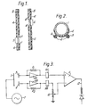
- the second electrically conductive element is in the form of a wire 2 having the greater part of its length covered by an electrically insulating, liquid-impermeable material 4; and the third electrically conductive element is in the form of a wire 3 which also has the majority of its length covered by an electrically insulating, liquid-impermeable material 4.
- a region 5 of the second element is free from coating material 4, and likewise a region 6 of element 3 is tree from coating material 4. These regions 5 and 6 are at non-equivalent positions along the length of the respective elements 2 and 3.
- the length of region 5 is preferably the same as that of region 6, although it is not essential that the two regions should be identical in length.
- the wires 2 and 3 advantageously have the same electrical characteristics, and are preferably stainless steel wires.
- the limits of region 5 are marked 5' and 5", while the limits of region 6 are marked 6' and 6".
- FIG. 2 shows one of the presently preferred embodiments of a probe in accordance with the invention.
- An open-ended, electrically conductive tube 1 constitutes the first electrically conductive element.
- An electrically insulating, liquid-impermeable material 4 coats half of the outer surface of the element 1 over the whole of its length.
- the second and third electrically conductive elements 2 and 3 are held against this layer of insulating material as shown.
- the probe is inserted into a container which is to be filled with an electrically conductive liquid, and an alternating potential is applied to element 1 by appropriate means (not shown). Until the level of liquid within the container reaches the level 5' as shown in Figure 1, no current flows through either of the elements 2 and 3.
- a probe in accordance with this invention will normally be used to effect some degree of process control as a function of the liquid level which it is measuring.
- the region 6 can be located such that it covers a range of levels required in filling a variety of containers, e.g. bottles in the beverage and drinks industry.
- the probe can then be used in conjunction with an electrical comparator circuit to derive a command signal when the liquid level reaches a predetermined point within the region 6, which corresponds to a condition in which the current flowing in element 3 is a predetermined proportion of that flowing in element 2.
- FIG 3 illustrates one example of an electronic circuit for use with the embodiment of the invention described with reference to Figures 1 and 2.
- the circuit comprises a source 7 of alternating potential; operational amplifiers 8a and 8b in parallel with resistors Rl and R2; rectifiers indicated diagrammatically at 9a and 9b; a potentiometer 10; and a comparator .11.
- the circuit components 8a, 9a and Rl are each identical in operation to the circuit components 8b, 9b and R2, respectively.
- the current flowing through the second element 2 reaches its steady, maximum value, i.e. when the liquid completely covers the region 5' to 5", the current is amplified by the operational amplifier 8b and is rectified to direct current by rectifier 9b.
- the potentiometer 10 reduces the amplified current to a pre-set proportion of its original value. As current flows through the element 3, it is likewise amplified by operational amplifier 8a, and rectified to direct current by rectifier 9a. The output from potentiometer 10 and that from rectifier 9a are fed to the input terminals of comparator 11. When the two inputs are equal, an output signal 12 is obtained which can be used as a process command function.
Landscapes
- Filling Of Jars Or Cans And Processes For Cleaning And Sealing Jars (AREA)
- Measurement Of Levels Of Liquids Or Fluent Solid Materials (AREA)
- Automatic Analysis And Handling Materials Therefor (AREA)
- Basic Packing Technique (AREA)
Priority Applications (1)
| Application Number | Priority Date | Filing Date | Title |
|---|---|---|---|
| AT83306342T ATE34369T1 (de) | 1982-10-19 | 1983-10-19 | Sensor zum feststellen der fluessigkeitshoehe. |
Applications Claiming Priority (2)
| Application Number | Priority Date | Filing Date | Title |
|---|---|---|---|
| GB8229889 | 1982-10-19 | ||
| GB8229889 | 1982-10-19 |
Publications (3)
| Publication Number | Publication Date |
|---|---|
| EP0112002A2 true EP0112002A2 (fr) | 1984-06-27 |
| EP0112002A3 EP0112002A3 (en) | 1984-10-31 |
| EP0112002B1 EP0112002B1 (fr) | 1988-05-18 |
Family
ID=10533704
Family Applications (2)
| Application Number | Title | Priority Date | Filing Date |
|---|---|---|---|
| EP83306342A Expired EP0112002B1 (fr) | 1982-10-19 | 1983-10-19 | Sonde pour détecter le niveau de liquide |
| EP83306367A Withdrawn EP0109762A3 (fr) | 1982-10-19 | 1983-10-19 | Dispositif utilisé dans une tête de remplissage |
Family Applications After (1)
| Application Number | Title | Priority Date | Filing Date |
|---|---|---|---|
| EP83306367A Withdrawn EP0109762A3 (fr) | 1982-10-19 | 1983-10-19 | Dispositif utilisé dans une tête de remplissage |
Country Status (4)
| Country | Link |
|---|---|
| US (1) | US4530384A (fr) |
| EP (2) | EP0112002B1 (fr) |
| AT (1) | ATE34369T1 (fr) |
| DE (1) | DE3376644D1 (fr) |
Cited By (3)
| Publication number | Priority date | Publication date | Assignee | Title |
|---|---|---|---|---|
| GB2158948A (en) * | 1984-05-16 | 1985-11-20 | Schlumberger Electronics | Fluid level measurement system |
| GB2180939A (en) * | 1985-09-25 | 1987-04-08 | Partridge Wilson And Company L | Equipment for detecting when the level of a liquid in a container drops below a predetermined level |
| US4905743A (en) * | 1988-11-14 | 1990-03-06 | Gray Alden J | Faucet for filling maple syrup jugs and the like |
Families Citing this family (16)
| Publication number | Priority date | Publication date | Assignee | Title |
|---|---|---|---|---|
| FR2603573B1 (fr) * | 1986-04-18 | 1991-04-19 | Rizo Lopez Juan | Perfectionnements des systemes d'embouteillage automatique |
| BE1000670A5 (fr) * | 1987-06-25 | 1989-03-07 | Baxter Travenol Lab | Dispositif de remplissage de poches a l'aide d'un liquide de perfusion. |
| DE3800379A1 (de) * | 1988-01-08 | 1989-07-20 | Boehringer Mannheim Gmbh | Vorrichtung zum abwaschen der innenflaeche eines reaktionsgefaesses und/oder der aussenflaeche eines reagenzkugelkoerpers |
| DE3806899A1 (de) * | 1988-03-03 | 1989-09-14 | Schering Ag | Ueberwachungssystem fuer das befuellen von behaeltern |
| DE4012155A1 (de) * | 1990-04-14 | 1991-10-17 | Seitz Enzinger Noll Masch | Verfahren zum steuern der fuellelemente einer fuellmaschine und schaltungsanordnung zur durchfuehrung dieses verfahrens |
| DE4102633A1 (de) * | 1990-05-05 | 1991-11-07 | Seitz Enzinger Noll Masch | Fuellelement |
| DE4213738A1 (de) * | 1992-04-25 | 1993-10-28 | Seitz Enzinger Noll Masch | Füllelement für Füllmaschinen zum Füllen von Flaschen o. dgl. Behälter |
| DE4226813C2 (de) * | 1992-08-13 | 1994-08-11 | Kronseder Maschf Krones | Verfahren und Vorrichtung zum Messen des Füllstandes einer Füllflüssigkeit in einem Füllgefäß |
| US5697406A (en) * | 1996-07-12 | 1997-12-16 | Miller Brewing Company | System for detecting missing vent tubes on a bottle filling apparatus |
| US5927350A (en) * | 1997-03-06 | 1999-07-27 | Customized Transportation Inc. | System for preventing spillage from containers during filling thereof |
| DE10044307A1 (de) * | 2000-09-07 | 2002-04-04 | Alfill Engineering Gmbh & Co K | Füllorgan mit Nachtropfverhinderung |
| DE102004011101B4 (de) * | 2004-03-06 | 2011-04-07 | Khs Gmbh | Füllelemente sowie Füllmaschine mit derartigen Füllelementen |
| DE602006006656D1 (de) * | 2006-05-24 | 2009-06-18 | Sidel Holdings & Technology Sa | Ventileinheit für Füllmaschinen mit Füllhöheprobe in isoliertem Rohr |
| EP2539228B8 (fr) * | 2010-01-04 | 2015-05-06 | Dorcia, LLC | Appareil de tube d'evacuation a identification a frequence radio, systeme et procedes pour une detection d'intrusion de tube d'evacuation |
| US20150191260A1 (en) * | 2010-01-04 | 2015-07-09 | Grant Cook | Vent tube apparatus, system and methods with traceable cap for vent tube intrusion detection |
| WO2021126532A1 (fr) | 2019-12-03 | 2021-06-24 | Dorcia, Llc | Appareil, système et procédés de dispositif de remplissage pour la détection d'intrusion |
Family Cites Families (12)
| Publication number | Priority date | Publication date | Assignee | Title |
|---|---|---|---|---|
| US3461446A (en) * | 1965-07-02 | 1969-08-12 | Scully Signal Corp | Fluid-level detecting apparatus |
| DE2112121A1 (de) * | 1971-03-13 | 1972-09-21 | Tornado Gmbh | Vorrichtung zur Regelung des Fluessigkeitsstandes in einem Behaelter |
| US3862571A (en) * | 1973-08-06 | 1975-01-28 | Agridustrial Electronics | Multielectrode capacitive liquid level sensing system |
| GB1544416A (en) * | 1975-10-08 | 1979-04-19 | Molins Ltd | Apparatus for feeding tobacco or similar particulate material in a uniform stream |
| DE2728283C2 (de) * | 1977-06-23 | 1982-04-29 | Siemens AG, 1000 Berlin und 8000 München | Vorrichtung zur Überwachung des Tintenvorrates in Tintenschreibeinrichtungen |
| DE2749547C2 (de) * | 1977-11-05 | 1979-10-18 | Gustav F. Gerdts Kg, 2800 Bremen | Sonde zur kontinuierlichen Niveaumessung |
| DE3001099A1 (de) * | 1980-01-14 | 1981-07-23 | Seitz-Werke Gmbh, 6550 Bad Kreuznach | Fuellelement fuer gegendruck-fuellmaschinen |
| DE3008386C2 (de) * | 1980-03-05 | 1986-01-16 | Seitz Enzinger Noll Maschinenbau Ag, 6800 Mannheim | Füllelement für Gegendruck-Füllmaschinen |
| DE3009405C2 (de) * | 1980-03-12 | 1985-01-17 | Seitz Enzinger Noll Maschinenbau Ag, 6800 Mannheim | Verfahren und Anordnung zum Steuern von Füllelementen in Füllmaschinen |
| DE3015132C2 (de) * | 1980-04-19 | 1982-08-19 | Seitz-Werke Gmbh, 6550 Bad Kreuznach | Füllelement für Gegendruck-Füllmaschinen mit Füllrohr |
| GB2084322B (en) * | 1980-09-18 | 1984-08-30 | Avery Hardoll Ltd | Fluid measuring system |
| GB2094003B (en) * | 1981-03-03 | 1984-10-24 | Kirk Alan | Detecting the level of an electrically conductive liquid |
-
1983
- 1983-10-19 EP EP83306342A patent/EP0112002B1/fr not_active Expired
- 1983-10-19 AT AT83306342T patent/ATE34369T1/de not_active IP Right Cessation
- 1983-10-19 DE DE8383306342T patent/DE3376644D1/de not_active Expired
- 1983-10-19 US US06/543,587 patent/US4530384A/en not_active Expired - Fee Related
- 1983-10-19 EP EP83306367A patent/EP0109762A3/fr not_active Withdrawn
Cited By (3)
| Publication number | Priority date | Publication date | Assignee | Title |
|---|---|---|---|---|
| GB2158948A (en) * | 1984-05-16 | 1985-11-20 | Schlumberger Electronics | Fluid level measurement system |
| GB2180939A (en) * | 1985-09-25 | 1987-04-08 | Partridge Wilson And Company L | Equipment for detecting when the level of a liquid in a container drops below a predetermined level |
| US4905743A (en) * | 1988-11-14 | 1990-03-06 | Gray Alden J | Faucet for filling maple syrup jugs and the like |
Also Published As
| Publication number | Publication date |
|---|---|
| EP0112002A3 (en) | 1984-10-31 |
| US4530384A (en) | 1985-07-23 |
| ATE34369T1 (de) | 1988-06-15 |
| DE3376644D1 (en) | 1988-06-23 |
| EP0112002B1 (fr) | 1988-05-18 |
| EP0109762A2 (fr) | 1984-05-30 |
| EP0109762A3 (fr) | 1985-07-24 |
Similar Documents
| Publication | Publication Date | Title |
|---|---|---|
| EP0112002A2 (fr) | Sonde pour détecter le niveau de liquide | |
| US4389900A (en) | Capacitance probe sensor device | |
| CA2017833C (fr) | Capteur dielectrique interdigite planar | |
| CA1069996A (fr) | Appareil generateur d'un signal electrique indicateur de niveau de liquide | |
| US3153342A (en) | Fluent material level measuring apparatus and method of manufacturing the same | |
| US3710244A (en) | Capacitance probe for detecting moisture with very long cables | |
| RU97117939A (ru) | Матричный датчик для обнаружения аналитов в жидкостях | |
| CA2088240A1 (fr) | Appareil et methodes de mesure des caracteristiques dielectriques et geometriques des materiaux | |
| IL106829A (en) | Soil moisture sensor | |
| US4188826A (en) | Device for measuring the liquid level of an electrically conductive liquid | |
| KR20010087119A (ko) | 저항성 유체 레벨 감지 및 제어 시스템 | |
| JPH0674994B2 (ja) | 容量性液体感知器 | |
| EP0575312A4 (fr) | Detecteur de niveau et de compositions de liquides et procede. | |
| US4515015A (en) | Capacitance level sensor for use with viscous, electrically conductive materials | |
| JPS6144324A (ja) | 流体レベル測定装置 | |
| US4301681A (en) | Method of using capacitor probe with a semiconductive electrode | |
| US3520638A (en) | Means and apparatus for sensing and controlling material levels | |
| US2894390A (en) | Liquid level sensing means | |
| USRE32019E (en) | Methods of and/or means for indicating the levels of liquids | |
| US4428026A (en) | Two layer probe | |
| WO1993000573A1 (fr) | Detecteur de niveau d'interface | |
| US4885529A (en) | Identification of fluids and an interface between fluids by measuring complex impedance | |
| US2930232A (en) | Device for manifesting thermal boundaries | |
| US3593119A (en) | Electronic titrimeter | |
| US2541576A (en) | Apparatus for determining fluent level |
Legal Events
| Date | Code | Title | Description |
|---|---|---|---|
| PUAI | Public reference made under article 153(3) epc to a published international application that has entered the european phase |
Free format text: ORIGINAL CODE: 0009012 |
|
| AK | Designated contracting states |
Designated state(s): AT BE CH DE FR GB IT LI LU NL SE |
|
| PUAL | Search report despatched |
Free format text: ORIGINAL CODE: 0009013 |
|
| AK | Designated contracting states |
Designated state(s): AT BE CH DE FR GB IT LI LU NL SE |
|
| 17P | Request for examination filed |
Effective date: 19850418 |
|
| 17Q | First examination report despatched |
Effective date: 19860129 |
|
| GRAA | (expected) grant |
Free format text: ORIGINAL CODE: 0009210 |
|
| AK | Designated contracting states |
Kind code of ref document: B1 Designated state(s): AT BE CH DE FR GB IT LI LU NL SE |
|
| PG25 | Lapsed in a contracting state [announced via postgrant information from national office to epo] |
Ref country code: NL Effective date: 19880518 Ref country code: LI Effective date: 19880518 Ref country code: IT Free format text: LAPSE BECAUSE OF FAILURE TO SUBMIT A TRANSLATION OF THE DESCRIPTION OR TO PAY THE FEE WITHIN THE PRESCRIBED TIME-LIMIT;WARNING: LAPSES OF ITALIAN PATENTS WITH EFFECTIVE DATE BEFORE 2007 MAY HAVE OCCURRED AT ANY TIME BEFORE 2007. THE CORRECT EFFECTIVE DATE MAY BE DIFFERENT FROM THE ONE RECORDED. Effective date: 19880518 Ref country code: FR Free format text: THE PATENT HAS BEEN ANNULLED BY A DECISION OF A NATIONAL AUTHORITY Effective date: 19880518 Ref country code: CH Effective date: 19880518 Ref country code: BE Effective date: 19880518 Ref country code: AT Effective date: 19880518 |
|
| REF | Corresponds to: |
Ref document number: 34369 Country of ref document: AT Date of ref document: 19880615 Kind code of ref document: T |
|
| PG25 | Lapsed in a contracting state [announced via postgrant information from national office to epo] |
Ref country code: SE Effective date: 19880531 |
|
| REF | Corresponds to: |
Ref document number: 3376644 Country of ref document: DE Date of ref document: 19880623 |
|
| REG | Reference to a national code |
Ref country code: CH Ref legal event code: PL |
|
| EN | Fr: translation not filed | ||
| NLV1 | Nl: lapsed or annulled due to failure to fulfill the requirements of art. 29p and 29m of the patents act | ||
| PG25 | Lapsed in a contracting state [announced via postgrant information from national office to epo] |
Ref country code: LU Free format text: LAPSE BECAUSE OF NON-PAYMENT OF DUE FEES Effective date: 19881031 |
|
| PLBE | No opposition filed within time limit |
Free format text: ORIGINAL CODE: 0009261 |
|
| STAA | Information on the status of an ep patent application or granted ep patent |
Free format text: STATUS: NO OPPOSITION FILED WITHIN TIME LIMIT |
|
| 26N | No opposition filed | ||
| PG25 | Lapsed in a contracting state [announced via postgrant information from national office to epo] |
Ref country code: DE Effective date: 19890701 |
|
| PGFP | Annual fee paid to national office [announced via postgrant information from national office to epo] |
Ref country code: GB Payment date: 19900418 Year of fee payment: 7 |
|
| PG25 | Lapsed in a contracting state [announced via postgrant information from national office to epo] |
Ref country code: GB Effective date: 19901019 |
|
| GBPC | Gb: european patent ceased through non-payment of renewal fee |