EP0112011A2 - Lager für Zahnradpumpe - Google Patents
Lager für Zahnradpumpe Download PDFInfo
- Publication number
- EP0112011A2 EP0112011A2 EP83306612A EP83306612A EP0112011A2 EP 0112011 A2 EP0112011 A2 EP 0112011A2 EP 83306612 A EP83306612 A EP 83306612A EP 83306612 A EP83306612 A EP 83306612A EP 0112011 A2 EP0112011 A2 EP 0112011A2
- Authority
- EP
- European Patent Office
- Prior art keywords
- recess
- bush
- bore
- zone
- passage
- Prior art date
- Legal status (The legal status is an assumption and is not a legal conclusion. Google has not performed a legal analysis and makes no representation as to the accuracy of the status listed.)
- Granted
Links
Images

Classifications
-
- F—MECHANICAL ENGINEERING; LIGHTING; HEATING; WEAPONS; BLASTING
- F16—ENGINEERING ELEMENTS AND UNITS; GENERAL MEASURES FOR PRODUCING AND MAINTAINING EFFECTIVE FUNCTIONING OF MACHINES OR INSTALLATIONS; THERMAL INSULATION IN GENERAL
- F16C—SHAFTS; FLEXIBLE SHAFTS; ELEMENTS OR CRANKSHAFT MECHANISMS; ROTARY BODIES OTHER THAN GEARING ELEMENTS; BEARINGS
- F16C33/00—Parts of bearings; Special methods for making bearings or parts thereof
- F16C33/02—Parts of sliding-contact bearings
- F16C33/04—Brasses; Bushes; Linings
- F16C33/06—Sliding surface mainly made of metal
- F16C33/10—Construction relative to lubrication
- F16C33/1025—Construction relative to lubrication with liquid, e.g. oil, as lubricant
- F16C33/106—Details of distribution or circulation inside the bearings, e.g. details of the bearing surfaces to affect flow or pressure of the liquid
-
- F—MECHANICAL ENGINEERING; LIGHTING; HEATING; WEAPONS; BLASTING
- F01—MACHINES OR ENGINES IN GENERAL; ENGINE PLANTS IN GENERAL; STEAM ENGINES
- F01C—ROTARY-PISTON OR OSCILLATING-PISTON MACHINES OR ENGINES
- F01C21/00—Component parts, details or accessories not provided for in groups F01C1/00 - F01C20/00
- F01C21/02—Arrangements of bearings
-
- F—MECHANICAL ENGINEERING; LIGHTING; HEATING; WEAPONS; BLASTING
- F04—POSITIVE - DISPLACEMENT MACHINES FOR LIQUIDS; PUMPS FOR LIQUIDS OR ELASTIC FLUIDS
- F04C—ROTARY-PISTON, OR OSCILLATING-PISTON, POSITIVE-DISPLACEMENT MACHINES FOR LIQUIDS; ROTARY-PISTON, OR OSCILLATING-PISTON, POSITIVE-DISPLACEMENT PUMPS
- F04C15/00—Component parts, details or accessories of machines, pumps or pumping installations, not provided for in groups F04C2/00 - F04C14/00
- F04C15/0042—Systems for the equilibration of forces acting on the machines or pump
-
- F—MECHANICAL ENGINEERING; LIGHTING; HEATING; WEAPONS; BLASTING
- F04—POSITIVE - DISPLACEMENT MACHINES FOR LIQUIDS; PUMPS FOR LIQUIDS OR ELASTIC FLUIDS
- F04C—ROTARY-PISTON, OR OSCILLATING-PISTON, POSITIVE-DISPLACEMENT MACHINES FOR LIQUIDS; ROTARY-PISTON, OR OSCILLATING-PISTON, POSITIVE-DISPLACEMENT PUMPS
- F04C2240/00—Components
- F04C2240/50—Bearings
- F04C2240/54—Hydrostatic or hydrodynamic bearing assemblies specially adapted for rotary positive displacement pumps or compressors
-
- F—MECHANICAL ENGINEERING; LIGHTING; HEATING; WEAPONS; BLASTING
- F04—POSITIVE - DISPLACEMENT MACHINES FOR LIQUIDS; PUMPS FOR LIQUIDS OR ELASTIC FLUIDS
- F04C—ROTARY-PISTON, OR OSCILLATING-PISTON, POSITIVE-DISPLACEMENT MACHINES FOR LIQUIDS; ROTARY-PISTON, OR OSCILLATING-PISTON, POSITIVE-DISPLACEMENT PUMPS
- F04C2240/00—Components
- F04C2240/50—Bearings
- F04C2240/56—Bearing bushings or details thereof
Definitions
- This invention relates to bearing bushes for use in external gear pumps, that is pumps in which liquid is displaced by the action of two externally meshed toothed gears.
- the precise area of load concentration may vary with changes in operating conditions of the pump, but remains within a zone, hereinafter referred to as the critical zone, which lies generally at the first quadrant, relative to the direction of gear rotation, from a plane which includes the axes of the meshing gears.
- This critical zone can readily be observed in a bush which has been dismantled from a normally operated pump. It has been proposed to provide a recess in the bore within the critical zone and to supply this recess with liquid from the pump outlet. Thereby providing a hydrostatic bearing to support the concentrated load and to assist in dissipation of heat.
- this passage may comprise a groove, which extends along the bore of the bush and opens on to its end faces.
- a bearing bush for a gear pump said bush having within its bore a first recess which lies wholly within a critical zone of the bore, as hereinbefore defined, a first passage for supplying liquid under pressure to said first recess, a second recess in said bore, and a second passage through which fluid can flow from said bore to a zone of reduced pressure, said second recess and said second passage lying wholly outside said critical zone.
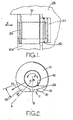
- a bush 10 for a driven gear is shown in Figures 1 and 2.
- a generally similar bush 10A for a meshing driving gear abuts the gear 10 in a known manner.
- the bush 10 is generally cylindrical but is provided with a flat 11 which, in use, abuts a corresponding flat on the bush 10A.
- the line B-B indicates a plane which includes the axes of the two bushes 10, 10A for meshing gears.
- the bush 10 is provided with cut-outs 12, 13 which respectively communicate with the pump inlet and outlet. Pressure in the pump outlet and reaction between the meshing gear teeth results in a force on a shaft of a gear within the bush 10. The line of action of this force is indicated at 14 and is inclined at 60° to the plane B-B.
- This zone 15 lies generally in the area of the first quadrant, in the direction of rotation R of a gear within the pump, measured from the plane B-B.
- the zone 15 may be considered as lying between 20° and 100° from the line B-B in the direction of rotation R.
- the zone 15 has a circumferential extent of approximately 20°, and in the described example extends between 50° and 70° from the plane B-B, for the bush 10 of the driven gear, and between 40° and 60° from that plane in the bush 10A of the driving gear.
- a recess 17 Within the bore 16 of the bush is a recess 17 whose length is less than the axial dimension of the bush and which is centred on the mean line of action 14.
- the recess 17 communicates through a first passage 18 with the cut-out 13 so that, in use, high pressure liquid from the pump outlet is supplied to the recess 17 and provides a hydrostatic bearing adjacent the area of concentrated load.
- the recess 17 overlaps the critical zone 15, and in the specific example extends between 55° and 80° from the plane B-B.
- the axial length of the recess 17 is approximately 70% of that of the bore 16, to provide an adequate restriction to flow between the recess 17 and the end faces of the bush 10.
- the recess 17 has a depth of 1.5 mm. In alternative embodiments the recess 17 may have a circumferential extent of between 20° and 40°.
- a further recess 20 in the bore 16 has an axial extent equal to that of the recess 17 but lies wholly outside the critical zone 15. Fluid entering the recess 20 provides a reservoir from which liquid can flow to any transient low pressure zone occurring within the bore 16 as a result of relative movement of the gear axle. Cavitation within the transient low pressure zones is thereby prevented and it has been found that erosion of the bore 16 is virtually eradicated, even following severe tests in which a pump having bushes according to the invention was operated with deliberately mutilated gear teeth.
- An end 21 of the recess 20 is spaced by not less than 15° from the closest part of the zone 15. Alternatively, if an adjacent end 22 of the recess 17 lies outside the critical zone 15, the end 21 of the recess 20 willbe spaced by not less than 15° from the end 22 of the recess 17.
- the circumferential extent of the recess 20 is in the present example 160°, but may be between 130° and 190°.
- the axial extent of the recess is not greater than 70% of the bearing surface of the bore 16, so that if the load of the gear axle is transiently shifted to a direction generally opposite to the line of action 14, the zones of the bore 16 at the ends of the recess 20 will adequately support that load.
- the depth of the recess 20 is 1.5 mm.
- a second passage is constituted by a V-groove 23 which is located approximately 30° from the plane B-B in a direction opposite to the direction of rotation R.
- the groove 23 opens on to the end faces of the bush 10.
- the groove 23 is interrupted by the recess 20, but in other embodiments the groove 23 and recess 20 may be separate.
- the groove 23 has two functions, one of which is to supply fluid to the recess 20 from a zone within a counterbore 24 ( Figure 1) in the bush 10 adjacent the end face of the gear therein. Fluid flowing from the counterbore 24 to a zone 27 of reduced pressure within the pump housing 25. This flow prevents excessive increase in the pressure in the zone 24 and also serves to maintain the recess 20 full of fluid. In embodiments where the groove 23 and recess 20 are separate, only the latter function is performed by the groove 23.
Landscapes
- Engineering & Computer Science (AREA)
- General Engineering & Computer Science (AREA)
- Mechanical Engineering (AREA)
- Chemical & Material Sciences (AREA)
- Oil, Petroleum & Natural Gas (AREA)
- Rotary Pumps (AREA)
Applications Claiming Priority (2)
| Application Number | Priority Date | Filing Date | Title |
|---|---|---|---|
| GB8232053 | 1982-11-10 | ||
| GB8232053 | 1982-11-10 |
Publications (3)
| Publication Number | Publication Date |
|---|---|
| EP0112011A2 true EP0112011A2 (de) | 1984-06-27 |
| EP0112011A3 EP0112011A3 (en) | 1985-08-28 |
| EP0112011B1 EP0112011B1 (de) | 1987-09-16 |
Family
ID=10534153
Family Applications (1)
| Application Number | Title | Priority Date | Filing Date |
|---|---|---|---|
| EP83306612A Expired EP0112011B1 (de) | 1982-11-10 | 1983-10-31 | Lager für Zahnradpumpe |
Country Status (3)
| Country | Link |
|---|---|
| US (1) | US4573889A (de) |
| EP (1) | EP0112011B1 (de) |
| DE (1) | DE3373692D1 (de) |
Cited By (3)
| Publication number | Priority date | Publication date | Assignee | Title |
|---|---|---|---|---|
| EP0410074A3 (en) * | 1989-07-28 | 1991-10-09 | Kabushiki Kaisha Kobe Seiko Sho Also Known As Kobe Steel Ltd. | Radial load reducing device, and sliding bearing and screw compressor using the device |
| GB2529030A (en) * | 2014-06-06 | 2016-02-10 | Hamilton Sundstrand Corp | Gear pump driven gear stationary bearing |
| WO2017066456A1 (en) * | 2015-10-14 | 2017-04-20 | Eaton Corporation | Gear pump journal bearing lubrication flow feed |
Families Citing this family (6)
| Publication number | Priority date | Publication date | Assignee | Title |
|---|---|---|---|---|
| GB8723129D0 (en) * | 1987-10-02 | 1987-11-04 | Lucas Ind Plc | Bearings for gear pumps |
| NL8803199A (nl) * | 1988-12-29 | 1990-07-16 | Skf Ind Trading & Dev | Schroefcompressor. |
| US6179594B1 (en) | 1999-05-03 | 2001-01-30 | Dynisco, Inc. | Air-cooled shaft seal |
| US6213745B1 (en) | 1999-05-03 | 2001-04-10 | Dynisco | High-pressure, self-lubricating journal bearings |
| JP2011214588A (ja) * | 2010-03-31 | 2011-10-27 | Kyocera Mita Corp | 駆動伝達機構及びそれを備えた画像形成装置 |
| US12247617B2 (en) | 2022-12-08 | 2025-03-11 | Hamilton Sundstrand Corporation | Cavitation resistant journal bearing |
Family Cites Families (13)
| Publication number | Priority date | Publication date | Assignee | Title |
|---|---|---|---|---|
| FR888982A (fr) * | 1942-12-09 | 1943-12-28 | Outil R B V L | Procédé et dispositif pour l'équilibrage des pompes à engrenage |
| US2479077A (en) * | 1945-07-23 | 1949-08-16 | Webster Electric Co Inc | Balanced hydraulic pump or motor |
| US2891483A (en) * | 1956-04-13 | 1959-06-23 | Thompson Ramo Wooldridge Inc | Movable bushing for pressure loaded gear pumps |
| GB795647A (en) * | 1957-01-04 | 1958-05-28 | Glacier Co Ltd | Improvements in or relating to plain bearings |
| FR1190870A (fr) * | 1957-01-31 | 1959-10-15 | Glacier Co Ltd | Palier lisse, notamment pour moteurs |
| US3053192A (en) * | 1960-03-01 | 1962-09-11 | Bosch Gmbh Robert | Bearing arrangement for a hydraulic machine |
| DE1264958B (de) * | 1960-10-08 | 1968-03-28 | Bosch Gmbh Robert | Zahnradpumpe oder -motor |
| IT712750A (de) * | 1963-12-03 | |||
| GB1131714A (en) * | 1965-05-06 | 1968-10-23 | Lucas Industries Ltd | Bearings |
| US3528756A (en) * | 1968-12-04 | 1970-09-15 | Borg Warner | Pressure loaded pump |
| US3671155A (en) * | 1970-04-13 | 1972-06-20 | Case Co J I | Hydrostatic bearing |
| GB1554262A (en) * | 1975-06-24 | 1979-10-17 | Kayaba Industry Co Ltd | Gear pump |
| US4289460A (en) * | 1979-06-28 | 1981-09-15 | Chandler Evans Inc. | Bearing lubrication system for gear pump having clearance between bearing and housing wall for preventing entry of contaminants larger than lubrication passage |
-
1983
- 1983-10-31 DE DE8383306612T patent/DE3373692D1/de not_active Expired
- 1983-10-31 EP EP83306612A patent/EP0112011B1/de not_active Expired
- 1983-11-07 US US06/549,680 patent/US4573889A/en not_active Expired - Fee Related
Cited By (7)
| Publication number | Priority date | Publication date | Assignee | Title |
|---|---|---|---|---|
| EP0410074A3 (en) * | 1989-07-28 | 1991-10-09 | Kabushiki Kaisha Kobe Seiko Sho Also Known As Kobe Steel Ltd. | Radial load reducing device, and sliding bearing and screw compressor using the device |
| GB2529030A (en) * | 2014-06-06 | 2016-02-10 | Hamilton Sundstrand Corp | Gear pump driven gear stationary bearing |
| US9488174B2 (en) | 2014-06-06 | 2016-11-08 | Hamilton Sundstrand Corporation | Gear pump driven gear stationary bearing |
| GB2529030B (en) * | 2014-06-06 | 2017-05-31 | Hamilton Sundstrand Corp | Gear pump driven gear stationary bearing |
| WO2017066456A1 (en) * | 2015-10-14 | 2017-04-20 | Eaton Corporation | Gear pump journal bearing lubrication flow feed |
| GB2558152A (en) * | 2015-10-14 | 2018-07-04 | Eaton Intelligent Power Ltd | Gear pump journal bearing lubrication flow feed |
| GB2558152B (en) * | 2015-10-14 | 2021-07-07 | Eaton Intelligent Power Ltd | Gear pump journal bearing lubrication flow feed |
Also Published As
| Publication number | Publication date |
|---|---|
| DE3373692D1 (en) | 1987-10-22 |
| US4573889A (en) | 1986-03-04 |
| EP0112011B1 (de) | 1987-09-16 |
| EP0112011A3 (en) | 1985-08-28 |
Similar Documents
| Publication | Publication Date | Title |
|---|---|---|
| EP0037210B1 (de) | Zur Hochdruckseite pumpende Dichtungskombination | |
| EP0112011B1 (de) | Lager für Zahnradpumpe | |
| ATE184080T1 (de) | Schrägverzahnte zahnradpumpe oder-motor | |
| EP0349574A1 (de) | Schraubenrotormaschine. | |
| US2276107A (en) | Gear pump | |
| US3371615A (en) | Pressure loaded pump | |
| US3473476A (en) | Gear pump seal | |
| US3779674A (en) | High-pressure gear pump | |
| KR940001627B1 (ko) | 반경부하 감소장치, 및 이 장치를 사용한 슬라이딩 베어링 및 스크루 컴프레서 | |
| EP0310292A2 (de) | Lagerfutter für eine Zahnradpumpe | |
| GB1151123A (en) | Improvements in or relating to Internally Meshing Gear Pumps. | |
| US4242064A (en) | Rotary fluid pump with eccentrically moving pumping sleeve | |
| WO1981001315A1 (en) | Contaminant resistant gear pumps and motors | |
| US6692244B2 (en) | Hydraulic pump utilizing floating shafts | |
| US3966367A (en) | Hydraulic motor or pump with movable wedge | |
| US3263620A (en) | Light weight bearings for gear pumps | |
| US5322428A (en) | Gear transfer pump with lubrication and sealing of the driveshaft and idler pin | |
| US4330241A (en) | Gear pump with pressure loaded bearing blocks and separate gear sealing plates | |
| GB1566514A (en) | Hydraulic meshing-screw machine | |
| US3781149A (en) | Rotary fluid-pressure machines | |
| KR100526767B1 (ko) | 닫힌 유압회로에서의 역전조작을 위한 내치 기어 장치 | |
| RU2100655C1 (ru) | Шестеренная гидромашина | |
| US3598455A (en) | Hydrostatic bearing system | |
| RU2037658C1 (ru) | Шестеренная гидромашина | |
| US3836295A (en) | Temperature compensated gear pump with travel limited wearblock |
Legal Events
| Date | Code | Title | Description |
|---|---|---|---|
| PUAI | Public reference made under article 153(3) epc to a published international application that has entered the european phase |
Free format text: ORIGINAL CODE: 0009012 |
|
| AK | Designated contracting states |
Designated state(s): DE FR GB IT |
|
| PUAL | Search report despatched |
Free format text: ORIGINAL CODE: 0009013 |
|
| RHK1 | Main classification (correction) |
Ipc: F01C 21/02 |
|
| AK | Designated contracting states |
Designated state(s): DE FR GB IT |
|
| 17P | Request for examination filed |
Effective date: 19860205 |
|
| 17Q | First examination report despatched |
Effective date: 19860825 |
|
| GRAA | (expected) grant |
Free format text: ORIGINAL CODE: 0009210 |
|
| AK | Designated contracting states |
Kind code of ref document: B1 Designated state(s): DE FR GB IT |
|
| PG25 | Lapsed in a contracting state [announced via postgrant information from national office to epo] |
Ref country code: IT Free format text: LAPSE BECAUSE OF FAILURE TO SUBMIT A TRANSLATION OF THE DESCRIPTION OR TO PAY THE FEE WITHIN THE PRESCRIBED TIME-LIMIT;WARNING: LAPSES OF ITALIAN PATENTS WITH EFFECTIVE DATE BEFORE 2007 MAY HAVE OCCURRED AT ANY TIME BEFORE 2007. THE CORRECT EFFECTIVE DATE MAY BE DIFFERENT FROM THE ONE RECORDED. Effective date: 19870916 Ref country code: FR Free format text: THE PATENT HAS BEEN ANNULLED BY A DECISION OF A NATIONAL AUTHORITY Effective date: 19870916 |
|
| REF | Corresponds to: |
Ref document number: 3373692 Country of ref document: DE Date of ref document: 19871022 |
|
| EN | Fr: translation not filed | ||
| PG25 | Lapsed in a contracting state [announced via postgrant information from national office to epo] |
Ref country code: DE Effective date: 19880701 |
|
| PLBE | No opposition filed within time limit |
Free format text: ORIGINAL CODE: 0009261 |
|
| STAA | Information on the status of an ep patent application or granted ep patent |
Free format text: STATUS: NO OPPOSITION FILED WITHIN TIME LIMIT |
|
| 26N | No opposition filed | ||
| PGFP | Annual fee paid to national office [announced via postgrant information from national office to epo] |
Ref country code: GB Payment date: 19900905 Year of fee payment: 8 |
|
| PG25 | Lapsed in a contracting state [announced via postgrant information from national office to epo] |
Ref country code: GB Effective date: 19911031 |
|
| GBPC | Gb: european patent ceased through non-payment of renewal fee |