EP0112014B1 - Appareil pour la lecture de codes à barres - Google Patents
Appareil pour la lecture de codes à barres Download PDFInfo
- Publication number
- EP0112014B1 EP0112014B1 EP83306692A EP83306692A EP0112014B1 EP 0112014 B1 EP0112014 B1 EP 0112014B1 EP 83306692 A EP83306692 A EP 83306692A EP 83306692 A EP83306692 A EP 83306692A EP 0112014 B1 EP0112014 B1 EP 0112014B1
- Authority
- EP
- European Patent Office
- Prior art keywords
- bar
- bar code
- signal
- sensing devices
- signals
- Prior art date
- Legal status (The legal status is an assumption and is not a legal conclusion. Google has not performed a legal analysis and makes no representation as to the accuracy of the status listed.)
- Expired
Links
Images



Classifications
-
- G—PHYSICS
- G06—COMPUTING OR CALCULATING; COUNTING
- G06K—GRAPHICAL DATA READING; PRESENTATION OF DATA; RECORD CARRIERS; HANDLING RECORD CARRIERS
- G06K7/00—Methods or arrangements for sensing record carriers, e.g. for reading patterns
- G06K7/10—Methods or arrangements for sensing record carriers, e.g. for reading patterns by electromagnetic radiation, e.g. optical sensing; by corpuscular radiation
- G06K7/10544—Methods or arrangements for sensing record carriers, e.g. for reading patterns by electromagnetic radiation, e.g. optical sensing; by corpuscular radiation by scanning of the records by radiation in the optical part of the electromagnetic spectrum
- G06K7/10821—Methods or arrangements for sensing record carriers, e.g. for reading patterns by electromagnetic radiation, e.g. optical sensing; by corpuscular radiation by scanning of the records by radiation in the optical part of the electromagnetic spectrum further details of bar or optical code scanning devices
- G06K7/10851—Circuits for pulse shaping, amplifying, eliminating noise signals, checking the function of the sensing device
-
- G—PHYSICS
- G06—COMPUTING OR CALCULATING; COUNTING
- G06K—GRAPHICAL DATA READING; PRESENTATION OF DATA; RECORD CARRIERS; HANDLING RECORD CARRIERS
- G06K7/00—Methods or arrangements for sensing record carriers, e.g. for reading patterns
- G06K7/10—Methods or arrangements for sensing record carriers, e.g. for reading patterns by electromagnetic radiation, e.g. optical sensing; by corpuscular radiation
- G06K7/14—Methods or arrangements for sensing record carriers, e.g. for reading patterns by electromagnetic radiation, e.g. optical sensing; by corpuscular radiation using light without selection of wavelength, e.g. sensing reflected white light
Definitions
- the present invention relates to an apparatus for reading bar codes on documents such as checks, and in particular for reading coded bars each composed of a number of dots.
- optical bar codes printed on financial documents is well-established in the banking industry and in processing of such documents optical readers are employed. Ideally, the presence of a bar would be indicated by one of two states, and the absence of a bar would be indicated by the other of two states.
- reliability in reading is a critical requirement. Due to limitations in printing the bars on documents, during which ink splatter and smudging of the bar occurs, prior bar code readers have been unable to process the document with the desired reliability. Other problems encountered in reading these documents include endorsement indicia stamped by the bank over the bar code, the color and quality of the paper and the presence of a design printed on the document on which the bar code is printed.
- a bar code reader capable of reading bar codes comprising a row of dots is disclosed in US-A-3784705.
- a laser beam is arranged to scan a label in a direction perpendicular to the rows of dots to produce analog signals from the scanner which are digitized and decoded for delivery to a processor.
- a danger with an arrangement of this kind is that the narrow scanning beam of the laser may move wholly within a gap or rows of gaps between the dots of the bars causing erroneous readings.
- the above- mentioned U.S. patent tries to avoid such errors by diffusing the laser beam so that it will be broader than the gaps between the dots. While this alleviates the above problem poorly printed bars or missing dots in a bar could still result in erroneous readings.
- a bar code reader for reading a bar code printed on a document and consisting of a plurality of bars, said reader including a linear array of sensing devices for sensing a bar, each sensing device being arranged to produce an analog signal whose level is dependent on the amount of light reflected from the document and received by the device; first logic means arranged to convert each analog signal into a binary signal having either a first or second signal level depending on whether or not the analog signal exceeds a predetermined threshold value; and second logic means for receiving the binary signals from said first logic means to produce a control signal indicating a valid bar upon receiving at least a predetermined number of binary signals having said first signal level, characterized in that said reader is adapted to read bar codes in which each bar is composed of a plurality of dots, the sensing devices being spaced from one another in accordance with the spacing between the dots in a bar so that each sensing device is aligned to scan a dot location of the bar as a document is moved past said array of sensing
- US-A-3351906 discloses a reading device for an information bearer provided with rows of characters having code elements arranged in columns, in which the information bearer moves in the direction of said rows and each code element is scanned by at least three scanners simultaneously. In case different scanning results are obtained the result given by the majority of the scanners is accepted.
- the code elements are in the form of vertical lines arranged in several columns in accordance with a character code and the array of scanning devices examine whether or not a piece of line is present at each character code position.
- a document feed unit 22 in which documents to be processed are fed seriatim into a document transport mechanism (not shown) located within the apparatus 20 for transporting the document through the apparatus, a CRT display unit 24 for displaying the face of the document being transported, a bar code reader 26 which is the subject of the present invention for reading a bar code printed on the document, an encoder mechanism 28 for printing data on the document and control characters used in processing the document (inserted from a keyboard 30), an endorser mechanism 32 for endorsing the document processed, a microfilm mechanism 34 for microfilming the document and a sorting module 36 comprising a plurality of storage pockets 38 in which documents are stored according to their destination.
- an image lift unit for scanning the face of the document and generating signals used for displaying the face of the document on the CRT 24.
- the present invention is directed to the bar code reader for reading the bar code printed on the document in order to increase the speed of the document through the apparatus 20 while providing a high sensing accuracy of the bar code.
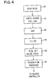
- a block diagram of the bar code reader 26 comprising a reader head block 40 which includes a light sensor mechanism for generating light beams and optical elements arranged in a conventional manner to focus the light beams at the surface of the document and for gathering the reflected light beams from the document, a photosensor and pre-amp block 42 which includes a plurality of photo-detectors (Fig.
- amplification block 46 which includes a stage of amplifiers for amplifying the output signals of the pre- amplifier block 42, a filter block 48 for filtering out unwanted noise in the signals received from the amplification block 46, a peak detector and majority selecting logic block for converting the analog signals into corresponding binary signals and a majority selection logic unit for qualifying the binary signals as a bar or not, and a recognition processor block 52 for decoding the bars detected by the read head block 40.
- FIG. 2 there is shown a schematic representation of a bar printed on a document transported through the apparatus 20 (Fig. 1) and sensed by the bar code reader 26 thereof.
- the bar indicated generally by the numeral 54 comprises a series of eight dots 56 vertically aligned to form the bar and which are printed in fluorescent ink. Aligned with the bar 54 in a sensing position are twelve photo-detectors 44 which comprise the read head block 40 (Fig. 4), and of which twelve photo-detectors eight will be positioned to sense the eight dots 56 comprising the bar 54.
- the upper two photo-detectors and the lower two photo-detectors provide detection of the bar 54 during an overscan or underscan read condition which occurs due to the misalignment of the photo-detectors 44 with the bar 54.
- the bars 54 printed on the document, such as check 58 comprise a code in which the presence or absence of a bar within a prescribed number of bar positions represents a character in a manner that is well-known in the art.
- the alignment of the bars 54 with the photo- detectors 44 when a document is in a skewed position is shown in Fig. 3. This arrangement will be discussed more fully hereinafter.
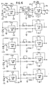
- each photo-detector 44 (Figs. 2 and 3) comprises an HP 4203 reverse bias photo-diode 60 which is commercially available from the Intel Corporation of Santa Clara, California, and which is supplied with a -12 volt power supply over line 62.
- the diode 60 will output a voltage signal between 0 and 12 volts depending on the density of the light beams reflected from the document 58. Since the dots 56 are printed in fluorescent ink, the sensing of the dots will produce a higher voltage output of the sensor 60 than the level of the signal when sensing the absence of a dot.
- the output signal of the sensor 60 is transmitted over line 64 to the negative input of a TL084 operational amplifier 66 comprising the pre-amplifier stage of the block 42 (Fig. 4).
- the amplified output analog signal of the amplifier is fed back over line 68 through a 22M resistor 70 to produce the gain for the amplifier.
- the output of the amplifier is coupled over line 72 and through a .47 pf coupling capacitor 74 to the positive input of a second TL084 operational amplifier 76 whose output signal is fed back over line 78 and through the 56K feedback resistor 80 and over line 82 to the negative input of the amplifier 76 for controlling the gain of the amplifier.
- the gain of the amplifier 76 is further controlled by a 500 ohm variable resistor 84 and a 470 ohm resistor 86.
- the input line 72 is grounded through a 100K resistor 87.
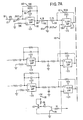
- the amplified analog voltage output signal of the amplifier 76 is outputted over line 88 to the negative input of a further TL084 operational amplifier 90 (Fig. 7A) which applies a threshold value to the analog signal for filtering out any noise signals therein.
- the amplifier 90 as well as all other TL084 operational amplifiers employed in the present invention, are commercially available from Texas Instruments Corporation of Dallas, Texas.
- the inputted signal appearing on line 88 is transmitted through a 47K voltage resistor 92 and is inverted by a .0022 pf capacitor 84.
- a 740 pf capacitor 96 is connected in a feedback configuration from the output line 98 of the amplifier 90 to the input line 88 to provide the filtering action of the amplifier.
- a 39K feedback resistor 100 is connected in a similar manner.
- the filtered output signal of the operational amplifier 90 is transmitted through a compensating network comprising a 4.7K resistor 102 and .0022 ⁇ f capacitor 104.
- the resulting signal is then transmitted through a 2.7K dropping resistor 106 to the positive input of still a further TL084 operational amplifier 108 which includes a 330K feedback resistor 110.
- Such amplifier 108 will output a square wave signal in accordance with the upper voltage limit set by the level of the voltage signal appearing at the positive input of the amplifier 108.
- the amplifier 108 also receives a negative bias over line 116 derived from a pair of transistors 112 and 114 (Fig. 7A) wired in series and connected to a +5 volt power source 118. This negative bias which appears on line 116 provides a lower limit to the square wave response of the amplifier 108.
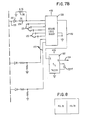
- This binary output signal of the amplifier 108 is then transmitted over line 120 through a diode 122 (Fig. 7B) which removes any remaining negative pulses contained in the signal and through a signal matching network composed of the 2K resistor 124 and a further 4.7K resistor 126.
- the resulting signal is then transmitted to one input of an Intel 82S100 logic array 128 which is also commercially available from the Intel Corporation of Santa Clara, California.
- each of the binary signals representing the output of the photodetectors 44 (Figs. 2 and 3) is transmitted over line 120 to the logic array 128.
- the logic array 128, comprising essentially a plurality of AND gates, will output a high signal over line 130 when the following two conditions are true: at least five of the eight inputted binary signals 120 received has a high signal level indicating the sensing of a dot 56 (Figs. 2 and 3) and that of the dots sensed, no more than two of the dots are separated by a blank space (in other words, when there is not more than one location in the array of sensing devices in which two sensing devices producing analog signals corresponding to binary signals having a high signal level are separated by a sensing device producing an analog signal corresponding to a binary signal having a low second signal level). It will be seen from Figs.
- the high output signal of the array 128 is transmitted over the line 130 to a set input of a 74LS74 flip-flop 132 which will output a high signal over the Q output line 134 to the recognition processor block 52 (Fig. 4) for use in decoding the sensed coded bars and to output the resulting data signal to a reader controller associated with the bar code reader 26.
Landscapes
- Physics & Mathematics (AREA)
- Engineering & Computer Science (AREA)
- Electromagnetism (AREA)
- Health & Medical Sciences (AREA)
- General Health & Medical Sciences (AREA)
- Toxicology (AREA)
- Artificial Intelligence (AREA)
- Computer Vision & Pattern Recognition (AREA)
- General Physics & Mathematics (AREA)
- Theoretical Computer Science (AREA)
- Character Input (AREA)
- Facsimile Scanning Arrangements (AREA)
Claims (7)
Applications Claiming Priority (2)
| Application Number | Priority Date | Filing Date | Title |
|---|---|---|---|
| US06/439,148 US4484068A (en) | 1982-11-04 | 1982-11-04 | Bar code processing apparatus |
| US439148 | 1982-11-04 |
Publications (2)
| Publication Number | Publication Date |
|---|---|
| EP0112014A1 EP0112014A1 (fr) | 1984-06-27 |
| EP0112014B1 true EP0112014B1 (fr) | 1987-09-16 |
Family
ID=23743485
Family Applications (1)
| Application Number | Title | Priority Date | Filing Date |
|---|---|---|---|
| EP83306692A Expired EP0112014B1 (fr) | 1982-11-04 | 1983-11-03 | Appareil pour la lecture de codes à barres |
Country Status (5)
| Country | Link |
|---|---|
| US (1) | US4484068A (fr) |
| EP (1) | EP0112014B1 (fr) |
| JP (1) | JPS5995673A (fr) |
| CA (1) | CA1196724A (fr) |
| DE (2) | DE3373735D1 (fr) |
Families Citing this family (7)
| Publication number | Priority date | Publication date | Assignee | Title |
|---|---|---|---|---|
| US4578570A (en) * | 1984-08-14 | 1986-03-25 | Ncr Canada Ltd.-Ncr Canada Ltee | Bar code processing apparatus |
| US4682015A (en) * | 1985-03-07 | 1987-07-21 | Hewlett-Packard Company | Low powered high ambient light bar code reader circuit |
| USH681H (en) | 1987-06-05 | 1989-09-05 | Dot matrix print detector | |
| US5086215A (en) * | 1988-10-26 | 1992-02-04 | National Computer Systems, Inc. | Method and apparatus for discriminating or locating bar codes for an optical mark reader |
| US5357581A (en) * | 1991-11-01 | 1994-10-18 | Eastman Kodak Company | Method and apparatus for the selective filtering of dot-matrix printed characters so as to improve optical character recognition |
| DE69228647T2 (de) * | 1991-11-01 | 1999-09-23 | Eastman Kodak Co., Rochester | Verfahren und Gerät zur Detektion von Text in Punktmatrixdruck zur Verbesserung von optischer Zeichenerkennung |
| GB0314422D0 (en) * | 2003-06-20 | 2003-07-23 | Qinetiq Ltd | Image processing system |
Family Cites Families (9)
| Publication number | Priority date | Publication date | Assignee | Title |
|---|---|---|---|---|
| NL130456C (fr) * | 1961-10-02 | |||
| US3473036A (en) * | 1966-02-16 | 1969-10-14 | North American Rockwell | Code matrix reader |
| NL143055B (nl) * | 1969-01-03 | 1974-08-15 | Nederlanden Staat | Inrichting voor het foto-elektrisch aflezen van een digitale codevoorstelling. |
| US3784795A (en) * | 1972-06-20 | 1974-01-08 | Computer Identics Corp | Label reader |
| US3900832A (en) * | 1973-09-17 | 1975-08-19 | Taplin Business Machines | Bar code processing and detecting system |
| US4162035A (en) * | 1977-09-23 | 1979-07-24 | General Signal Corporation | High resolution optical position code detector for information recorded on record carrier partially in humanly intelligible form |
| WO1982002105A1 (fr) * | 1980-12-09 | 1982-06-24 | Hudson Geoffrey M | Lecture d'informations stockees dans des unites d'information de formats multiples |
| DE3279040D1 (en) * | 1981-04-09 | 1988-10-20 | Recognition Equipment Inc | Ocr and bar code reader with optimized sensor |
| US4402088A (en) * | 1981-04-09 | 1983-08-30 | Recognition Equipment Incorporated | OCR And bar code reading using area array |
-
1982
- 1982-11-04 US US06/439,148 patent/US4484068A/en not_active Expired - Lifetime
-
1983
- 1983-10-19 CA CA000439332A patent/CA1196724A/fr not_active Expired
- 1983-10-27 JP JP58200130A patent/JPS5995673A/ja active Pending
- 1983-11-03 EP EP83306692A patent/EP0112014B1/fr not_active Expired
- 1983-11-03 DE DE8383306692T patent/DE3373735D1/de not_active Expired
- 1983-11-03 DE DE198383306692T patent/DE112014T1/de active Pending
Also Published As
| Publication number | Publication date |
|---|---|
| JPS5995673A (ja) | 1984-06-01 |
| EP0112014A1 (fr) | 1984-06-27 |
| DE3373735D1 (en) | 1987-10-22 |
| US4484068A (en) | 1984-11-20 |
| DE112014T1 (de) | 1984-12-20 |
| CA1196724A (fr) | 1985-11-12 |
Similar Documents
| Publication | Publication Date | Title |
|---|---|---|
| EP0172727B1 (fr) | Procédé et dispositif de détection d'informations codées par barres | |
| US5431288A (en) | Mail sorting apparatus | |
| US5073954A (en) | Bar code location and recognition processing system | |
| US6325420B1 (en) | Method for embedding non-intrusive encoded data in printed matter and system for reading same | |
| US5235652A (en) | Qualification system for printed images | |
| EP0036149A2 (fr) | Lecteur optique de caractères | |
| JPH0210479A (ja) | データ処理フォームおよび安全装置の形成方法 | |
| US8369601B2 (en) | Method of processing a check in an image-based check processing system and an apparatus therefor | |
| US3675201A (en) | Threshold voltage determination system | |
| WO2000079469A2 (fr) | Dispositif et procedes de balayage d'image de documents de taille et d'orientation variables | |
| EP0085749B1 (fr) | Enregistrement lisible par machine | |
| US3870865A (en) | Method and apparatus for optical reading of recorded data | |
| CA1276725C (fr) | Systeme d'affichage de lignes de programmation | |
| EP0112014B1 (fr) | Appareil pour la lecture de codes à barres | |
| US8783570B2 (en) | Reader with optical character recognition | |
| JP2002015312A (ja) | 情報取得方法、情報取得装置および文字認識装置 | |
| JPH0950475A (ja) | マーク検出方法および装置 | |
| US3900832A (en) | Bar code processing and detecting system | |
| JPH0431436B2 (fr) | ||
| JPH04111082A (ja) | バーコード読取装置 | |
| JPS61234479A (ja) | 光学式読取装置 | |
| JP2815019B2 (ja) | 文字・マークの検出装置 | |
| EP0268983A2 (fr) | Circuit de codage binaire | |
| JP2023131226A (ja) | 情報読取装置 | |
| JP2023117589A (ja) | スキャナー、スキャナーの制御方法、及び情報処理システム |
Legal Events
| Date | Code | Title | Description |
|---|---|---|---|
| PUAI | Public reference made under article 153(3) epc to a published international application that has entered the european phase |
Free format text: ORIGINAL CODE: 0009012 |
|
| AK | Designated contracting states |
Designated state(s): DE FR GB |
|
| EL | Fr: translation of claims filed | ||
| DET | De: translation of patent claims | ||
| 17P | Request for examination filed |
Effective date: 19841126 |
|
| GRAA | (expected) grant |
Free format text: ORIGINAL CODE: 0009210 |
|
| AK | Designated contracting states |
Kind code of ref document: B1 Designated state(s): DE FR GB |
|
| REF | Corresponds to: |
Ref document number: 3373735 Country of ref document: DE Date of ref document: 19871022 |
|
| ET | Fr: translation filed | ||
| PLBE | No opposition filed within time limit |
Free format text: ORIGINAL CODE: 0009261 |
|
| STAA | Information on the status of an ep patent application or granted ep patent |
Free format text: STATUS: NO OPPOSITION FILED WITHIN TIME LIMIT |
|
| 26N | No opposition filed | ||
| PGFP | Annual fee paid to national office [announced via postgrant information from national office to epo] |
Ref country code: FR Payment date: 19890929 Year of fee payment: 7 |
|
| PGFP | Annual fee paid to national office [announced via postgrant information from national office to epo] |
Ref country code: GB Payment date: 19891031 Year of fee payment: 7 |
|
| PGFP | Annual fee paid to national office [announced via postgrant information from national office to epo] |
Ref country code: DE Payment date: 19891201 Year of fee payment: 7 |
|
| PG25 | Lapsed in a contracting state [announced via postgrant information from national office to epo] |
Ref country code: GB Effective date: 19901103 |
|
| GBPC | Gb: european patent ceased through non-payment of renewal fee | ||
| PG25 | Lapsed in a contracting state [announced via postgrant information from national office to epo] |
Ref country code: FR Effective date: 19910731 |
|
| PG25 | Lapsed in a contracting state [announced via postgrant information from national office to epo] |
Ref country code: DE Effective date: 19910801 |
|
| REG | Reference to a national code |
Ref country code: FR Ref legal event code: ST |