EP0112019A1 - Raccord électrique à fiche - Google Patents
Raccord électrique à fiche Download PDFInfo
- Publication number
- EP0112019A1 EP0112019A1 EP83306740A EP83306740A EP0112019A1 EP 0112019 A1 EP0112019 A1 EP 0112019A1 EP 83306740 A EP83306740 A EP 83306740A EP 83306740 A EP83306740 A EP 83306740A EP 0112019 A1 EP0112019 A1 EP 0112019A1
- Authority
- EP
- European Patent Office
- Prior art keywords
- contact
- sections
- signal
- ground
- members
- Prior art date
- Legal status (The legal status is an assumption and is not a legal conclusion. Google has not performed a legal analysis and makes no representation as to the accuracy of the status listed.)
- Granted
Links
- 239000004020 conductor Substances 0.000 claims abstract description 36
- 239000002184 metal Substances 0.000 claims description 5
- 239000007787 solid Substances 0.000 claims 1
- 230000005540 biological transmission Effects 0.000 description 6
- 238000004891 communication Methods 0.000 description 2
- 239000003989 dielectric material Substances 0.000 description 2
- 239000000463 material Substances 0.000 description 2
- 210000001364 upper extremity Anatomy 0.000 description 2
- 238000003466 welding Methods 0.000 description 2
- 238000010276 construction Methods 0.000 description 1
- 238000002788 crimping Methods 0.000 description 1
- 238000003780 insertion Methods 0.000 description 1
- 230000037431 insertion Effects 0.000 description 1
- 238000002955 isolation Methods 0.000 description 1
- 238000000034 method Methods 0.000 description 1
- 238000000465 moulding Methods 0.000 description 1
Images




Classifications
-
- H—ELECTRICITY
- H01—ELECTRIC ELEMENTS
- H01R—ELECTRICALLY-CONDUCTIVE CONNECTIONS; STRUCTURAL ASSOCIATIONS OF A PLURALITY OF MUTUALLY-INSULATED ELECTRICAL CONNECTING ELEMENTS; COUPLING DEVICES; CURRENT COLLECTORS
- H01R24/00—Two-part coupling devices, or either of their cooperating parts, characterised by their overall structure
- H01R24/28—Coupling parts carrying pins, blades or analogous contacts and secured only to wire or cable
- H01R24/30—Coupling parts carrying pins, blades or analogous contacts and secured only to wire or cable with additional earth or shield contacts
-
- H—ELECTRICITY
- H01—ELECTRIC ELEMENTS
- H01R—ELECTRICALLY-CONDUCTIVE CONNECTIONS; STRUCTURAL ASSOCIATIONS OF A PLURALITY OF MUTUALLY-INSULATED ELECTRICAL CONNECTING ELEMENTS; COUPLING DEVICES; CURRENT COLLECTORS
- H01R12/00—Structural associations of a plurality of mutually-insulated electrical connecting elements, specially adapted for printed circuits, e.g. printed circuit boards [PCB], flat or ribbon cables, or like generally planar structures, e.g. terminal strips, terminal blocks; Coupling devices specially adapted for printed circuits, flat or ribbon cables, or like generally planar structures; Terminals specially adapted for contact with, or insertion into, printed circuits, flat or ribbon cables, or like generally planar structures
- H01R12/70—Coupling devices
- H01R12/71—Coupling devices for rigid printing circuits or like structures
- H01R12/75—Coupling devices for rigid printing circuits or like structures connecting to cables except for flat or ribbon cables
-
- H—ELECTRICITY
- H01—ELECTRIC ELEMENTS
- H01R—ELECTRICALLY-CONDUCTIVE CONNECTIONS; STRUCTURAL ASSOCIATIONS OF A PLURALITY OF MUTUALLY-INSULATED ELECTRICAL CONNECTING ELEMENTS; COUPLING DEVICES; CURRENT COLLECTORS
- H01R13/00—Details of coupling devices of the kinds covered by groups H01R12/70 or H01R24/00 - H01R33/00
- H01R13/62—Means for facilitating engagement or disengagement of coupling parts or for holding them in engagement
- H01R13/627—Snap or like fastening
-
- H—ELECTRICITY
- H01—ELECTRIC ELEMENTS
- H01R—ELECTRICALLY-CONDUCTIVE CONNECTIONS; STRUCTURAL ASSOCIATIONS OF A PLURALITY OF MUTUALLY-INSULATED ELECTRICAL CONNECTING ELEMENTS; COUPLING DEVICES; CURRENT COLLECTORS
- H01R2107/00—Four or more poles
Definitions
- This invention relates to electrical connectors and more particularly to an electrical plug connector in which electrical conductors of electrical cables are terminated to contact members and the terminations are sealingly secured in a housing that supports the cables and is latchably mounted in a polarized position in a connector-receiving member.
- Electrical connectors for transmission cables terminate the conductors of such cables.
- the connectors are generally detachably connected to other electrical connectors for transmitting electrical signals from a transmission source to a receiving member or vice versa.
- the connectors must be constructed to minimize losses or irregularities in the signals being transmitted from the transmission source to the receiving member.
- the construction of the connectors must also be concerned with electrical performance characteristics so that they are not affected by wear and handling that results when equipment is moved and detachable connection and reconnection with other connectors take place.
- an electrical plug connector of the type comprising an electrical contact assembly including a slab-like dielectric contact-carrying member on which signal and ground contact members are mounted at opposite sides, electrical cables having signal and ground conductors-electrically connected respectively to conductor-connecting sections of the signal and ground contact members, and a dielectric housing member on the electrical contact assembly, is characterized in that mid sections of the signal contact members and a planar section of the ground contact member are secured to the contact-carrying member and signal and ground contact sections extend outwardly from a front surface of the contact-carrying member; said housing member is secured onto the contact assembly and sections of the electrical cables thereby spacing, supporting and providing strain relief for the cables the signal and ground contact sections extending outwardly from the front end of the housing member.
- the housing member has polarizing latching members that latch the plug connector in a polarized position in a connector-receiving member.
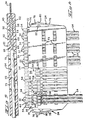
- a multilayer.- circuit board 10 has areas 12 in which matrices of electrical receptacle contacts 14 are disposed.
- Connector-receiving members 16 are secured in position on board 10 via bolts 18.
- Spaced projections 20 are located along the inside surfaces of the tops and bottoms of members 16, forming channels in which slab-like electrical plug connectors 22 are latchably secured by flexible latch members 24 engaging surfaces 26 in openings 28 of members,16 as shown in Figures 8 and 9. This enables front sections of connectors 22 to be positioned through front openings 30 in members 16 so that tab contact sections 32 and 34 of connectors 22 can be electrically connected with respective receptacle contacts 14 in areas 12.
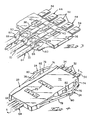
- FIGS. 2 through 9 illustrate electrical plug connector 22 in greater detail.
- a slab-like contact-carrying member 36 moulded from a suitable dielectric material has a series of three spaced recesses 38 located in one surface thereof.
- a pair of spaced circular projections 42 extends outwardly from the other surface of member 36.
- Signal contact members 44 are stamped and formed from . suitable sheet metal stock and they include contact sections 32, central sections 46 having oblong holes 48 therein, and conductor-connecting or ferrule sections 50. Each of contact sections 32 is folded back to provide a double layer of metal, the layers of which are maintained in spaced relationship with one another by an inwardly- directed projection 52 formed in one layer.
- Central section 46 is planar and is disposed in a respective recess 38 of contact-carrying member 36 with oblong projection 40 extending through oblong hole 48.
- contact sections 32 When signal contact members 44 are secured in position in recesses 38 of contact-carrying member 36 via the outer ends of oblong projections 40 being enlarged by the application of pressure or heat, contact sections 32 extend outwardly from the front end of member 36 along the longitudinal axis thereof while conductor-connecting sections 50 extend outwardly from the back end of member 36 along the same plane containing recesses 38. Sections of the contact member 44 between the contact section 32 and the central sections 46 are bent to position the contact sections 32 generally in a medial plane of the slab-like member 36.
- a ground contact member 54 has an elongated planar section 56 along which are disposed holes 58 for engagement with circular projections 42 when planar section 56 is disposed against the bottom surface of contact-carrying member 36 whereafter the outer ends of projections 42 are enlarged by the application of pressure or heat thereby securing ground contact member 54 onto member 36.
- a pair of ground contact sections 34 Adjacent the outer contact sections of the series of signal contact sections 32, a pair of ground contact sections 34 extend outwardly from ground contact member 54, at one side, generally in the same manner as contact sections 32 and they have the same double layer configuration as contact sections 32 so that ground contact sections 34 and are displaced from section 56 to lie coplanar with contact sections 32.
- Four conductor-connecting sections 60 extend outwardly from planar section 56 at the other side of the ground contact member 54 and are spaced apart to extend outwardly from the back end of member 36 in alternating spaced relationship with respect to the section 50.
- an electrical contact assembly is formed with contact sections 32 and 34 disposed generally in a medial plane at the front end of contact-carrying member 36.
- Ground contact sections 34 are disposed adjacent the outer contact sections of the series of three signal contact sections 32.
- the arrangement of signal contact sections and ground contact sections can be in any manner as desired with ground contact sections 34 on each side of one or more signal contact sections 32 to make certain that optimum isolation of the signal information being processed along signal contact sections 32 is obtained.
- Conductor-connecting sections 50 and 60 are laterally spaced with respect to one another in alternating manner as shown in Figure 3 and each conductor-connecting section 50 is centrally spaced with respect to conductor-connecting sections 60 on each side thereof as shown in Figures 3 and 6.
- Contact-carrying member 36 spaces the signal contact members 44 relative to each other and relative to ground contact member 54.
- Signal conductors 62 of three-lead coaxial cables 64 are disposed in the respective conductor-connecting sections 50 of signal contact members 44 while ground or drain conductors 66 of each of cables 64 are disposed in respective conductor-connecting sections 60 immediately below and to each side of conductor-connecting sections 50.
- Each cable 64 has a conductive coated plastic outer conductor surrounding the insulative sheath 68 covering signal conductors 62 which is electrically connected with a pair of drain conductors 66 thereby forming the three-lead coaxial cable 64 which also includes outer dielectric jacket 70.
- Signal conductors 62 and drain conductors 66 are secured in conductor-connecting sections 50 and 60 in accordance-with conventional crimping practices thereby terminating signal conductors 62 in respective conductor-connecting sections 50 of signal contact members 44 and drain conductors 66 in respective conductor-connecting sections 60 of ground contact member 54.
- the conductor-connecting sections 60 are in a modified figure eight configuration to position drain conductors 66 from adjacent cables therein.
- signal conductors 62 and drain conductors 66 can be electrically connected to conductor-connecting sections 50 and 60 respectively by the use of a laser to laser-weld the conductors to the conductor-connecting sections.
- the terminated assembly is positioned in a mould which includes cable-positioning members so that dielectric housing 72 of suitable dielectric material may be moulded onto contact-carrying member 36 including the parts of the signal and ground contacts secured thereto and the terminations of cables 64 to conductor-connecting sections 50 and 60. Openings 73 are formed in housing 72 due to the cable-positioning members. Housing 72 also covers the inner parts of contact sections 32 and 34 as shown in Figure 5, and also covers sections of cables 64 to space and support them and provide strain relief therefor. Housing 72 also environmentally seals the terminations, stabilizes the contact sections and supports them.
- the dielectric constant of the material of contact-carrying member 36 and housing 72 is suitably substantially the same as that of the cables to maintain the integrity of the signals being transmitted along the cables and the contact members.
- Flexible latch members 24 are integrally formed during the moulding of the housing 72 and each latch member includes a forward stop surface 74 which engages against an inside surface of connector-receiving member 16 as seen in Figure 9.
- Each of flexible latch members 24 includes a front leg 76 and a rear leg 78 converging outwardly to a rear facing latch surface 80. The legs are flexed inwardly when plug 22 is inserted within connector-receiving member 16 between spaced projections 20.
- latch members 24 When stop surfaces 74 of latch members 24 engage the inside front surfaces of connector-receiving member 16, latch members 24 flex outwardly with front legs 76 extending into openings 28 to enage latching surfaces 80 with surfaces 26 thereby latchably securing plug connector 22 in position in connector-receiving member 16 as shown in Figure 9.
- Arcuate projections 82 are located on housing 72 behind legs 76 and 78 to prevent latch members 24 from being overstressed when plug connectors 22 are moved into connector-receiving member 16.
- the latch member 24 at the left side is thicker than the latch member 24 on the right side and spaced projections 20 are accordingly spaced along connector-receiving- member 16 thereby defining a polarizing arrangement to polarize.the insertion of plug connectors 22 within connector-receiving member 16 to make certain that contact sections 32 and 34 are properly electrically connected with respective electrical receptacle contacts 14.
- a three-lead transmission cable can also be used wherein a signal conductor is isolated from drain conductors on each side thereof.
- the typical assembly utilizing the prevent invention is for ends of cables 64 or transmission cables to be terminated to electrical plug connectors 22 for transmitting electrical signals with high reliability and uniformity from a transmission source to a receiving member.
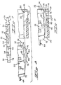
- Figures 10 through 12 illustrate an alternative embodiment of the electrical contact assembly wherein contact-carrying member 36A includes a conductor-positioning section 84 along which are channels 86 and 88.
- Channels 86 are centrally aligned with recesses 38A in which signal contact members 44A are secured via oblong projections 40A so that signal conductors 62 of cables 64 are positoned in channels 86 and in engagement with respective conductor-connecting sections 90 of signal contact members 44A which are engaged with conductor-positioning section 84.
- Ground conductors 66 of cables 64 are positioned along channels 88 on each side of a respective channel 86 and in engagement with a conductor-connecting section 92 of ground contact member 54A secured onto contact-carrying member 36A via projections 42A with section 92 engaged with section 84.
- Conductors 62 and 66 are welded respectively to conductor-connecting sections 90 of contact members 44A and conductor-connecting section 92 of contact member 54A, preferably by laser-welding techniques. Housing 92A is molded onto the terminated contact assembly.
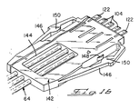
- Figures 13-16 illustrate a further embodiment of the electrical contact assembly wherein contact-carrying member 36B includes conductor-positioning section 94 along which channels 96 are located in one side and channels 98 are located in the other side. Channels 96 are in communication with recesses 100 and both of channels 96 and 98 include beveled surfaces to guide signal conductors 62 and ground conductors 66 of cables 64 respectively along channels 96 and 98.
- Signal contact members 102 are stamped and formed from pre-rolled or pre-milled metal stock with contact sections 104 being thicker than bent sections 106 which are thicker than central or mid sections 108 and ferrule sections 110.
- Mid sections 108, part of bent sections 106, and ferrule sections 110 of signal contact members 102 are disposed in respective recesses 100 with oblong projections 112 in recesses 100 extending through oblong holes 114 of mid sections 108 and ferrule sections being disposed between aligning projections 116 at the inner ends of recesses 100;-Aligning projections 116 align ferrule sections 110 in recesses 100 so that slots 118 in ferrule sections 110 are in alignment with respective channels 96, slots 118 having a width slightly less than the diameter of signal conductors 62 so that they can be force-fitted thereinto.
- Ground contact member 120 is stamped and formed from pre-rolled or pre-milled metal stock with contact sections 122 being thicker than bent sections 124 which are thicker than central section 126 which has a folded-over section 128 in which slots 130 are located. Slots 130 -are in communication with respective openings 132 in bight section 134 which neck down as they merge with slots 130. The width of slots 130 is slightly smaller than the diameter of conductors 66 so that they can be force-fitted thereinto.
- Planar section 126 has holes 136 through which circular projections 138 on contact-carrying member 36B extend when ground contact member 120 is mounted thereon. Projections 138 are mechanically or thermally deformed thereby securing contact member 120 on member 36B with contact sections 122 extending outwardly from and being centrally aligned along the front surface of member 36B so that contact sections 104 and 122 are in alignment. Planar section 126 also has openings 140 therein which are designed in size and location to tailor the impedance of the assembly to approximate the characteristic impedance of the cable.
- conductors 62 and 66 of cables 64 are guided by channels 96 and 98 so as to be positioned along slots 118 and 130 of respective contact members 102 and 120. These conductors are then force-fitted into slots l18 and 130 whereafter they are laser welded in position in accordance with conventional welding practices thereby forming the electrical contact assembly as shown in Figures 14 and 15.
- Dielectric housing 142 as shown in Figure 16 is moulded onto the contact assembly in the same manner as that of housing 72 and housing 142 has a single opening 144 to minimize engagement with cables 64 to prevent distortion thereto.
- Integral flexible latch members 146 of different widths extend outwardly from the sides of housing 142 and arcuate projections 148, 150 are located on housing 142 and latch members 146 to prevent overstressing of latch members 146.
- Housing 142 otherwise functions the same as housing 72 and the dielectric constant of the material of member 36B and housing 142 is substantially the same as that of cables 64 to maintain the integrity of the signals being transmitted along the cables and the plug member.
Landscapes
- Details Of Connecting Devices For Male And Female Coupling (AREA)
- Connector Housings Or Holding Contact Members (AREA)
- Coupling Device And Connection With Printed Circuit (AREA)
Applications Claiming Priority (4)
| Application Number | Priority Date | Filing Date | Title |
|---|---|---|---|
| US44247282A | 1982-11-17 | 1982-11-17 | |
| US442472 | 1982-11-17 | ||
| US53601783A | 1983-09-26 | 1983-09-26 | |
| US536017 | 1983-09-26 |
Publications (2)
| Publication Number | Publication Date |
|---|---|
| EP0112019A1 true EP0112019A1 (fr) | 1984-06-27 |
| EP0112019B1 EP0112019B1 (fr) | 1986-10-22 |
Family
ID=27033175
Family Applications (1)
| Application Number | Title | Priority Date | Filing Date |
|---|---|---|---|
| EP19830306740 Expired EP0112019B1 (fr) | 1982-11-17 | 1983-11-04 | Raccord électrique à fiche |
Country Status (6)
| Country | Link |
|---|---|
| EP (1) | EP0112019B1 (fr) |
| BR (1) | BR8306248A (fr) |
| CA (1) | CA1198789A (fr) |
| DE (1) | DE3367141D1 (fr) |
| IE (1) | IE54908B1 (fr) |
| MX (1) | MX159351A (fr) |
Cited By (19)
| Publication number | Priority date | Publication date | Assignee | Title |
|---|---|---|---|---|
| WO1986001946A1 (fr) * | 1984-09-20 | 1986-03-27 | Amp Incorporated | Connecteur electrique a double rangee |
| EP0211496A1 (fr) * | 1985-07-12 | 1987-02-25 | The Whitaker Corporation | Connecteur électrique à double rangée de connexions |
| US4655515A (en) * | 1985-07-12 | 1987-04-07 | Amp Incorporated | Double row electrical connector |
| WO1987002195A1 (fr) * | 1985-10-03 | 1987-04-09 | Ab Bofors | Ameliorations aux contacteurs multi-polaires |
| EP0261905A3 (en) * | 1986-09-24 | 1989-02-22 | Elco Corporation | An electrical connector and a method for connecting wires thereto |
| US4875877A (en) * | 1988-09-12 | 1989-10-24 | Amp Incorporated | Discrete cable assembly |
| EP0251556A3 (fr) * | 1986-07-03 | 1990-01-03 | Amp Incorporated | Contact électrique à deux fentes |
| EP0426348A1 (fr) * | 1989-11-01 | 1991-05-08 | The Whitaker Corporation | Connecteur de câble avec un bas chemin d'inductance |
| EP0392689A3 (fr) * | 1989-04-13 | 1991-09-11 | The Whitaker Corporation | Connecteur à haute densité de contacts pour un support de circuits intégrés |
| EP0741921A1 (fr) * | 1994-01-25 | 1996-11-13 | The Whitaker Corporation | Connecteur electrique, boitier et contact |
| FR2741751A1 (fr) * | 1995-11-27 | 1997-05-30 | Cinch Connecteurs Sa | Connecteur electrique |
| US7901216B2 (en) | 2005-09-26 | 2011-03-08 | Apple Inc. | Magnetic connector for electronic device |
| EP2290756A3 (fr) * | 2005-09-26 | 2011-04-27 | Apple Inc. | Connecteur électromagnétique pour dispositif électronique |
| US8535088B2 (en) | 2009-10-20 | 2013-09-17 | Apple Inc. | Magnetic connector having a unitary housing |
| US8770857B2 (en) | 2008-09-30 | 2014-07-08 | Apple Inc. | Magnetic connector with optical signal path |
| US8888500B2 (en) | 2011-06-30 | 2014-11-18 | Apple Inc. | Robust magnetic connector |
| US9065205B2 (en) | 2011-08-11 | 2015-06-23 | Apple Inc. | Connector insert having a cable crimp portion with protrusions and a receptacle having label in the front |
| US9791634B2 (en) | 2008-09-30 | 2017-10-17 | Apple Inc. | Magnetic connector with optical signal path |
| US11424573B2 (en) | 2020-09-24 | 2022-08-23 | Apple Inc. | Magnetic connectors with self-centering floating contacts |
Families Citing this family (1)
| Publication number | Priority date | Publication date | Assignee | Title |
|---|---|---|---|---|
| USD348250S (en) | 1992-03-31 | 1994-06-28 | Motorola, Inc. | Set of connectors for powering an electronic device |
Citations (4)
| Publication number | Priority date | Publication date | Assignee | Title |
|---|---|---|---|---|
| US3411130A (en) * | 1967-03-13 | 1968-11-12 | Amp Inc | Electrical connector |
| DE1945862A1 (de) * | 1968-09-13 | 1970-05-14 | Int Standard Electric Corp | Riegelvorrichtung |
| US3740698A (en) * | 1971-05-12 | 1973-06-19 | Honeywell Inf Systems | Ribbon cable connector system having stress relieving means |
| GB2018054A (en) * | 1978-03-31 | 1979-10-10 | Cit Alcatel | A connector for an electric cable |
-
1983
- 1983-10-27 CA CA000439875A patent/CA1198789A/fr not_active Expired
- 1983-11-04 EP EP19830306740 patent/EP0112019B1/fr not_active Expired
- 1983-11-04 DE DE8383306740T patent/DE3367141D1/de not_active Expired
- 1983-11-14 BR BR8306248A patent/BR8306248A/pt not_active IP Right Cessation
- 1983-11-15 IE IE266383A patent/IE54908B1/en not_active IP Right Cessation
- 1983-11-16 MX MX19944383A patent/MX159351A/es unknown
Patent Citations (4)
| Publication number | Priority date | Publication date | Assignee | Title |
|---|---|---|---|---|
| US3411130A (en) * | 1967-03-13 | 1968-11-12 | Amp Inc | Electrical connector |
| DE1945862A1 (de) * | 1968-09-13 | 1970-05-14 | Int Standard Electric Corp | Riegelvorrichtung |
| US3740698A (en) * | 1971-05-12 | 1973-06-19 | Honeywell Inf Systems | Ribbon cable connector system having stress relieving means |
| GB2018054A (en) * | 1978-03-31 | 1979-10-10 | Cit Alcatel | A connector for an electric cable |
Cited By (39)
| Publication number | Priority date | Publication date | Assignee | Title |
|---|---|---|---|---|
| WO1986001946A1 (fr) * | 1984-09-20 | 1986-03-27 | Amp Incorporated | Connecteur electrique a double rangee |
| US4602830A (en) * | 1984-09-20 | 1986-07-29 | Amp Incorporated | Double row electrical connector |
| EP0211496A1 (fr) * | 1985-07-12 | 1987-02-25 | The Whitaker Corporation | Connecteur électrique à double rangée de connexions |
| US4655515A (en) * | 1985-07-12 | 1987-04-07 | Amp Incorporated | Double row electrical connector |
| WO1987002195A1 (fr) * | 1985-10-03 | 1987-04-09 | Ab Bofors | Ameliorations aux contacteurs multi-polaires |
| US4807088A (en) * | 1985-10-03 | 1989-02-21 | Aktiebolaget Bofors | Multi-polar contactors |
| EP0251556A3 (fr) * | 1986-07-03 | 1990-01-03 | Amp Incorporated | Contact électrique à deux fentes |
| EP0261905A3 (en) * | 1986-09-24 | 1989-02-22 | Elco Corporation | An electrical connector and a method for connecting wires thereto |
| US4875877A (en) * | 1988-09-12 | 1989-10-24 | Amp Incorporated | Discrete cable assembly |
| WO1990003051A1 (fr) * | 1988-09-12 | 1990-03-22 | Amp Incorporated | Connecteur de cables discret |
| EP0392689A3 (fr) * | 1989-04-13 | 1991-09-11 | The Whitaker Corporation | Connecteur à haute densité de contacts pour un support de circuits intégrés |
| EP0426348A1 (fr) * | 1989-11-01 | 1991-05-08 | The Whitaker Corporation | Connecteur de câble avec un bas chemin d'inductance |
| EP0741921A1 (fr) * | 1994-01-25 | 1996-11-13 | The Whitaker Corporation | Connecteur electrique, boitier et contact |
| EP0848455A3 (fr) * | 1994-01-25 | 1999-02-10 | The Whitaker Corporation | Connecteur électrique |
| US5888096A (en) * | 1994-01-25 | 1999-03-30 | The Whitaker Corporation | Electrical connector, housing and contact |
| FR2741751A1 (fr) * | 1995-11-27 | 1997-05-30 | Cinch Connecteurs Sa | Connecteur electrique |
| US8087939B2 (en) | 2005-09-26 | 2012-01-03 | Apple Inc. | Magnetic connector for electronic device |
| US9112304B2 (en) | 2005-09-26 | 2015-08-18 | Apple Inc. | Magnetic connector for electronic device |
| US7901216B2 (en) | 2005-09-26 | 2011-03-08 | Apple Inc. | Magnetic connector for electronic device |
| US8177560B2 (en) | 2005-09-26 | 2012-05-15 | Apple Inc. | Magnetic connector for electronic device |
| US8497753B2 (en) | 2005-09-26 | 2013-07-30 | Apple Inc. | Electromagnetic connector for electronic device |
| US11233356B2 (en) | 2005-09-26 | 2022-01-25 | Apple Inc. | Magnetic connector for electronic device |
| US8690582B2 (en) | 2005-09-26 | 2014-04-08 | Apple Inc. | Magnetic connector for electronic device |
| US10490933B2 (en) | 2005-09-26 | 2019-11-26 | Apple Inc. | Magnetic connector for electronic device |
| US10090618B2 (en) | 2005-09-26 | 2018-10-02 | Apple Inc. | Magnetic connector for electronic device |
| US8970332B2 (en) | 2005-09-26 | 2015-03-03 | Apple Inc. | Electromagnetic connector for electronic device |
| US9711893B2 (en) | 2005-09-26 | 2017-07-18 | Apple Inc. | Magnetic connector for electronic device |
| EP2290756A3 (fr) * | 2005-09-26 | 2011-04-27 | Apple Inc. | Connecteur électromagnétique pour dispositif électronique |
| US9634428B2 (en) | 2005-09-26 | 2017-04-25 | Apple Inc. | Electromagnetic connector for electronic device |
| US9791634B2 (en) | 2008-09-30 | 2017-10-17 | Apple Inc. | Magnetic connector with optical signal path |
| US8770857B2 (en) | 2008-09-30 | 2014-07-08 | Apple Inc. | Magnetic connector with optical signal path |
| US9923301B2 (en) | 2009-10-20 | 2018-03-20 | Apple Inc. | Magnetic connector having a unitary housing |
| US8535088B2 (en) | 2009-10-20 | 2013-09-17 | Apple Inc. | Magnetic connector having a unitary housing |
| US9461403B2 (en) | 2011-06-30 | 2016-10-04 | Apple Inc. | Robust magnetic connector |
| US9923290B2 (en) | 2011-06-30 | 2018-03-20 | Apple Inc. | Robust magnetic connector |
| US8888500B2 (en) | 2011-06-30 | 2014-11-18 | Apple Inc. | Robust magnetic connector |
| US9660376B2 (en) | 2011-08-11 | 2017-05-23 | Apple Inc. | Connector insert having a cable crimp portion with protrusions and a receptacle having a label in the front |
| US9065205B2 (en) | 2011-08-11 | 2015-06-23 | Apple Inc. | Connector insert having a cable crimp portion with protrusions and a receptacle having label in the front |
| US11424573B2 (en) | 2020-09-24 | 2022-08-23 | Apple Inc. | Magnetic connectors with self-centering floating contacts |
Also Published As
| Publication number | Publication date |
|---|---|
| IE54908B1 (en) | 1990-03-14 |
| IE832663L (en) | 1984-05-17 |
| BR8306248A (pt) | 1984-06-19 |
| CA1198789A (fr) | 1985-12-31 |
| MX159351A (es) | 1989-05-17 |
| EP0112019B1 (fr) | 1986-10-22 |
| DE3367141D1 (en) | 1986-11-27 |
Similar Documents
| Publication | Publication Date | Title |
|---|---|---|
| US4826443A (en) | Contact subassembly for an electrical connector and method of making same | |
| US4602831A (en) | Electrical connector and method of making same | |
| US4682840A (en) | Electrical connection and method of making same | |
| EP0112019B1 (fr) | Raccord électrique à fiche | |
| US6955565B2 (en) | Cable connector with shielded termination area | |
| US5785557A (en) | Electrical connector with protection for electrical contacts | |
| US4579404A (en) | Conductor-terminated card edge connector | |
| EP1003250B1 (fr) | Un connecteur blindé, un jeu de connecteurs blindés et procédé pour connecter un connecteur blindé avec un câble blindé | |
| EP0118168B2 (fr) | Connecteur électrique enfichable et prise assortie | |
| US5855493A (en) | Electrical connector strain relief with shield ground for multiple cables | |
| US5380223A (en) | High density electrical connector | |
| US4655515A (en) | Double row electrical connector | |
| EP0653811B1 (fr) | Connecteur électrique avec décharge de traction | |
| US7878850B2 (en) | Cable connector assembly with grounding device | |
| US7410366B2 (en) | Electrical connector assembly with reduced crosstalk and electromaganectic interference | |
| US4941849A (en) | Shielded electrical connector having an insulating cover on the shielding member | |
| US4737117A (en) | Double-row electrical connector and method of making same | |
| US6910914B1 (en) | Shielded cable end connector assembly | |
| US6210230B1 (en) | Cable connector | |
| US7892028B2 (en) | Cable connector assembly | |
| EP0653815B1 (fr) | Connecteur électrique avec borne de terre pour écran de câble | |
| JPH07201379A (ja) | パッチコネクタ | |
| US6544050B1 (en) | Electrical cable connector assembly | |
| US7267578B2 (en) | Electrical connector assembly having improved locking mechanism | |
| CN110808493B (zh) | 电连接器 |
Legal Events
| Date | Code | Title | Description |
|---|---|---|---|
| PUAI | Public reference made under article 153(3) epc to a published international application that has entered the european phase |
Free format text: ORIGINAL CODE: 0009012 |
|
| AK | Designated contracting states |
Designated state(s): BE DE FR GB IT NL SE |
|
| 17P | Request for examination filed |
Effective date: 19841211 |
|
| ITF | It: translation for a ep patent filed | ||
| GRAA | (expected) grant |
Free format text: ORIGINAL CODE: 0009210 |
|
| AK | Designated contracting states |
Kind code of ref document: B1 Designated state(s): BE DE FR GB IT NL SE |
|
| REF | Corresponds to: |
Ref document number: 3367141 Country of ref document: DE Date of ref document: 19861127 |
|
| ET | Fr: translation filed | ||
| PLBE | No opposition filed within time limit |
Free format text: ORIGINAL CODE: 0009261 |
|
| STAA | Information on the status of an ep patent application or granted ep patent |
Free format text: STATUS: NO OPPOSITION FILED WITHIN TIME LIMIT |
|
| 26N | No opposition filed | ||
| ITTA | It: last paid annual fee | ||
| REG | Reference to a national code |
Ref country code: GB Ref legal event code: 732E |
|
| EAL | Se: european patent in force in sweden |
Ref document number: 83306740.8 |
|
| PGFP | Annual fee paid to national office [announced via postgrant information from national office to epo] |
Ref country code: BE Payment date: 19951208 Year of fee payment: 13 |
|
| PG25 | Lapsed in a contracting state [announced via postgrant information from national office to epo] |
Ref country code: BE Effective date: 19961130 |
|
| BERE | Be: lapsed |
Owner name: AMP INC. (PA) (UNE SOC. DE PENNSYLVANIE) Effective date: 19961130 |
|
| PGFP | Annual fee paid to national office [announced via postgrant information from national office to epo] |
Ref country code: NL Payment date: 19980914 Year of fee payment: 16 |
|
| PGFP | Annual fee paid to national office [announced via postgrant information from national office to epo] |
Ref country code: SE Payment date: 19981105 Year of fee payment: 16 |
|
| PG25 | Lapsed in a contracting state [announced via postgrant information from national office to epo] |
Ref country code: SE Free format text: LAPSE BECAUSE OF NON-PAYMENT OF DUE FEES Effective date: 19991105 |
|
| PG25 | Lapsed in a contracting state [announced via postgrant information from national office to epo] |
Ref country code: NL Free format text: LAPSE BECAUSE OF NON-PAYMENT OF DUE FEES Effective date: 20000601 |
|
| EUG | Se: european patent has lapsed |
Ref document number: 83306740.8 |
|
| NLV4 | Nl: lapsed or anulled due to non-payment of the annual fee |
Effective date: 20000601 |
|
| REG | Reference to a national code |
Ref country code: GB Ref legal event code: IF02 |
|
| PGFP | Annual fee paid to national office [announced via postgrant information from national office to epo] |
Ref country code: GB Payment date: 20021002 Year of fee payment: 20 |
|
| PGFP | Annual fee paid to national office [announced via postgrant information from national office to epo] |
Ref country code: FR Payment date: 20021105 Year of fee payment: 20 |
|
| PGFP | Annual fee paid to national office [announced via postgrant information from national office to epo] |
Ref country code: DE Payment date: 20021127 Year of fee payment: 20 |
|
| PG25 | Lapsed in a contracting state [announced via postgrant information from national office to epo] |
Ref country code: GB Free format text: LAPSE BECAUSE OF EXPIRATION OF PROTECTION Effective date: 20031103 |
|
| REG | Reference to a national code |
Ref country code: GB Ref legal event code: PE20 |