EP0112189A2 - Verfahren und Gerät zur Kopplung eines seismischen Detektors an die Bohrlochwand - Google Patents
Verfahren und Gerät zur Kopplung eines seismischen Detektors an die Bohrlochwand Download PDFInfo
- Publication number
- EP0112189A2 EP0112189A2 EP83401433A EP83401433A EP0112189A2 EP 0112189 A2 EP0112189 A2 EP 0112189A2 EP 83401433 A EP83401433 A EP 83401433A EP 83401433 A EP83401433 A EP 83401433A EP 0112189 A2 EP0112189 A2 EP 0112189A2
- Authority
- EP
- European Patent Office
- Prior art keywords
- skate
- probe
- force
- borehole
- shoe
- Prior art date
- Legal status (The legal status is an assumption and is not a legal conclusion. Google has not performed a legal analysis and makes no representation as to the accuracy of the status listed.)
- Granted
Links
Images


Classifications
-
- G—PHYSICS
- G01—MEASURING; TESTING
- G01V—GEOPHYSICS; GRAVITATIONAL MEASUREMENTS; DETECTING MASSES OR OBJECTS; TAGS
- G01V1/00—Seismology; Seismic or acoustic prospecting or detecting
- G01V1/16—Receiving elements for seismic signals; Arrangements or adaptations of receiving elements
-
- E—FIXED CONSTRUCTIONS
- E21—EARTH OR ROCK DRILLING; MINING
- E21B—EARTH OR ROCK DRILLING; OBTAINING OIL, GAS, WATER, SOLUBLE OR MELTABLE MATERIALS OR A SLURRY OF MINERALS FROM WELLS
- E21B23/00—Apparatus for displacing, setting, locking, releasing or removing tools, packers or the like in boreholes or wells
- E21B23/01—Apparatus for displacing, setting, locking, releasing or removing tools, packers or the like in boreholes or wells for anchoring the tools or the like
-
- E—FIXED CONSTRUCTIONS
- E21—EARTH OR ROCK DRILLING; MINING
- E21B—EARTH OR ROCK DRILLING; OBTAINING OIL, GAS, WATER, SOLUBLE OR MELTABLE MATERIALS OR A SLURRY OF MINERALS FROM WELLS
- E21B47/00—Survey of boreholes or wells
-
- G—PHYSICS
- G01—MEASURING; TESTING
- G01V—GEOPHYSICS; GRAVITATIONAL MEASUREMENTS; DETECTING MASSES OR OBJECTS; TAGS
- G01V11/00—Prospecting or detecting by methods combining techniques covered by two or more of main groups G01V1/00 - G01V9/00
- G01V11/002—Details, e.g. power supply systems for logging instruments, transmitting or recording data, specially adapted for well logging, also if the prospecting method is irrelevant
- G01V11/005—Devices for positioning logging sondes with respect to the borehole wall
Definitions
- Means are provided for immobilizing in rotation the sleeve 65 when the axial position of the latter is within a determined range, so that the rotation of the shaft 38 and therefore of the sleeve 61 causes a translation of the sleeve 65.
- the sleeve 65 comprises on the drive side a part 70 of external diameter smaller than the part which carries the pins 67.
- a friction ring 71 linked in rotation with the sleeve 65 but movable axially relative to the latter.
- the ring 71 has internally an axial groove 72 in which is engaged a key 73 fixed on the sleeve 65.
- the sleeve 65 has at its end opposite the reduction gear a toothed plate 85 capable of meshing with a toothed plate 86 formed on a counter ring 87.
- the toothed plates 85 and 86 are made up of radial teeth of triangular section.
- the screw-nut system 40, 41 does not present any particular feature requiring a detailed description.
- the nut 41 is, conventionally, subject to moving only in translation, so that a rotation of the ball screw 40 in one direction causes a translation of the nut 41 in the corresponding direction.
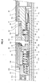
- a leaf spring 43a forming part of the aforementioned return device 43 is fixed to the probe body 29 in the vicinity of the pivot 110 of the upper arm 32 and that it passes between the brackets 111, 112 of the arm 31.
- the rod 34 passes through, on either side of the zone of engagement with the arm 31, housings 125, 126 inside which are mounted the 45 seals mentioned above.
- the oil put under pressure from the drilling mud by the compensation device 47 can circulate to the end of the rod 34 through a central passage 127.
- FIG. 6 also shows conductors 130 carried by the arm 32, which connect the pad 30 to the cartridge 22, and in FIG. 7 sheaths 131 receiving the electrical conductors which connect the cartridge 22 to the detection section and to the anchoring section, especially for ordering. motor 35.
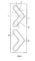
- FIG. 8 specifies the arrangement of the return device 43.
- a second spring 43b, formed of a single blade and therefore lighter than the spring 43a, is fixed by one end 135 to another core piece 136 of the arm 31, placed closer to the pivot 113 than the part 134.
- the other end 137 of the spring 43b acts on the upper arm 32 in the vicinity of its end, there again with a sliding when the arms pivot.
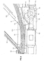
- FIG. 8 shows in more detail the anchoring pad 30.
- the pad 30, as we have seen, is mounted at the end of the upper arm 32 and of the lower arm 31, of which only one of the flanges is shown in the sectional view of Figure 8, which flanges surround the pad.
- the shoe 30 comprises a hollow body 140 on the inside and a wear plate 141 intended for contact with the wall, fixed on the shoe body 140.
- the wear plate 141 is provided on its surface with grooves in order to optimize anchoring in the wall.
- the skate body 140 is connected to the end of the upper arm 32 by a pivot 142. On the other hand, it comprises, substantially in its middle, openings 143 formed in its side walls.
- the openings 143 have the shape of rectangles rounded at the vertices, and receive a pivot 144 linked to the flanges of the lower arm 31.
- the skate body 140 is pivotally mounted relative to the upper arm 32 and it is connected to the lower arm 31 by means of the force sensor 150 which, on the one hand, is movable in translation relative to the body of skate, and on the other hand, is linked to the arm 31 by the pivot 144, the clearance between the pivot 144 and the skate body being limited by the edges of the openings 143 formed in the skate body.
- the shoe has the possibility of tilting slightly, in one direction or the other, relative to the median position, parallel to the axis of the probe, which is that shown in FIG. 8.
- the upper arm 32 pivots slightly relative to the probe, deviating from its position parallel to the lower arm 31.
- the flexing element has a lower end 165 similar to a ball joint engaged in the bottom of the housing formed inside the sheath 151.
- the strain gauges 153 are placed on inclined flats 166 formed on opposite sides of the flexing member. On each flat are two gauges, and the four gauges are connected in a "full bridge" arrangement, conventionally in the technique of measurements by strain gauges.
- the flexing element comprises conduits such as 167 for the passage of electrical conductors 168 connecting the circuit of the gauges to four connectors 169 (two for the power supply and two for transmitting the detection signal) which pass through a sealing block 170 fixed to the sheath 151. Conductors, not shown in FIG. 8, and carried by the arm 32, connect these connectors to the electronic cartridge 22.
- the shoe also carries a device 180 intended to emit an electric current to evaluate the resistivity of the surface area of the formation traversed by the drilling.
- This device shown in more detail in FIG. 10, comprises an electrode 181 made of conductive material placed on an insulator 182 itself housed in a recess of a support 183 made of conductive material acting as a mass.
- This support comprises a conduit for the passage of an electrical conductor 184 connected to the electrode 181.
- the reception of the electric current thus emitted can be ensured by the connection head 23 connecting the cartridge 22 to the cable .13.
- We can thus carry out a logging microresistivity that can be correlated with other logs made in the same borehole to determine with precision the depth of the anchoring levels.
- the probe is lowered into the borehole with the arms 31, 32 in the folded position.
- the motor 35 is not powered and is locked by its brake 37.
- the coupling device is engaged, that is to say that the toothed plates 85, 86 are engaged and the socket 88 is in abutment against the part 107.
- the resistant torque supplied by the motor opposes the opening of the arms under the action of the leaf spring 43.
- Chaucn of the rollers 66 occupies an advanced position F in the section 68a of its groove cam, in contact with the lower wall Ldu said section.
- the following phase is the actual seismic acquisition phase at the level considered.
- Several successive shots are taken by means of the source 11, and the seismic waves which have propagated in the formations are detected by the detection section.
- the detection signals produced following the respective shots are transmitted by the cartridge 24 and the cable 13 to the surface equipment 16, where they are recorded on a graphic medium and on a magnetic tape.
- the next phase is the displacement of the probe from level H 1 to a second measurement level H 2. ,
- the motor 35 remains stopped, the coupling device retains the disengaged position, the rollers 66 remaining in position D, and the shoe slides on the wall of the borehole, the contact being maintained in contact with the wall by the springs 43.
- the probe When the probe has reached the second measurement level E 2 , the anchoring, seismic acquisition, and de-anchoring operations are repeated, then the probe is raised to a third measurement level H3, etc.
- the arms 31, 32 must be closed in order to raise the probe to the surface.
- the motor 35 is started in the direct direction.
- the sleeve 65 is initially blocked in rotation by the friction ring 71, and the rollers 66 in the position D corresponding to the disengagement.
- the sleeve 65 moves until contact between the toothed plates 85, 86, then the springs 43 exerting a resistant torque on the sleeve 88, the sleeve 65. continues its movement in translation by pushing the sleeve 88 against the action of the spring 52.
- the engine torque is transmitted to the socket 88 and overcomes the resistant torque offered by the springs 43 to pivot the arms 31, 32 to their closed position along of the probe body.
Landscapes
- Life Sciences & Earth Sciences (AREA)
- Physics & Mathematics (AREA)
- Engineering & Computer Science (AREA)
- Geology (AREA)
- Mining & Mineral Resources (AREA)
- General Life Sciences & Earth Sciences (AREA)
- Environmental & Geological Engineering (AREA)
- Geophysics (AREA)
- Geochemistry & Mineralogy (AREA)
- General Physics & Mathematics (AREA)
- Fluid Mechanics (AREA)
- Acoustics & Sound (AREA)
- Remote Sensing (AREA)
- Geophysics And Detection Of Objects (AREA)
- Measurement Of Mechanical Vibrations Or Ultrasonic Waves (AREA)
Priority Applications (1)
| Application Number | Priority Date | Filing Date | Title |
|---|---|---|---|
| AT83401433T ATE30273T1 (de) | 1982-07-13 | 1983-07-12 | Verfahren und geraet zur kopplung eines seismischen detektors an die bohrlochwand. |
Applications Claiming Priority (2)
| Application Number | Priority Date | Filing Date | Title |
|---|---|---|---|
| FR8212252A FR2530345B1 (fr) | 1982-07-13 | 1982-07-13 | Procede pour coupler un detecteur sismique a la paroi d'un forage, et sonde d'acquisition sismique pour la mise en oeuvre de ce procede |
| FR8212252 | 1982-07-13 |
Publications (3)
| Publication Number | Publication Date |
|---|---|
| EP0112189A2 true EP0112189A2 (de) | 1984-06-27 |
| EP0112189A3 EP0112189A3 (en) | 1984-12-12 |
| EP0112189B1 EP0112189B1 (de) | 1987-10-14 |
Family
ID=9275940
Family Applications (1)
| Application Number | Title | Priority Date | Filing Date |
|---|---|---|---|
| EP83401433A Expired EP0112189B1 (de) | 1982-07-13 | 1983-07-12 | Verfahren und Gerät zur Kopplung eines seismischen Detektors an die Bohrlochwand |
Country Status (7)
| Country | Link |
|---|---|
| US (1) | US4575831A (de) |
| EP (1) | EP0112189B1 (de) |
| JP (1) | JPS5924281A (de) |
| AT (1) | ATE30273T1 (de) |
| CA (1) | CA1200003A (de) |
| DE (1) | DE3374086D1 (de) |
| FR (1) | FR2530345B1 (de) |
Families Citing this family (26)
| Publication number | Priority date | Publication date | Assignee | Title |
|---|---|---|---|---|
| FR2554600B1 (fr) * | 1983-11-09 | 1986-02-07 | Elf Aquitaine | Dispositif de mesure pour profil sismique dans un puits de forage |
| US4715469A (en) * | 1985-08-29 | 1987-12-29 | Petrophysical Services, Inc. | Borehole seismic receiver |
| US4784238A (en) * | 1986-07-14 | 1988-11-15 | Western Atlas International, Inc. | Large diameter borehole apparatus |
| JPH0433392Y2 (de) * | 1986-09-11 | 1992-08-11 | ||
| US4819760A (en) * | 1988-05-03 | 1989-04-11 | Atlantic Richfield Company | Locking arm for well tool |
| US4926937A (en) * | 1989-06-08 | 1990-05-22 | Western Atlas International, Inc. | Compound linkage-arm assembly for use in bore-hole tools |
| US4979585A (en) * | 1989-10-02 | 1990-12-25 | Halliburton Logging Services, Inc. | Compound suspension linkage |
| AU7347398A (en) | 1998-05-29 | 1999-12-20 | Nakajima, Hiroshi | Borehole logging tool with anchoring mechanism |
| WO2000003270A1 (en) | 1998-07-10 | 2000-01-20 | Schlumberger Limited | Borehole seismic tool |
| US6588542B2 (en) | 2000-03-14 | 2003-07-08 | Schlumberger Technology Corporation | Borehole tool actuating mechanism |
| US20020179364A1 (en) * | 2001-01-19 | 2002-12-05 | Baker Hughes Incorporated | Apparatus and methods for using a surface oscillator as a downhole seismic source |
| US6541975B2 (en) * | 2001-08-23 | 2003-04-01 | Kjt Enterprises, Inc. | Integrated borehole system for reservoir detection and monitoring |
| US7915532B2 (en) * | 2007-06-08 | 2011-03-29 | Westerngeco L.L.C. | Enhanced electrical seismic land cable |
| US7860362B2 (en) * | 2007-06-08 | 2010-12-28 | Westerngeco L.L.C. | Enhanced fiber optic seismic land cable |
| US7912333B2 (en) * | 2008-02-05 | 2011-03-22 | Schlumberger Technology Corporation | Dual conductor fiber optic cable |
| US20090251993A1 (en) * | 2008-04-04 | 2009-10-08 | Pile Dynamics, Inc. | Shear wave transducer and method of using the same |
| US7922153B2 (en) * | 2008-09-16 | 2011-04-12 | Runva Mechanical & Electrical Co, LLC | Variable speed winch |
| EP2769386A4 (de) | 2011-10-17 | 2016-02-17 | Services Petroliers Schlumberger | Doppelfunktionskabel mit faseroptischem gehäuse zur verwendung bei bohrlochoperationen |
| WO2014004026A1 (en) | 2012-06-28 | 2014-01-03 | Schlumberger Canada Limited | High power opto-electrical cable with multiple power and telemetry paths |
| US9435191B2 (en) | 2013-06-27 | 2016-09-06 | Schlumberger Technology Corporation | Downhole sensor flap and method of using same |
| JP6390025B2 (ja) * | 2014-05-21 | 2018-09-19 | 株式会社エスジオップ | 高周波振動検出装置 |
| US10781650B2 (en) | 2014-08-01 | 2020-09-22 | Halliburton Energy Services, Inc. | Downhole tool with multi-stage anchoring |
| US11725468B2 (en) | 2015-01-26 | 2023-08-15 | Schlumberger Technology Corporation | Electrically conductive fiber optic slickline for coiled tubing operations |
| US10049789B2 (en) | 2016-06-09 | 2018-08-14 | Schlumberger Technology Corporation | Compression and stretch resistant components and cables for oilfield applications |
| WO2019086572A1 (en) * | 2017-11-02 | 2019-05-09 | Sondex Wireline Limited | Sensor deployment system and method |
| RU2748175C1 (ru) * | 2020-10-09 | 2021-05-20 | федеральное государственное автономное образовательное учреждение высшего образования "Российский университет дружбы народов" (РУДН) | Скважинный сейсмический прибор |
Family Cites Families (11)
| Publication number | Priority date | Publication date | Assignee | Title |
|---|---|---|---|---|
| US2876413A (en) * | 1954-03-30 | 1959-03-03 | Schlumberger Well Surv Corp | Borehole apparatus |
| US2846662A (en) * | 1955-10-17 | 1958-08-05 | Pan American Petroleum Corp | Receiving seismic waves directionally |
| US3028542A (en) * | 1959-09-03 | 1962-04-03 | Jersey Prod Res Co | Well logging apparatus |
| FR1306134A (fr) * | 1961-08-31 | 1962-10-13 | Schlumberger Prospection | Perfectionnements aux sondes à patins employées en géophysique |
| US3356146A (en) * | 1965-06-23 | 1967-12-05 | Schlumberger Technology Corp | Well logging tool |
| US3426865A (en) * | 1966-07-22 | 1969-02-11 | Schlumberger Prospection | Borehole surveying apparatus with complementary rotation of paired transducers |
| US3566682A (en) * | 1969-01-22 | 1971-03-02 | Schlumberger Technology Corp | Radioactivity and electrical logging tool combination |
| FR2138335B1 (de) * | 1971-05-24 | 1974-03-08 | Schlumberger Prospection | |
| JPS5225408A (en) * | 1975-08-20 | 1977-02-25 | Japan Petroleum Exploration Co | Bed crack detecting method using vertical and horizontal wave |
| US4120353A (en) * | 1977-04-19 | 1978-10-17 | Dresser Industries, Inc. | Device to move density logging tool against well wall |
| US4117394A (en) * | 1977-06-10 | 1978-09-26 | Schlumberger Technology Corporation | Well logging apparatus with pad-mounted vertical electrode array for measuring the resistivity of the flushed zone |
-
1982
- 1982-07-13 FR FR8212252A patent/FR2530345B1/fr not_active Expired
-
1983
- 1983-07-08 US US06/511,814 patent/US4575831A/en not_active Expired - Fee Related
- 1983-07-12 EP EP83401433A patent/EP0112189B1/de not_active Expired
- 1983-07-12 CA CA000432295A patent/CA1200003A/en not_active Expired
- 1983-07-12 DE DE8383401433T patent/DE3374086D1/de not_active Expired
- 1983-07-12 AT AT83401433T patent/ATE30273T1/de active
- 1983-07-13 JP JP58126296A patent/JPS5924281A/ja active Pending
Also Published As
| Publication number | Publication date |
|---|---|
| FR2530345A1 (fr) | 1984-01-20 |
| CA1200003A (en) | 1986-01-28 |
| ATE30273T1 (de) | 1987-10-15 |
| US4575831A (en) | 1986-03-11 |
| FR2530345B1 (fr) | 1985-06-21 |
| JPS5924281A (ja) | 1984-02-07 |
| DE3374086D1 (en) | 1987-11-19 |
| EP0112189B1 (de) | 1987-10-14 |
| EP0112189A3 (en) | 1984-12-12 |
Similar Documents
| Publication | Publication Date | Title |
|---|---|---|
| EP0100708B1 (de) | Verfahren und Gerät zur Sammlung von seismischen Signalen in einem Bohrloch | |
| EP0112189B1 (de) | Verfahren und Gerät zur Kopplung eines seismischen Detektors an die Bohrlochwand | |
| EP0330558B1 (de) | Verfahren und Vorrichtung zum Übertragen von Information per Kabel und per Spülungsdruckwellen | |
| EP0388315B1 (de) | Verfahren und Vorrichtung zum Aufzeichnen von Bohrlochmessungen mit einem Sensor, der die Bohrlochwand entlang des Umfangs abtastet, insbesondere um diesen Sensor zu kalibrieren | |
| CA1107494A (fr) | Sonde a patin rotatif pour effectuer des mesures dans un forage | |
| EP0558379B1 (de) | System und Verfahren zur physikalischer Daten-Sammlung während des Bohrens | |
| FR2619453A1 (fr) | Procede pour coupler un module de detection sismique a la paroi d'un sondage et sonde pour sa mise en oeuvre | |
| FR2697578A1 (fr) | Centreur pour sondage. | |
| FR2512488A1 (fr) | Procede et dispositif de diagraphie utilisant une sonde equipee de patins de mesure | |
| EP0122839A1 (de) | Verfahren und Vorrichtung zum Messen und/oder Ausführen von Arbeiten in einem Bohrloch | |
| EP0773344B1 (de) | Vorrichtung zur Erkundung einer horizontal durchbohrten Gesteinsformation mit mehreren verankerbaren Messsonden | |
| FR2710987A1 (fr) | Dispositif de diagraphie combiné. | |
| FR2647500A1 (fr) | Appareil d'essai d'un puits de forage petrolier et procede correspondant | |
| EP0039278B1 (de) | Vorrichtung zum Feststellen der Festfahrstelle eines Gestänges in einem Bohrloch | |
| EP0055675B1 (de) | Verfahren und Vorrichtung zum Feststellen der Festfahrstelle eines Gestänges in einem Bohrloch | |
| FR2795521A1 (fr) | Procede et dispositif pour determiner la resistivite d'une formation traversee par un puits tube | |
| CA2314166C (fr) | Dispositif pour le deplacement d'un organe dans un tube allonge depuis une extremite de ce tube | |
| EP0680544A1 (de) | Verfahren zur bestimmung der änderung der morphologie eines bohrlochs. | |
| EP0230812A1 (de) | Seismisches Messgerät, insbesondere zur Anwendung in einem nicht-gerohrten Bohrloch | |
| WO2009004166A1 (fr) | Sonde ultrasonique d'imagerie 3-d pour caracteriser une zone de terrain autour d'un forage | |
| EP0232646B1 (de) | Feststellgerät für eine Kardanmontierte Detektorgruppe | |
| EP0166411B1 (de) | Vorrichtung und Verfahren zum Messen der durch eine Achse übertragenen Kräfte, insbesondere auf ein Bohrwerkzeug | |
| WO1981003382A1 (en) | Method and device for prospecting a well during drilling | |
| FR2591342A1 (fr) | Sonde ultrasonique pour tester le materiau de pieces fendues ou creuses | |
| FR2666113A1 (fr) | Procede et appareil de forage de trous de sondage et ensemble de trepan pour la mise en óoeuvre de ce procede. |
Legal Events
| Date | Code | Title | Description |
|---|---|---|---|
| PUAI | Public reference made under article 153(3) epc to a published international application that has entered the european phase |
Free format text: ORIGINAL CODE: 0009012 |
|
| AK | Designated contracting states |
Designated state(s): AT DE FR GB IT NL SE |
|
| PUAL | Search report despatched |
Free format text: ORIGINAL CODE: 0009013 |
|
| AK | Designated contracting states |
Designated state(s): AT DE FR GB IT NL SE |
|
| 17P | Request for examination filed |
Effective date: 19850506 |
|
| 17Q | First examination report despatched |
Effective date: 19860925 |
|
| GRAA | (expected) grant |
Free format text: ORIGINAL CODE: 0009210 |
|
| ITF | It: translation for a ep patent filed | ||
| AK | Designated contracting states |
Kind code of ref document: B1 Designated state(s): AT DE FR GB IT NL SE |
|
| REF | Corresponds to: |
Ref document number: 30273 Country of ref document: AT Date of ref document: 19871015 Kind code of ref document: T |
|
| REF | Corresponds to: |
Ref document number: 3374086 Country of ref document: DE Date of ref document: 19871119 |
|
| GBT | Gb: translation of ep patent filed (gb section 77(6)(a)/1977) | ||
| PLBE | No opposition filed within time limit |
Free format text: ORIGINAL CODE: 0009261 |
|
| STAA | Information on the status of an ep patent application or granted ep patent |
Free format text: STATUS: NO OPPOSITION FILED WITHIN TIME LIMIT |
|
| 26N | No opposition filed | ||
| PGFP | Annual fee paid to national office [announced via postgrant information from national office to epo] |
Ref country code: GB Payment date: 19910624 Year of fee payment: 9 |
|
| PGFP | Annual fee paid to national office [announced via postgrant information from national office to epo] |
Ref country code: FR Payment date: 19910726 Year of fee payment: 9 |
|
| ITTA | It: last paid annual fee | ||
| PGFP | Annual fee paid to national office [announced via postgrant information from national office to epo] |
Ref country code: NL Payment date: 19910731 Year of fee payment: 9 |
|
| PGFP | Annual fee paid to national office [announced via postgrant information from national office to epo] |
Ref country code: DE Payment date: 19910823 Year of fee payment: 9 |
|
| PG25 | Lapsed in a contracting state [announced via postgrant information from national office to epo] |
Ref country code: GB Effective date: 19920712 |
|
| PG25 | Lapsed in a contracting state [announced via postgrant information from national office to epo] |
Ref country code: NL Effective date: 19930201 |
|
| GBPC | Gb: european patent ceased through non-payment of renewal fee |
Effective date: 19920712 |
|
| NLV4 | Nl: lapsed or anulled due to non-payment of the annual fee | ||
| PG25 | Lapsed in a contracting state [announced via postgrant information from national office to epo] |
Ref country code: FR Effective date: 19930331 |
|
| PG25 | Lapsed in a contracting state [announced via postgrant information from national office to epo] |
Ref country code: DE Effective date: 19930401 |
|
| REG | Reference to a national code |
Ref country code: FR Ref legal event code: ST |
|
| PGFP | Annual fee paid to national office [announced via postgrant information from national office to epo] |
Ref country code: AT Payment date: 19930730 Year of fee payment: 11 |
|
| PG25 | Lapsed in a contracting state [announced via postgrant information from national office to epo] |
Ref country code: AT Effective date: 19940712 |
|
| EAL | Se: european patent in force in sweden |
Ref document number: 83401433.4 |
|
| PGFP | Annual fee paid to national office [announced via postgrant information from national office to epo] |
Ref country code: SE Payment date: 19950717 Year of fee payment: 13 |
|
| PG25 | Lapsed in a contracting state [announced via postgrant information from national office to epo] |
Ref country code: SE Effective date: 19960713 |
|
| EUG | Se: european patent has lapsed |
Ref document number: 83401433.4 |