EP0112200A1 - Mit einem Vielfachmessgerät verbindbares Zusatzgerät zum Messen von Erdungswiderständen - Google Patents
Mit einem Vielfachmessgerät verbindbares Zusatzgerät zum Messen von Erdungswiderständen Download PDFInfo
- Publication number
- EP0112200A1 EP0112200A1 EP83402180A EP83402180A EP0112200A1 EP 0112200 A1 EP0112200 A1 EP 0112200A1 EP 83402180 A EP83402180 A EP 83402180A EP 83402180 A EP83402180 A EP 83402180A EP 0112200 A1 EP0112200 A1 EP 0112200A1
- Authority
- EP
- European Patent Office
- Prior art keywords
- terminals
- group
- multimeter
- terminal
- accessory
- Prior art date
- Legal status (The legal status is an assumption and is not a legal conclusion. Google has not performed a legal analysis and makes no representation as to the accuracy of the status listed.)
- Granted
Links
Images
Classifications
-
- G—PHYSICS
- G01—MEASURING; TESTING
- G01R—MEASURING ELECTRIC VARIABLES; MEASURING MAGNETIC VARIABLES
- G01R27/00—Arrangements for measuring resistance, reactance, impedance, or electric characteristics derived therefrom
- G01R27/02—Measuring real or complex resistance, reactance, impedance, or other two-pole characteristics derived therefrom, e.g. time constant
- G01R27/20—Measuring earth resistance; Measuring contact resistance, e.g. of earth connections, e.g. plates
Definitions
- the present invention relates to an accessory which can be connected to a multimeter for measuring earth resistances, of the type comprising a housing comprising a first group of terminals for a measurement signal and a second group of terminals for the electrical connection of the accessory to the multimeter, and electrical circuits housed in the housing and electrically connected to the terminals of the first and second groups of terminals.
- the present invention therefore aims to provide a small footprint accessory, capable of being connected to a digital or analog multimeter of general use and comprising the electrical circuits necessary to carry out earth resistance measurements using said multimeter .
- the accessory according to the present invention is characterized in that said electrical circuits comprise an alternating current generator of constant value and of frequency different from that. of the sector and its harmonics, said generator having an output connected to a first and a second terminal of the first group of terminals, and a synchronous detector circuit having a measurement signal input which is connected to the second and to a third terminal of the first group of terminals, and an output which is connected to a first and a second terminal of the second group of terminals.
- the case of the accessory is itself equipped in a known manner with a multi-terminal connector complementary to that of the multimeter.
- two of the terminals of the connector of the box form said first and second terminals of the second group of terminals
- two other terminals of the connector of the box corresponding to the two terminals of the connector of the multimeter on which the voltage of the battery is available, are connected to the constant alternating current generator for its current supply.
- the electrical circuits of the accessory are supplied with current from the multimeter's battery, which means that we can do without providing a battery inside the accessory's housing, thus contributing reduce the size of the latter and facilitate its use.
- the small size of the accessory which constitutes a determining quality of the latter, can also be obtained by the use of integrated circuits for a good part of the active electronic components used in the construction of the electrical circuits of the ac. cessory.
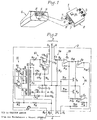
- the accessory 1 shown in FIG. 1 comprises a housing 2, of approximately parallelepiped shape, on the rear face of which is disposed a first group 3 of three terminals X, Y and Z, and on the front face of which is fixed a male connector 4 constituting a second group of terminals of the accessory 1.
- Terminal X is intended to be connected by a conductor (not shown) to an earth connection whose resistance is to be measured.
- Terminal Y is intended to be connected by a conductor (not shown) to an auxiliary reference earth potential socket.
- Terminal Z is intended to be connected by a conductor (not shown) to a socket for injecting current into the ground.
- the three aforementioned sockets can be constituted in a known manner by ground stakes.
- the male connector 4 can be plugged into a female connector 5 of a multimeter 6 such as, for example, a digital multimeter model "CONPA 2010" or "CONPA 2011” from the Company Chauvin Arnoux.
- a multimeter 6 such as, for example, a digital multimeter model "CONPA 2010" or "CONPA 2011” from the Company Chauvin Arnoux.
- Two indexing pins 7, each provided with an axial hole 8, protrude from the front face of the housing 2 on either side of the male connector 4.
- the two pins 7 and leuJS holes 8 can be engaged respectively in cavities 9, provided with pins 10, which are provided in the multimeter housing 6 on either side of the female connector 5.
- the pins 7 allow the adaptation of the housing 2 - of the accessory 1 to the housing of the multimeter 6 and at the same time, they position the contact pins of the male connector 4 relative to the contact sockets of the female connector 5, thus facilitating the insertion of the male connector 4 into the female connector 5 when the accessory 1 is mounted on the multimeter 6 .
- the multimeter contains, in known manner, a supply battery (not shown), the positive and negative terminals of which are respectively connected to two of the terminals or sockets of the female connector 5. Two other terminals or sockets of the female connector 5 serve as terminals d input for a DC signal whose voltage is to be measured, when the switch-selector for calibers and functions of the multimeter is in a position corresponding to a DC-voltage measurement.
- FIG 2 there is shown the electrical circuits of the accessory 1.
- the latter essentially comprises, on the one hand, an oscillator circuit 11, a transformer 12 and a current regulator 13, which together form an alternating current generator constant, and, on the other hand, a filter 14, a buffer amplifier 15 and a synchronous detector 16, which process the measurement signal before it is applied to the multimeter 6.
- the oscillator 11 comprises two transistors npn Q 1 and Q 2 , the collectors of which are connected respectively to the ends of the primary winding P 1 at the midpoint of the transformer 12, the midpoint of the winding P 1 being connected through a switch. 17 to the terminal B 1 of the male connector 4 which is connected via the female connector 5 to the positive terminal of the multimeter battery 6.
- the switch 17 is for example of the push button type 1 8, the latter being accessible on the upper face of the housing 2 of the accessory 1 (FIG. 1).
- the emitters of t ran- s istors Q1 and Q2 are connected directly to the terminal B 2 of the male connector 4 which is connected via the female connector 5 to the negative terminal of the battery tester 6.
- the bases of transistors Q 1 and Q 2 are respectively connected to the ends of the reaction winding P 2 at the midpoint of the transformer 12.
- the midpoint of the winding P 2 is connected to the junction point between two resistors R 1 and R 2 which are connected in series between terminals B 1 and B 2 and which form a voltage divider for the polarization of the bases of transistors Q 1 and Q 2 .
- a capacitor C 1 and a resistor R 3 are connected in series between the ends of the primary winding P 1 of the transformer 12.
- the windings P 1 and P 2 ; the transistors Q 1 and Q 2 , the capacitor C 1 and the resistor R 3 form a symmetrical relaxation oscillator of a known type.
- the oscillation frequency is defined by the magnetic characteristics of the transformer core 12, the inductance of the winding P 1. , The capacity of the capacitor C 1 and the voltage of the supply battery.
- the components are chosen in such a way that the oscillation frequency is in the range from 130 to 230 Hz which is favorable for the measurement of earth resistances.
- the oscillation frequency must however be chosen different from 150 and 200 Hertz, that is to say different from the harmonics of the sector.
- the current regulator circuit 13 comprises an npn transistor Q 3 and a pnp transistor Q 4 , the emitters of which are connected through two resistors in series R 4 and R 5 at one of the ends of the secondary winding S 1 of the transformer 12.
- the bases of the transistors Q 3 and Q 4 are connected on the one hand to the abovementioned end of the secondary winding S 1 through two Zener diodes CR 1 and CR 2 mounted in opposition and, on the other hand, to the other end of the secondary winding S 1 through a resistor R 6 .
- the collector of transistor Q 3 is connected to the cathode of a diode CR 3 the anode of which is connected to terminal Z through a resistor (not designated), while the collector of transistor Q 4 is connected to the anode a CR 4 diode whose cathode is connected to the Z terminal through said resistor.
- Said other end of the secondary winding S 1 of the transformer 12 is connected directly on the one hand to the terminal X of the group 3 of three terminals and, on the other hand, to the output terminal U 1 of the male connector 4.
- the filter 14 is constituted by a capacitor C 4 , one of the armatures of which is connected to the terminal Y of group 3 of three terminals and the other armature of which is connected through a resistor R 7 to the terminal X.
- the point of junction between capacitor C 4 and resistor R 7 is connected through a resistor R a to the input + of an operational amplifier A 1 whose output is connected on the one hand to the input - of amplifier A 1 through a resistor R 9 and, on the other hand, at the input of the synchronous detector 16.
- the synchronous detector 16 essentially comprises two operational amplifiers A 2 and A 3 and two field effect transistors Q 5 and Q 6 , respectively with N channel and with P channel.
- the transistors Q 5 and Q 6 are controlled by the alternating current signal available at the ends of the secondary winding S 1 of the transformer 12.
- the gates of the two transistors Q 5 and Q 6 are connected, respectively through resistors R 10 and R 11 ' at the junction point between resistor R 4 and secondary winding S 3 .
- the output of the operational amplifier A 1 is connected on the one hand through a resistor R 12 to the input + of the operational amplifier A 2 and, on the other hand, through resistors R 13 and R 14 mounted in series, at the input - of the operational amplifier A 3 .
- the input + of the operational amplifier A 2 is connected to the terminal X through the source-drain path of the transistor Q 6 when the latter is on.
- the output of the operational amplifier A 2 is connected on the one hand directly to its input - and, on the other hand, through a resistor R 15 to the terminal U 2 of the male connector 4.
- the + input of the operational amplifier A 3 is connected directly to terminal X, while its input - is connected to terminal X through resistor R14 and through the source-drain path of transistor Q 5 when it is on.
- the output of the operational amplifier A 3 is connected on the one hand through the resistor R 16 to its input - and, on the other hand, through the resistor R 37 at the terminal U 2 .
- the transformer 12 includes a second secondary winding S 2 one of whose ends is connected to the end of the secondary winding S 1 which is itself connected to the terminals X and U 1. And the other end of which is connected to the cathode of a CR 5 diode and to the anode of a CR 6 diode. These two diodes supply, after filtering by the capacitors C 2 and C 3 , the DC voltages - Va and + Va necessary for the operation of the operational amplifiers A 3 , A 2 and A3.
- the alternating current which is injected by the terminal Z into the earth whose resistance is to be measured is regulated in amplitude by the transistors Q 3 and Q 4 associated with the Zener CR diodes 1 and CR 2 and resistors R 4 and R 5 .
- Resistance R 5 is an adjustable resistor to allow precise adjustment of the value of the constant alternating current which is injected into the earth by terminal Z. Indeed, the value of this current determines the ratio between the output voltage and the earth resistance to measure.
- this ratio is 1 mV / ohm, thus making it possible to directly read the value of the resistance in ohms on the 100 mV rating of the multimeter and this value in kohmss on the 1 V rating of the multimeter.
- the operational amplifier A is connected to the + input in voltage follower so as to have a high input impedance.
- This high input impedance makes the measurement of the earth resistance independent of the resistance of the reference earth potential auxiliary tap. Consequently, as the current I injected into the earth by the terminal Z is constant and as the above-mentioned ratio between output voltage and resistance to be measured is 1 mV / ohm, the voltage RI taken between the terminals X and Y constitutes a measurement resistance R of the earth to be measured.
- the high input impedance of the operational amplifier A allows resistances of the auxiliary tap of the reference earth potential (terminal Y) of several kohms, without appreciable disturbance of the measurement.
- the field effect transistors Q 5 and Q 6 associated with the operational amplifiers A 2 and A 3 carry out a synchronous rectification of the voltage taken at the terminals X and Y.
- the resistors R 15 and R 17 sum the unidirectional alternations originating from the amplifiers A 2 and A 3 .
- the galvanic isolation provided by the transformer 12 between the multimeter's supply battery and the output terminals U and U 2 makes it possible to connect the latter to the multimeter without disturbing the operation of the latter.
- the components of the circuits shown in FIG. 2 can be the following:
- the housing 2 will not have the male connector 4 and the plugs 7. Instead, the housing 2 will have two terminals (the output terminals U 1 and U 2 ) in the form of sockets can be connected to the multimeter's input terminals by connecting conductors.
- a battery pack must be provided inside the accessory case.
Landscapes
- Physics & Mathematics (AREA)
- General Physics & Mathematics (AREA)
- Measurement Of Current Or Voltage (AREA)
- Measurement Of Resistance Or Impedance (AREA)
Priority Applications (1)
| Application Number | Priority Date | Filing Date | Title |
|---|---|---|---|
| AT83402180T ATE16857T1 (de) | 1982-11-10 | 1983-11-10 | Mit einem vielfachmessgeraet verbindbares zusatzgeraet zum messen von erdungswiderstaenden. |
Applications Claiming Priority (2)
| Application Number | Priority Date | Filing Date | Title |
|---|---|---|---|
| FR8218860A FR2535850A1 (fr) | 1982-11-10 | 1982-11-10 | Accessoire pouvant etre connecte a un multimetre pour la mesure de resistances de terre |
| FR8218860 | 1982-11-10 |
Publications (2)
| Publication Number | Publication Date |
|---|---|
| EP0112200A1 true EP0112200A1 (de) | 1984-06-27 |
| EP0112200B1 EP0112200B1 (de) | 1985-12-04 |
Family
ID=9279077
Family Applications (1)
| Application Number | Title | Priority Date | Filing Date |
|---|---|---|---|
| EP83402180A Expired EP0112200B1 (de) | 1982-11-10 | 1983-11-10 | Mit einem Vielfachmessgerät verbindbares Zusatzgerät zum Messen von Erdungswiderständen |
Country Status (5)
| Country | Link |
|---|---|
| US (1) | US4590421A (de) |
| EP (1) | EP0112200B1 (de) |
| AT (1) | ATE16857T1 (de) |
| DE (1) | DE3361439D1 (de) |
| FR (1) | FR2535850A1 (de) |
Cited By (1)
| Publication number | Priority date | Publication date | Assignee | Title |
|---|---|---|---|---|
| GB2191591A (en) * | 1986-06-10 | 1987-12-16 | Kenure Developments Limited | Earth monitoring |
Families Citing this family (4)
| Publication number | Priority date | Publication date | Assignee | Title |
|---|---|---|---|---|
| RU2201477C1 (ru) * | 2002-01-14 | 2003-03-27 | Акционерное общество открытого типа "Всероссийский алюминиево-магниевый институт" | Способ контроля сопротивления изоляции между электролизером и землёй и устройство для его осуществления |
| USD642082S1 (en) * | 2009-09-18 | 2011-07-26 | Abb Technology Ag | Capacitance meter |
| US9360507B2 (en) * | 2011-12-19 | 2016-06-07 | Tyco Safety Products Canada Ltd. | Displacement tamper sensor and method |
| CN112180200B (zh) * | 2020-10-27 | 2025-02-28 | 河北京车轨道交通车辆装备有限公司 | 一种160公里市域动车组mvb车辆总线调试工装 |
Family Cites Families (6)
| Publication number | Priority date | Publication date | Assignee | Title |
|---|---|---|---|---|
| US3501694A (en) * | 1967-05-18 | 1970-03-17 | Hewlett Packard Yokogawa | Ohmmeter circuit having stabilizing circuit which reduces the effect of source variations on indication |
| JPS547487Y2 (de) * | 1974-04-21 | 1979-04-07 | ||
| US4209741A (en) * | 1978-03-08 | 1980-06-24 | The United States Of America As Represented By The Secretary Of The Interior | Apparatus for the continuous monitoring of ground bed resistance |
| US4200835A (en) * | 1978-05-30 | 1980-04-29 | Fuji Electric Co., Ltd. | Method and apparatus for measuring the insulation resistance of an operating grounded transmission line system |
| FR2492535A1 (fr) * | 1980-10-17 | 1982-04-23 | Onera (Off Nat Aerospatiale) | Resistivimetre de surface |
| US4415850A (en) * | 1981-02-12 | 1983-11-15 | Amf Incorporated | Ground conductor monitoring system |
-
1982
- 1982-11-10 FR FR8218860A patent/FR2535850A1/fr active Granted
-
1983
- 1983-11-07 US US06/549,457 patent/US4590421A/en not_active Expired - Fee Related
- 1983-11-10 AT AT83402180T patent/ATE16857T1/de not_active IP Right Cessation
- 1983-11-10 DE DE8383402180T patent/DE3361439D1/de not_active Expired
- 1983-11-10 EP EP83402180A patent/EP0112200B1/de not_active Expired
Non-Patent Citations (5)
| Title |
|---|
| BBC-NACHRICHTEN, vol. 54, septembre/octobre 1972, pages 241-252, Mannheim, DE * |
| ELEKTRONIK, vol. 18, no. 5, mei 1969, pages 135-137, Munich, DE * |
| HEWLETT-PACKARD JOURNAL, vol. 28, no. 1, septembre 1976, pages 9-15, Palo Alto, US * |
| MESSEN UND PRÜFEN, no. 5, mai 1980, pages 306-308, Woerishofen, DE * |
| RADIOMENTOR ELECTRONIC, vol. 44, février 1978, pages 70-71, Munich, DE * |
Cited By (1)
| Publication number | Priority date | Publication date | Assignee | Title |
|---|---|---|---|---|
| GB2191591A (en) * | 1986-06-10 | 1987-12-16 | Kenure Developments Limited | Earth monitoring |
Also Published As
| Publication number | Publication date |
|---|---|
| ATE16857T1 (de) | 1985-12-15 |
| FR2535850A1 (fr) | 1984-05-11 |
| FR2535850B1 (de) | 1985-04-19 |
| EP0112200B1 (de) | 1985-12-04 |
| US4590421A (en) | 1986-05-20 |
| DE3361439D1 (en) | 1986-01-16 |
Similar Documents
| Publication | Publication Date | Title |
|---|---|---|
| CA1182537A (fr) | Capteur dynamique de courant | |
| US5598098A (en) | Electronic battery tester with very high noise immunity | |
| EP0399923B1 (de) | Verfahren zur Korrektur des Phasenfehlers bei der Messung eines Fehlerstromes mit einem symmetrischen Ringkern | |
| FR2706041A1 (fr) | Détecteur de courant pour dispositifs médicaux incluant des câbles de connexion. | |
| EP0297933A1 (de) | Anordnung zur Kontrolle und zur Messung der Isolierung eines elektrischen Netzes | |
| WO2000045183A3 (en) | Electrical energy meter | |
| FR2766304A1 (fr) | Circuit d'alimentation pour un compteur d'electricite | |
| Filipski et al. | AC-DC current shunts and system for extended current and frequency ranges | |
| FR3019304A1 (fr) | Procede de mesure de la consommation energetique des branches d'un reseau electrique et equipement de mesure mettant en oeuvre ledit procede | |
| FR2584195A1 (fr) | Pince amperemetrique a effet hall | |
| EP0112200B1 (de) | Mit einem Vielfachmessgerät verbindbares Zusatzgerät zum Messen von Erdungswiderständen | |
| EP0493271B1 (de) | Messbrücke für Referenzspannung für Gerät zur Überwachung und Messung der Isolation eines elektrischen Gleichspannungsnetzes | |
| FR2460576A1 (fr) | Circuit d'alimentation a trois bornes pour appareil telephonique | |
| FR2670295A1 (fr) | Dispositif de mesure electrique a double configuration de branchement. | |
| FR3105430A1 (fr) | Dispositif de detection d'une defaillance dans un reseau electrique, reseau electrique ou equipement comprenant un tel dispositif et procede de detection d’une defaillance | |
| CA1206525A (fr) | Circuit d'alimentation d'une sonde a courants de foucault | |
| EP0722092A1 (de) | Testanordnung für ein mit amagnetischen Fühlern verbundenes Sicherheitsrelais | |
| EP0549444A1 (de) | Elektronische Vorrichtung zur Multiplexierung verschiedener mit Wechselstrom gespeisster Läste | |
| Karunathilaka et al. | Faradaic impedance measurements of small magnitudes encountered in high capacity electrical storage cells | |
| FR2547104A1 (fr) | Transformateur de tension de haute precision | |
| JPS6454379A (en) | Probe substrate for measuring semiconductor integrated circuit | |
| JPH0313742Y2 (de) | ||
| EP0103520B1 (de) | Eingangs- und Speisungsschaltung für einen Filter, insbesondere einen Filter für einen Rundsteuerungsempfänger | |
| EP4089422B1 (de) | Vorrichtung und verfahren zur schätzung der isolationsimpedanz eines tt- oder tn-netzes | |
| FR2826217A1 (fr) | Dispositif de detection de prise de ligne telephonique |
Legal Events
| Date | Code | Title | Description |
|---|---|---|---|
| PUAI | Public reference made under article 153(3) epc to a published international application that has entered the european phase |
Free format text: ORIGINAL CODE: 0009012 |
|
| 17P | Request for examination filed |
Effective date: 19840407 |
|
| AK | Designated contracting states |
Designated state(s): AT DE GB IT |
|
| ITF | It: translation for a ep patent filed | ||
| GRAA | (expected) grant |
Free format text: ORIGINAL CODE: 0009210 |
|
| AK | Designated contracting states |
Designated state(s): AT DE GB IT |
|
| REF | Corresponds to: |
Ref document number: 16857 Country of ref document: AT Date of ref document: 19851215 Kind code of ref document: T |
|
| REF | Corresponds to: |
Ref document number: 3361439 Country of ref document: DE Date of ref document: 19860116 |
|
| PLBE | No opposition filed within time limit |
Free format text: ORIGINAL CODE: 0009261 |
|
| STAA | Information on the status of an ep patent application or granted ep patent |
Free format text: STATUS: NO OPPOSITION FILED WITHIN TIME LIMIT |
|
| PG25 | Lapsed in a contracting state [announced via postgrant information from national office to epo] |
Ref country code: AT Effective date: 19861110 |
|
| 26N | No opposition filed | ||
| PG25 | Lapsed in a contracting state [announced via postgrant information from national office to epo] |
Ref country code: DE Effective date: 19870801 |
|
| PGFP | Annual fee paid to national office [announced via postgrant information from national office to epo] |
Ref country code: GB Payment date: 19901023 Year of fee payment: 8 |
|
| PG25 | Lapsed in a contracting state [announced via postgrant information from national office to epo] |
Ref country code: GB Effective date: 19911110 |
|
| GBPC | Gb: european patent ceased through non-payment of renewal fee |