EP0112220A2 - Schleifscheibe - Google Patents
Schleifscheibe Download PDFInfo
- Publication number
- EP0112220A2 EP0112220A2 EP83402287A EP83402287A EP0112220A2 EP 0112220 A2 EP0112220 A2 EP 0112220A2 EP 83402287 A EP83402287 A EP 83402287A EP 83402287 A EP83402287 A EP 83402287A EP 0112220 A2 EP0112220 A2 EP 0112220A2
- Authority
- EP
- European Patent Office
- Prior art keywords
- grinding wheel
- support
- elements
- wheel according
- abrasive strip
- Prior art date
- Legal status (The legal status is an assumption and is not a legal conclusion. Google has not performed a legal analysis and makes no representation as to the accuracy of the status listed.)
- Withdrawn
Links
Images
Classifications
-
- B—PERFORMING OPERATIONS; TRANSPORTING
- B24—GRINDING; POLISHING
- B24D—TOOLS FOR GRINDING, BUFFING OR SHARPENING
- B24D7/00—Bonded abrasive wheels, or wheels with inserted abrasive blocks, designed for acting otherwise than only by their periphery, e.g. by the front face; Bushings or mountings therefor
- B24D7/16—Bushings; Mountings
-
- B—PERFORMING OPERATIONS; TRANSPORTING
- B24—GRINDING; POLISHING
- B24D—TOOLS FOR GRINDING, BUFFING OR SHARPENING
- B24D5/00—Bonded abrasive wheels, or wheels with inserted abrasive blocks, designed for acting only by their periphery; Bushings or mountings therefor
- B24D5/16—Bushings; Mountings
-
- B—PERFORMING OPERATIONS; TRANSPORTING
- B24—GRINDING; POLISHING
- B24D—TOOLS FOR GRINDING, BUFFING OR SHARPENING
- B24D7/00—Bonded abrasive wheels, or wheels with inserted abrasive blocks, designed for acting otherwise than only by their periphery, e.g. by the front face; Bushings or mountings therefor
- B24D7/10—Bonded abrasive wheels, or wheels with inserted abrasive blocks, designed for acting otherwise than only by their periphery, e.g. by the front face; Bushings or mountings therefor with cooling provisions
Definitions
- the invention relates to a grinding wheel comprising an annular abrasive strip carried by a support in the form of a body of revolution.
- the strip impregnated with abrasive particles is permanently bonded or brazed to a support ensuring mounting on a rotational spindle. After wear of the abrasive band, the support cannot be reused for a new use, it is lost and must be discarded.
- the invention relates to a grinding wheel whose support consists of two elements; these can be juxtaposed on the same axis of revolution and their circular edges are shaped so as to be able to receive and, after mutual tightening of said juxtaposed elements, subjecting the abrasive strip, pinched in a centered position on said axis, produced in the form of an autonomous piece.
- the grinding wheel according to the invention comprises an abrasive strip not permanently fixed to its support, but removable and held by simple clamping between the two elements of the support. It can therefore be replaced after wear, or during wear, either with a new iden- strip. tick, or by a strip having other abrasive characteristics.
- the wheel support can be reused indefinitely, so that the use of the wheel according to the invention provides substantial savings.
- the abrasive strip and said support elements have conjugate annular surfaces by which the abrasive strip is secured by pinching.
- the gripping surface offered by at least one of the elements of the support can be either a flat surface and orthogonal to the axis of the grinding wheel, or a conical surface of the same axis as the grinding wheel. All of the two elements constituting the- support of the strip may therefore have gripping surfaces, either both flat, or both conical, or one flat and the other conical.
- at least one of the gripping surfaces belonging to said elements may include a relief for centering the abrasive strip, which is useful mainly in the case of flat gripping surfaces.
- a grinding wheel according to the invention can have the shape of a cup wheel; the support elements then have the shape of a bowl and are nestable one inside the other, the abrasive strip having an internal rim which is gripped between the terminal edge of the external element and an external peripheral rim that includes the inner element of the support.
- the gripping surface offered by the peripheral rim of the interior element is hollowed out with substantially radial grooves which allow the cutting liquid, introduced via the drive spindle - hollow - on which the grinding wheel is mounted and holes drilled in this spindle at the intermediate space separating the two support elements, reaching, passing through this space where it is brought to the grinding speed, the active part of the abrasive strip.
- a grinding wheel according to the invention can also have the shape of a cylindrical grinding wheel; the elements of the support then have the form of discs between the edges of which is taken by pinching the abrasive strip.
- the support elements are constituted by identical discs having conically chamfered edges, combined with a conical nip surface which the abrasive strip comprises.
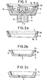
- Figure 1 shows, in axial section, a cup wheel according to the invention mounted on a rotation spindle.
- FIGS 2a to 2c respectively represent each of the three constituent parts of the grinding wheel of Figure 1.
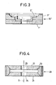
- FIG. 3 represents, in axial section, a cup wheel according to the invention offering a different conformation:
- Figure 4 shows, in axial section, a cylindrical grinding wheel according to the invention.
- FIGS. 1 and 2a to 2c show a cup wheel 10 according to the invention, comprising three distinct constituent parts: an external element 1, an internal element 2 and a strip 3 comprising an abrasive part 3a.
- Elements 1 and 2 made of bakelite, metal or bakelite-aluminum compound, have the shape of a flat-bottomed bowl pierced with a respective central hole 4.5 which allows mounting on a drive pin 6 in rotation.
- the strip 3, in one piece like the elements 1 and 2 has an internal rim 3b showing two annular surfaces 7,8 contained in planes perpendicular to the axis of revolution 9 of the grinding wheel 10 and of its constituent parts 1,2 and 3. This rim allows the fixing of the strip 3 to the elements 1 and 2 which constitute its support, by pinching between the terminal edge of the element 1 and an external rim 2a offered by the element 2.
- the surface 8 of the strip 3 is placed in contact with the mating surface 11 of the end edge of the element 1, the centering of the strip being ensured by a circular projection 12 internally limiting the surface 11.
- the element 2 is fitted into the element 1, the surface .13 of its rim 2a coming to be applied on the surface 7 of the strip 3.
- the assembly is then engaged on the spindle 6 and a firm connection of the strip 3 to the support elements 1 and 2 is effected by tightening these by means of a nut 14 screwed onto the threaded end 6a of the spindle 6.
- Figure 1 shows that the drive spindle 6 is hollow and has an internal channel 15 which does not extend into the threaded end 6a, but opens through radial holes 16 in the space 17 separating the flat bottoms of the elements 1 and 2.
- the contact surface 13 of the rim 2a of the element 2 is hollowed out with radial grooves 18.
- FIG 3 shows by way of example a cup wheel 10 'which, although of different conformation, has the same structure as the wheel 10, also being composed of a removable strip 3' held by pinching between two support elements 1 'and 2'. Any other form of cup wheel, standardized or not, can also be produced in accordance with the teaching of the present invention.
- the two elements 21 and 22 of the support take the form of identical flat discs, drilled centrally with mounting holes 24 and 25, the peripheral edges offer conically chamfered surfaces between which the strip 23 is pinched by conjugate conical surfaces which it comprises. These conical contact surfaces themselves center the strip around the axis 9.
Landscapes
- Engineering & Computer Science (AREA)
- Mechanical Engineering (AREA)
- Polishing Bodies And Polishing Tools (AREA)
Applications Claiming Priority (2)
| Application Number | Priority Date | Filing Date | Title |
|---|---|---|---|
| FR8220136A FR2537034B1 (fr) | 1982-12-01 | 1982-12-01 | Meule |
| FR8220136 | 1982-12-01 |
Publications (2)
| Publication Number | Publication Date |
|---|---|
| EP0112220A2 true EP0112220A2 (de) | 1984-06-27 |
| EP0112220A3 EP0112220A3 (de) | 1985-12-04 |
Family
ID=9279692
Family Applications (1)
| Application Number | Title | Priority Date | Filing Date |
|---|---|---|---|
| EP83402287A Withdrawn EP0112220A3 (de) | 1982-12-01 | 1983-11-28 | Schleifscheibe |
Country Status (2)
| Country | Link |
|---|---|
| EP (1) | EP0112220A3 (de) |
| FR (1) | FR2537034B1 (de) |
Cited By (5)
| Publication number | Priority date | Publication date | Assignee | Title |
|---|---|---|---|---|
| EP0530536A1 (de) * | 1991-09-02 | 1993-03-10 | Tyrolit Schleifmittelwerke Swarovski KG | Schleifteller |
| WO2005023490A1 (de) | 2003-09-04 | 2005-03-17 | Gerhard Schrottner | Ringsystem zur mediumsführung bei schleifscheiben |
| CN1994677B (zh) * | 2006-01-05 | 2011-05-04 | 鸿富锦精密工业(深圳)有限公司 | 砂轮装置 |
| EP2949424A1 (de) * | 2014-05-30 | 2015-12-02 | Tenryu Saw Mfg. Co., Ltd. | Topfschleifscheibe |
| IT201700110864A1 (it) * | 2017-10-04 | 2019-04-04 | Saidtools Srl | Utensile per affilatura |
Families Citing this family (4)
| Publication number | Priority date | Publication date | Assignee | Title |
|---|---|---|---|---|
| JP5465257B2 (ja) * | 2010-01-13 | 2014-04-09 | 株式会社アライドマテリアル | 超砥粒ホイール、その使用方法およびそれを用いたウエハの製造方法ならびにウエハ |
| CN110355621B (zh) * | 2019-07-17 | 2021-03-16 | 大连理工大学 | 一种用于超声加工的组合砂轮及其设计方法 |
| CN110328573A (zh) * | 2019-08-09 | 2019-10-15 | 蚌埠市昆宇机械加工厂 | 一种玻璃边部磨边装置 |
| CN110385633A (zh) * | 2019-08-12 | 2019-10-29 | 蚌埠市昆宇机械加工厂 | 一种玻璃表面抛光装置 |
Family Cites Families (14)
| Publication number | Priority date | Publication date | Assignee | Title |
|---|---|---|---|---|
| FR745444A (de) * | 1933-05-10 | |||
| US1710528A (en) * | 1925-06-23 | 1929-04-23 | Carborundum Co | Grinding wheel and holder therefor |
| US1953181A (en) * | 1931-09-21 | 1934-04-03 | Edmund J Lintereur | Grinding wheel construction |
| FR45734E (fr) * | 1934-12-24 | 1935-11-18 | Emil Offenbacher A G | Disques d'affûtage coupeurs |
| FR991855A (fr) * | 1949-05-20 | 1951-10-11 | Meule à polir | |
| DE804071C (de) * | 1950-02-19 | 1951-04-16 | Karl Eckel | Vorrichtung fuer Schleifboecke zum schnellen Wechseln des Schleifbelages |
| US2626493A (en) * | 1952-08-13 | 1953-01-27 | Alfred R Conti | Abrasive wheel coolant spraying spindle |
| US2823496A (en) * | 1953-03-16 | 1958-02-18 | Otto W Winter | Grinding devices |
| FR1232118A (fr) * | 1959-08-06 | 1960-10-05 | Perfectionnements apportés aux dispositifs de montage d'outils abrasifs rotatifs | |
| FR1265760A (fr) * | 1960-08-24 | 1961-06-30 | Machine pour le travail des pierres et des briques | |
| US3636665A (en) * | 1970-04-15 | 1972-01-25 | Grinding Wheel Inst Inc | Segmented grinding wheel |
| DE2500626A1 (de) * | 1975-01-09 | 1976-07-15 | Lohmann Dr Artifex | Topffoermige schleif- oder polierscheibe |
| IN155783B (de) * | 1980-04-02 | 1985-03-09 | De Beers Ind Diamond | |
| US4393626A (en) * | 1981-11-09 | 1983-07-19 | Cincinnati Milacron Inc. | Toolholder for supporting thin rotary tools |
-
1982
- 1982-12-01 FR FR8220136A patent/FR2537034B1/fr not_active Expired
-
1983
- 1983-11-28 EP EP83402287A patent/EP0112220A3/de not_active Withdrawn
Cited By (7)
| Publication number | Priority date | Publication date | Assignee | Title |
|---|---|---|---|---|
| EP0530536A1 (de) * | 1991-09-02 | 1993-03-10 | Tyrolit Schleifmittelwerke Swarovski KG | Schleifteller |
| WO2005023490A1 (de) | 2003-09-04 | 2005-03-17 | Gerhard Schrottner | Ringsystem zur mediumsführung bei schleifscheiben |
| AT502503B1 (de) * | 2003-09-04 | 2007-04-15 | Schrottner Gerhard | Ringsystem zur mediumsführung bei schleifscheiben |
| CN1994677B (zh) * | 2006-01-05 | 2011-05-04 | 鸿富锦精密工业(深圳)有限公司 | 砂轮装置 |
| EP2949424A1 (de) * | 2014-05-30 | 2015-12-02 | Tenryu Saw Mfg. Co., Ltd. | Topfschleifscheibe |
| IT201700110864A1 (it) * | 2017-10-04 | 2019-04-04 | Saidtools Srl | Utensile per affilatura |
| EP3466609A1 (de) * | 2017-10-04 | 2019-04-10 | Saidtools S.R.L. | Schärfwerkzeug |
Also Published As
| Publication number | Publication date |
|---|---|
| FR2537034A1 (fr) | 1984-06-08 |
| EP0112220A3 (de) | 1985-12-04 |
| FR2537034B1 (fr) | 1987-01-16 |
Similar Documents
| Publication | Publication Date | Title |
|---|---|---|
| EP1194943B1 (de) | Kontaktfeder für sicherungshalter und damit versehener sicherungshalter | |
| EP0112220A2 (de) | Schleifscheibe | |
| EP0677671A1 (de) | Einheit mit einem Schrägkugellager und ihre Anwendung in einer Lenkungsanlage eines Fahrzeuges | |
| CA1264563A (fr) | Dispositif de solidarisation ou de desolidarisation rapide, a des fins d'antivol, du volant et de la colonne de direction d'un vehicule automobile | |
| EP0203850B1 (de) | Einrichtung zum schnellen Verbinden oder Lösen des Lenkrades und der Lenksäule eines Kraftfahrzeuges zwecks Diebstahlsicherung | |
| FR2770597A1 (fr) | Procede de fabrication d'une bague interieure d'une rotule metallique, et rotule ainsi realisee | |
| FR2785561A1 (fr) | Compresseur de ressort pour ressorts helicoidaux avec au moins un disque de ressort | |
| EP1632311A1 (de) | Stabpoliermaschine mit auswechselbarem Polierkopf | |
| FR2536688A1 (fr) | Dispositif pour monter des outils abrasifs de facon amovible sur l'arbre d'une machine de meulage | |
| EP0484215B1 (de) | Druckfedernspanner | |
| WO1998024351A1 (fr) | Couvercle a bouton de prehension | |
| EP3037895B1 (de) | Ausbaubarer Spiralklötzchenträger | |
| FR2661286A1 (fr) | Dispositif repartiteur de puissance comprenant un corps de support d'un certain nombre de connecteurs coaxiaux de dimensions differentes. | |
| EP4188253B1 (de) | Osteosynthesevorrichtung mit mindestens einem fixationsstift | |
| FR2668244A1 (fr) | Moyens pour relier ensemble deux cadres. | |
| FR3058389B1 (fr) | Dispositif de montage d'un axe sur une chape | |
| EP1201957A1 (de) | Radbaugruppe mit einer Scheibenbremse für Fahrzeuge | |
| WO2026087360A1 (fr) | Dispositif de protection de flanc de pneu muni d'une pièce d'adaptation | |
| FR2832672A1 (fr) | Moyeu de roue et roue ayant un tel moyeu | |
| FR2670069A3 (fr) | Couverture de protection de haut-parleurs. | |
| FR2662474A1 (fr) | Ecrou rapide demontable. | |
| FR2556056A1 (fr) | Moyen d'assemblage de tubes notamment pour la realisation de cadres de bicyclettes | |
| EP4296790A1 (de) | Spiralklötzchenträgervorrichtung | |
| BE701222A (de) | ||
| CH716869A2 (fr) | Dispositif de fixation à rotule. |
Legal Events
| Date | Code | Title | Description |
|---|---|---|---|
| PUAI | Public reference made under article 153(3) epc to a published international application that has entered the european phase |
Free format text: ORIGINAL CODE: 0009012 |
|
| 17P | Request for examination filed |
Effective date: 19831129 |
|
| AK | Designated contracting states |
Designated state(s): AT BE CH DE GB IT LI LU NL SE |
|
| PUAL | Search report despatched |
Free format text: ORIGINAL CODE: 0009013 |
|
| AK | Designated contracting states |
Designated state(s): AT BE CH DE GB IT LI LU NL SE |
|
| STAA | Information on the status of an ep patent application or granted ep patent |
Free format text: STATUS: THE APPLICATION HAS BEEN WITHDRAWN |
|
| 18W | Application withdrawn |
Withdrawal date: 19860527 |
|
| RIN1 | Information on inventor provided before grant (corrected) |
Inventor name: VINCENT, JEAN-LOUIS CHARLES JEROME |