EP0112320A2 - Einrichtung zum Profilieren einer Schleifscheibe - Google Patents
Einrichtung zum Profilieren einer Schleifscheibe Download PDFInfo
- Publication number
- EP0112320A2 EP0112320A2 EP83870127A EP83870127A EP0112320A2 EP 0112320 A2 EP0112320 A2 EP 0112320A2 EP 83870127 A EP83870127 A EP 83870127A EP 83870127 A EP83870127 A EP 83870127A EP 0112320 A2 EP0112320 A2 EP 0112320A2
- Authority
- EP
- European Patent Office
- Prior art keywords
- tools
- cutting
- dressing
- barrel
- profiling
- Prior art date
- Legal status (The legal status is an assumption and is not a legal conclusion. Google has not performed a legal analysis and makes no representation as to the accuracy of the status listed.)
- Withdrawn
Links
Images


Classifications
-
- B—PERFORMING OPERATIONS; TRANSPORTING
- B24—GRINDING; POLISHING
- B24B—MACHINES, DEVICES, OR PROCESSES FOR GRINDING OR POLISHING; DRESSING OR CONDITIONING OF ABRADING SURFACES; FEEDING OF GRINDING, POLISHING, OR LAPPING AGENTS
- B24B53/00—Devices or means for dressing or conditioning abrasive surfaces
- B24B53/12—Dressing tools; Holders therefor
-
- B—PERFORMING OPERATIONS; TRANSPORTING
- B24—GRINDING; POLISHING
- B24B—MACHINES, DEVICES, OR PROCESSES FOR GRINDING OR POLISHING; DRESSING OR CONDITIONING OF ABRADING SURFACES; FEEDING OF GRINDING, POLISHING, OR LAPPING AGENTS
- B24B27/00—Other grinding machines or devices
- B24B27/0061—Other grinding machines or devices having several tools on a revolving tools box
-
- B—PERFORMING OPERATIONS; TRANSPORTING
- B24—GRINDING; POLISHING
- B24B—MACHINES, DEVICES, OR PROCESSES FOR GRINDING OR POLISHING; DRESSING OR CONDITIONING OF ABRADING SURFACES; FEEDING OF GRINDING, POLISHING, OR LAPPING AGENTS
- B24B53/00—Devices or means for dressing or conditioning abrasive surfaces
-
- Y—GENERAL TAGGING OF NEW TECHNOLOGICAL DEVELOPMENTS; GENERAL TAGGING OF CROSS-SECTIONAL TECHNOLOGIES SPANNING OVER SEVERAL SECTIONS OF THE IPC; TECHNICAL SUBJECTS COVERED BY FORMER USPC CROSS-REFERENCE ART COLLECTIONS [XRACs] AND DIGESTS
- Y10—TECHNICAL SUBJECTS COVERED BY FORMER USPC
- Y10T—TECHNICAL SUBJECTS COVERED BY FORMER US CLASSIFICATION
- Y10T408/00—Cutting by use of rotating axially moving tool
- Y10T408/36—Machine including plural tools
- Y10T408/37—Turret of tools
-
- Y—GENERAL TAGGING OF NEW TECHNOLOGICAL DEVELOPMENTS; GENERAL TAGGING OF CROSS-SECTIONAL TECHNOLOGIES SPANNING OVER SEVERAL SECTIONS OF THE IPC; TECHNICAL SUBJECTS COVERED BY FORMER USPC CROSS-REFERENCE ART COLLECTIONS [XRACs] AND DIGESTS
- Y10—TECHNICAL SUBJECTS COVERED BY FORMER USPC
- Y10T—TECHNICAL SUBJECTS COVERED BY FORMER US CLASSIFICATION
- Y10T483/00—Tool changing
- Y10T483/15—Tool changing with means to condition or adjust tool or tool support
Definitions
- the present invention relates to an apparatus for profiling, straightening or refining with precision a grinding wheel of abrasives by cutting using diamond tools with separate profiling, this apparatus being able to be mounted on the grinding head or possibly the work table. of a grinding machine whatever the functions of rectification of the latter.
- the invention relates above all to an apparatus making it possible to straighten with precision and speed an abrasive wheel according to difficult and precise contours, this wheel being intended to ensure a perfect finish, by grinding, of the parts machined using a planer. , a vice-file, a mortiser, a milling machine or a lathe by correcting an extra thickness provided during machining to compensate for possible deformations that would result from a subsequent thermal or chemical treatment of the workpiece , for example quenching or case hardening of said part.
- Apparatuses for profiling an abrasive wheel are known using profiling diamonds carried by two separate dressing arms of a turret with two positions, one of the diamonds being intended for roughing the profile of the grinding wheel, the other at the end of this profile.
- profiling diamonds carried by two separate dressing arms of a turret with two positions, one of the diamonds being intended for roughing the profile of the grinding wheel, the other at the end of this profile.
- These known devices can be mounted on a spindle chassis of a grinding machine.
- pivoting straightening arms makes it possible to correctly choose for each operation the appropriate diamond cutting tool, for example for roughing of the profile of the grinding wheel, leaving a sufficient excess thickness only to absorb the surface irregularities due to the grazing of the grinding wheel.
- This split of dressing of the grinding wheel in two stages makes it possible to reduce the duration of dressing and to extend the service life of diamond cutting tools.
- pivoting training arms have the major drawback of having a large overhang. This overhang constitutes a significant obstacle to ensure a set-up without play and precise guidance of each of the diamond tools.
- pivoting arms require the presence of a turret carriage, intended to slide either directly on the bench, or on a midsole.
- the various positions of the turret are not determined by longitudinal and transverse stops, but rather by microswitches connected to a relay system making it possible to fix all the sources and fix the continuation of the operations.
- the advancement and translation mechanisms of the straightening arms carried by the turret itself mounted on the turret carriage are hydraulically controlled and are actuated in response to a profiling and straightening order, transmitted by a probing needle traversing a template and by a pantograph system.
- the transmission ratio is generally one tenth or one fifth compared to the gauge.
- Measuring instruments consisting for example of a control balance and a comparator, allow the diamonds to be adjusted relative to the axis of rotation of the abrasive wheel.
- the present invention aims to remedy the aforementioned drawbacks and proposes a particular dressing head which provides the cutting tool with increased rigidity. It relates to an apparatus for profiling, dressing or re-finishing with precision a grinding wheel of hard abrasives by cutting using diamond tools with distinct profiles each carried by a dressing arm, this apparatus being able to be mounted on the grinding head.
- a grinder and being essentially characterized in that it comprises an a straightening head comprises a barrel provided with a series of separate retractable each diamond tools mounted slidably in a cavity of said barrel for rotating repeatedly , each time at an angle equal to that between two neighboring tools and to be rigidly locked in each of the positions so as to bring successively, with precision and perfect repeatability each of the tools in a predetermined position opposite the dressing station of the wheel.
- each of the cutting tools is brought to the dressing station by pivoting the barrel and by translation using a rod and a jack ensuring the intake and lifting of the tool of cutting.
- Each of the cutting tools, straight, oblique or flat advantageously have a well-defined orientation.
- the apparatus comprises a computer provided with a keyboard for manual introduction of metric data allowing the positioning of each of the cutting tools at the reference point, the introduction into the part program memory with automatic generation of a sequence number, the incremental introduction of metric data supplied by an incremental measuring device formed of very high precision and comprising a programmer fixing the sequence of operations in automatic cycle for serial work.
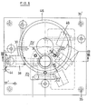
- a profiling apparatus comprises a tool-carrying carriage 1 on which is mounted a dressing head designated as a whole by the reference notation 2 with six stations with immediate indexing in both directions .
- the tool carriage 1 can move transversely to an unmounted work table of a grinding machine, along a slide 3 by driving with a ball screw 4 of the SKF VIS TRANSROL 12 x 2 type controlled by a pulley 5 and an electric motor 6.
- the threaded rod 4 is mounted on two NADELLA needle bearings 7 of type AX 4. 10. 12 ensuring assembly without play.
- the horizontal stroke of the tool carriage 1 is 75 millimeters, depending on the model.
- the horizontal movement control mechanism is designed for hand advance and automatic and micrometric advance to achieve high precision.
- the tool carriage 1 can also move in a vertical plane.
- the vertical stroke 67 millimeters long, takes place along a second slide 8 perpendicular to the first by driving with a threaded rod 9, similar to the first, controlled by a pulley 10 and an electric motor 6, possibly separate from the first.
- the horizontal and vertical strokes of the tool carriage 1 are fixed by microswitches.
- the slides 3 and 8 each consist of four guide rails 11.
- Two very high precision incremental closed linear measuring devices of the HEIDE-HAIN type designated as a whole by the reference numbers 12, 13 each include an incremental glass ruler 14, a sensing head or probe reticle not shown, a lamp not shown emitting a series of narrow light beams made up of photo-elements intended to capture said beams, and connected to a probe trolley.
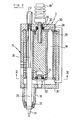
- the dressing head 2 consisting of a body or sheath 15 in which pivots a barrel 16 provided with a series of diamond tools 17 separate and retractable, for cutting, is mounted on the tool carriage 1 so that the pivot axis PP 'of said barrel 15 is substantially vertical.
- the above-mentioned cutting tools 17 are each slidably mounted in a cell 18 of said barrel 16.
- the barrel 16 carries an upper shaft 19 mounted on the sheath 15 using the upper bearing 20 and driven by the pulleys 19 '.
- the barrel also rests on the sheath 15 by means of the lower pivot 21 and the bearing 22.
- the barrel 16 comprises a series 23 of cells 18, for example six in number, of trapezoidal section and the walls of which have a groove 24 along which a slide 25 can be moved, actuated by a rod 26 and a jack 27.
- Each slide 25 carries a cutting tool 17.
- Each cutting tool 17 has a possibly distinct shape suitable for the profile to be produced.
- the cells 18 are delimited at their upper part by stop rings 28, 29.
- the sheath 15 is closed at its upper part and at its lower part by two covers 30 , fixed by screws 30 '.
- a guide 31, integral with the sheath 15 and mounted at the height of a recess 32 of this sheath 15, opposite the profiling station and a locking device 33 make it possible to rigidly fix each of the tools on the dressing head with sufficient rigidity .
- each of the tools 17 is obtained by repeated pivoting of the barrel 16 by an angle equal to that between two neighboring tools, in both directions.
- the barrel 16 can be rigidly locked in each of the positions so as to successively bring each of the tools 17 in front of the profiling or dressing station of the wheel not shown.
- the supply and the lifting of each of the tools 17 after their positioning opposite the dressing station by pivoting the barrel 16, is done pneumatically or hydraulically using a rod 26 driving the slide 25 enclosing the tool 17.
- This rod 26 brings each of the corresponding tools against a stop 34 judiciously studied guide 31 to ensure the locking of the tool 17 in the vicinity of the grinding wheel.
- This device makes it possible to reduce any overhang of each of the cutting tools with respect to the working surface of the grinding wheel to be profiled.
- the device described eliminates during the lifting of the tool 17 any risk of friction and shock of the tool 16 against any part of the profile of the grinding wheel not shown.
- the dressing head can be provided with a taring or positioning device made up of three micro-contact measurement units or strain gauges located in reference planes.
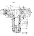
- FIGS. 6 and 7 A second embodiment of a locking and setting device is shown in FIGS. 6 and 7. It comprises a box 35 intended to allow the tool magazine according to the invention to be fixed and positioned, provided with a device locking and setting, generally designated by the reference notation 36, on any profiling machine using studs 35 '.
- the housing 35 comprises a centering ring 37 and a centering pin 37 'allowing the positioning of the housing.
- a piston rod 38 sliding transversely with respect to the axis of the guide 31 is held tightly in the cavity 39 by the piston seals 40 applied against the spacer ring 41 using the clamping ring 42 held in place by the screw 43.
- the cavity 39 is closed by the cover 44 and the O-ring 45.
- a ring 46 makes it possible to position the feelers 47 mounted on levers 48 which control the microswitch measurement units 49.
- the guide 31 consists of a tubular casing 50 provided at its end with a calibrated tip 51 intended to hold in place a clamping part 52 of the diamond tool intended to make up for any possible play.
- the clamping part 52 slides along a guide ring 53 and the tubular casing under the action of a control fluid supplied by inlet 54 and discharge 55 channels, the sealing of the hydraulic or pneumatic control being obtained by the O-rings 56, 57 and 58.
- the guide ring 53 also serves as an upper stop for the pinching rod 52.
- the calibrated nozzle 51 comprises two sealing rings 59, 60 as well as an annular recess 61 intended to distribute a powerful air blast intended for the scanning of possible impurities in the gantries of the calibrated nozzle 51.
- the tubular casing 50 has channels 6 2 intended for a cooling fluid.
- the apparatus described in this specification can be used to prepare an abrasive wheel. After the profiling operation, it is necessary to sharpen the working surface of the grinding wheel, i.e. to remove the binder superficially between the abrasive grains.
- One of the tools can then consist of a wheel or a appropriately shaped mild steel bar.
Landscapes
- Engineering & Computer Science (AREA)
- Mechanical Engineering (AREA)
- Grinding-Machine Dressing And Accessory Apparatuses (AREA)
- Finish Polishing, Edge Sharpening, And Grinding By Specific Grinding Devices (AREA)
Applications Claiming Priority (2)
| Application Number | Priority Date | Filing Date | Title |
|---|---|---|---|
| BE0/209730A BE895347A (fr) | 1982-12-14 | 1982-12-14 | Appareil a profiler une meule abrasive |
| BE209730 | 1982-12-14 |
Publications (2)
| Publication Number | Publication Date |
|---|---|
| EP0112320A2 true EP0112320A2 (de) | 1984-06-27 |
| EP0112320A3 EP0112320A3 (de) | 1985-11-27 |
Family
ID=3843583
Family Applications (1)
| Application Number | Title | Priority Date | Filing Date |
|---|---|---|---|
| EP83870127A Withdrawn EP0112320A3 (de) | 1982-12-14 | 1983-12-05 | Einrichtung zum Profilieren einer Schleifscheibe |
Country Status (6)
| Country | Link |
|---|---|
| US (1) | US4561415A (de) |
| EP (1) | EP0112320A3 (de) |
| JP (1) | JPS59118372A (de) |
| BE (1) | BE895347A (de) |
| CA (1) | CA1219449A (de) |
| ES (1) | ES527928A0 (de) |
Families Citing this family (7)
| Publication number | Priority date | Publication date | Assignee | Title |
|---|---|---|---|---|
| US5003730A (en) * | 1987-08-19 | 1991-04-02 | Bryant Grinder Corporation | Radius dressing apparatus |
| JPH0683941B2 (ja) * | 1988-04-15 | 1994-10-26 | 株式会社森精機製作所 | 工作機械の自動工具交換装置 |
| US5105528A (en) * | 1991-01-22 | 1992-04-21 | Universal Instruments Corporation | Method and apparatus for supplying and changing tips of a pick and place vacuum spindle |
| US5138799A (en) * | 1991-04-12 | 1992-08-18 | Bryant Grinder Corporation | Probe positioning mechanism for a radius dresser |
| US6949057B2 (en) * | 2003-09-02 | 2005-09-27 | The Boeing Company | Multi-function end effector |
| JP4469325B2 (ja) * | 2005-11-04 | 2010-05-26 | 株式会社森精機製作所 | 熱変位補正装置 |
| KR101136382B1 (ko) * | 2009-12-08 | 2012-04-18 | 한국기계연구원 | 형상기억합금을 이용한 공구 홀더 및 공구 고정방법 |
Family Cites Families (10)
| Publication number | Priority date | Publication date | Assignee | Title |
|---|---|---|---|---|
| US1461755A (en) * | 1923-07-17 | Automatic drill press | ||
| CH259526A (fr) * | 1948-01-05 | 1949-01-31 | Suter Arthur Robert | Machine-outil, à barillet porte-outils. |
| US2587172A (en) * | 1949-03-16 | 1952-02-26 | J K Smit & Sons Inc | Holder for diamond dressing tools |
| GB916294A (en) * | 1960-07-27 | 1963-01-23 | Jones & Shipman A A Ltd | Improvements relating to grinding wheels |
| DE1302431C2 (de) * | 1962-06-23 | 1975-05-07 | G. Bluthardt, Werkzeugmaschinenfabrik, 7440 Nürtingen | Bohr- und fraeseinheit mit werkzeugspeicher |
| US3413702A (en) * | 1965-03-01 | 1968-12-03 | Houdaille Industries Inc | Turret machine having tool store |
| DE1477779C3 (de) * | 1965-03-05 | 1974-10-17 | Stama Stark Maschinenfabrik Gotthilf Stark, 7311 Schlierbach | Revolverbohrmaschine |
| DD96430A1 (de) * | 1972-04-07 | 1973-03-20 | ||
| US3999769A (en) * | 1975-02-24 | 1976-12-28 | Bayer Jack L | Tool holder for machine tools |
| US4274231A (en) * | 1978-12-20 | 1981-06-23 | Boyar-Schultz Corporation | Method and apparatus for dressing a grinding wheel |
-
1982
- 1982-12-14 BE BE0/209730A patent/BE895347A/fr not_active IP Right Cessation
-
1983
- 1983-12-05 EP EP83870127A patent/EP0112320A3/de not_active Withdrawn
- 1983-12-07 US US06/559,113 patent/US4561415A/en not_active Expired - Fee Related
- 1983-12-09 ES ES527928A patent/ES527928A0/es active Granted
- 1983-12-13 CA CA000443164A patent/CA1219449A/fr not_active Expired
- 1983-12-13 JP JP58234920A patent/JPS59118372A/ja active Pending
Also Published As
| Publication number | Publication date |
|---|---|
| JPS59118372A (ja) | 1984-07-09 |
| ES8500114A1 (es) | 1984-11-01 |
| EP0112320A3 (de) | 1985-11-27 |
| CA1219449A (fr) | 1987-03-24 |
| ES527928A0 (es) | 1984-11-01 |
| US4561415A (en) | 1985-12-31 |
| BE895347A (fr) | 1983-06-14 |
Similar Documents
| Publication | Publication Date | Title |
|---|---|---|
| CN111618670A (zh) | 可调节的麻花钻修磨装置 | |
| CN110370169A (zh) | 夹紧机构、打磨装置及打磨方法 | |
| CN113510320A (zh) | 全自动数控螺纹磨床 | |
| EP0112320A2 (de) | Einrichtung zum Profilieren einer Schleifscheibe | |
| CN115351359A (zh) | 一种磨削螺旋锥齿轮的磨齿机床 | |
| US3680262A (en) | End mill grinder | |
| CN117086718B (zh) | 一种龙门式瓦楞辊磨床及其对刀方法 | |
| US2458472A (en) | Jaw grinding mechanism for car wheel boring mills | |
| TWM546285U (zh) | 立式磨床 | |
| CN112959145B (zh) | 车工刀具机械夹持修磨机 | |
| CN113560912A (zh) | 一种数控机床加工用夹具 | |
| CN211805414U (zh) | 一种用于磨床的多角度调节磨盘 | |
| Meyers et al. | Basic machining reference handbook | |
| US2404465A (en) | Radius to tangent compound angle dresser | |
| CN211760513U (zh) | 一种龙门磨床 | |
| JP7442999B2 (ja) | 研削ユニット、及びこれを備えた複合加工機械 | |
| US2398451A (en) | Dressing device for grinding wheels | |
| JP2021039058A (ja) | ねじ軸測定方法、並びにねじ軸測定装置及びこれを備えたnc工作機械 | |
| US3125932A (en) | Machine for the manufacture of metal cutting tools | |
| US4480410A (en) | Precision center lapping apparatus and method | |
| US2773333A (en) | Machine tool, especially grinding machines for machining rotating work pieces | |
| JP7446745B2 (ja) | ねじ軸の加工方法 | |
| US1497951A (en) | Portable power lathe and grinding machine | |
| KR200373282Y1 (ko) | 가공물의 표면 연마장치 | |
| CN113829202A (zh) | 打磨装置 |
Legal Events
| Date | Code | Title | Description |
|---|---|---|---|
| PUAI | Public reference made under article 153(3) epc to a published international application that has entered the european phase |
Free format text: ORIGINAL CODE: 0009012 |
|
| AK | Designated contracting states |
Designated state(s): AT CH DE FR GB IT LI LU NL SE |
|
| PUAL | Search report despatched |
Free format text: ORIGINAL CODE: 0009013 |
|
| RHK1 | Main classification (correction) |
Ipc: B24B 53/00 |
|
| AK | Designated contracting states |
Designated state(s): AT CH DE FR GB IT LI LU NL SE |
|
| 17P | Request for examination filed |
Effective date: 19860515 |
|
| 17Q | First examination report despatched |
Effective date: 19861028 |
|
| STAA | Information on the status of an ep patent application or granted ep patent |
Free format text: STATUS: THE APPLICATION IS DEEMED TO BE WITHDRAWN |
|
| 18D | Application deemed to be withdrawn |
Effective date: 19871229 |
|
| RIN1 | Information on inventor provided before grant (corrected) |
Inventor name: WILLOT, HENRI |