EP0112474A2 - Contrôle de la température d'une tête d'impression thermique - Google Patents
Contrôle de la température d'une tête d'impression thermique Download PDFInfo
- Publication number
- EP0112474A2 EP0112474A2 EP83111138A EP83111138A EP0112474A2 EP 0112474 A2 EP0112474 A2 EP 0112474A2 EP 83111138 A EP83111138 A EP 83111138A EP 83111138 A EP83111138 A EP 83111138A EP 0112474 A2 EP0112474 A2 EP 0112474A2
- Authority
- EP
- European Patent Office
- Prior art keywords
- bar
- thermal print
- print head
- temperature
- sensor
- Prior art date
- Legal status (The legal status is an assumption and is not a legal conclusion. Google has not performed a legal analysis and makes no representation as to the accuracy of the status listed.)
- Ceased
Links
Images
Classifications
-
- B—PERFORMING OPERATIONS; TRANSPORTING
- B41—PRINTING; LINING MACHINES; TYPEWRITERS; STAMPS
- B41J—TYPEWRITERS; SELECTIVE PRINTING MECHANISMS, i.e. MECHANISMS PRINTING OTHERWISE THAN FROM A FORME; CORRECTION OF TYPOGRAPHICAL ERRORS
- B41J2/00—Typewriters or selective printing mechanisms characterised by the printing or marking process for which they are designed
- B41J2/315—Typewriters or selective printing mechanisms characterised by the printing or marking process for which they are designed characterised by selective application of heat to a heat sensitive printing or impression-transfer material
- B41J2/32—Typewriters or selective printing mechanisms characterised by the printing or marking process for which they are designed characterised by selective application of heat to a heat sensitive printing or impression-transfer material using thermal heads
- B41J2/35—Typewriters or selective printing mechanisms characterised by the printing or marking process for which they are designed characterised by selective application of heat to a heat sensitive printing or impression-transfer material using thermal heads providing current or voltage to the thermal head
- B41J2/355—Control circuits for heating-element selection
- B41J2/36—Print density control
- B41J2/365—Print density control by compensation for variation in temperature
-
- B—PERFORMING OPERATIONS; TRANSPORTING
- B41—PRINTING; LINING MACHINES; TYPEWRITERS; STAMPS
- B41J—TYPEWRITERS; SELECTIVE PRINTING MECHANISMS, i.e. MECHANISMS PRINTING OTHERWISE THAN FROM A FORME; CORRECTION OF TYPOGRAPHICAL ERRORS
- B41J2/00—Typewriters or selective printing mechanisms characterised by the printing or marking process for which they are designed
- B41J2/315—Typewriters or selective printing mechanisms characterised by the printing or marking process for which they are designed characterised by selective application of heat to a heat sensitive printing or impression-transfer material
- B41J2/32—Typewriters or selective printing mechanisms characterised by the printing or marking process for which they are designed characterised by selective application of heat to a heat sensitive printing or impression-transfer material using thermal heads
- B41J2/35—Typewriters or selective printing mechanisms characterised by the printing or marking process for which they are designed characterised by selective application of heat to a heat sensitive printing or impression-transfer material using thermal heads providing current or voltage to the thermal head
- B41J2/355—Control circuits for heating-element selection
-
- B—PERFORMING OPERATIONS; TRANSPORTING
- B41—PRINTING; LINING MACHINES; TYPEWRITERS; STAMPS
- B41J—TYPEWRITERS; SELECTIVE PRINTING MECHANISMS, i.e. MECHANISMS PRINTING OTHERWISE THAN FROM A FORME; CORRECTION OF TYPOGRAPHICAL ERRORS
- B41J2/00—Typewriters or selective printing mechanisms characterised by the printing or marking process for which they are designed
- B41J2/315—Typewriters or selective printing mechanisms characterised by the printing or marking process for which they are designed characterised by selective application of heat to a heat sensitive printing or impression-transfer material
- B41J2/32—Typewriters or selective printing mechanisms characterised by the printing or marking process for which they are designed characterised by selective application of heat to a heat sensitive printing or impression-transfer material using thermal heads
- B41J2/375—Protection arrangements against overheating
Definitions
- the present invention relates to the sensing and control of the temperature of a thermal print head.
- thermal printing devices have been shown in the prior art. Such devices include matrices of elements for character formation, rows of elements for line printing, movable heads which traverse a sheet for printing and fixed heads which extend across a sheet for printing thereon as the sheet moves therepast.
- the print elements In general, in thermal print heads, the print elements must be capable of producing a temperature greater than that required to mark a sheet, but less than that required to burn or deform the sheet. Variations in parameters such as ambient temperature, printhead temperature rise after sustained printing, and print element resistance all cause difficulties in maintaining the desired print temperature. One particular difficulty is the problem in preventing temperature rise in a few only of the print elements when, for example, a vertical line is printed on a sheet, or a solid block area is printed thereon.
- the present invention provides an arrangement for sensing the temperature of each of a full row of thermal print elements.
- the sensing is effective not only when the general ambient temperature about the row rises but also when the temperature of only a few of the elements rises above a required limit.
- a thermal print head having a row of thermal print elements, characterised by a temperature sensor comprising a sensor bar of temperature sensitive material positioned in parallel with and in heat transfer proximity to, the row of print elements.
- a thermal print head comprising a continuous bar of resistive material, electrical connections to the bar defining print elements therebetween characterised by a sensor bar of temperature sensitive material positioned in parallel with, and in heat transfer proximity to, the bar of resistive material.
- a temperature control system for a thermal print head having a row of thermal print elements, characterised by a temperature sensor bar positioned in parallel with, and in heat transfer proximity to, said row of thermal print heads and a control circuit coupled to the sensor bar and operative to control the energy of print drive pulses applied to the print elements in accordance with the temperature sensed by the sensor element.
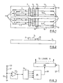
- Fig. 1 is a top view, partially broken away, of a thermal print head.
- This head comprises a substrate 1 supporting a pair of print bars 2, 3 of resistive material.
- a plurality of connector pads 4 are connected to lines 5 which extend under, and connect to, bar 3.
- Further connector pads 6 are similarly connected to bar 2 through lines 7.
- Yet another set of connector pads 8 are connected, through lines 9, first to bar 2 and then to bar 3.
- the lead connections to the bars define print elements therebetween. These elements are energised in a sequence of four stages. In the first stage, selected ones of leads 9 are driven and a ground return is completed for the lowest one of leads 5 and alternate ones of these leads. In the second stage, selected leads 9 are driven and the remaining leads 5 are ground returned.
- a single line of dots is formed on a sheet passing across the bars from right to left in Fig. 1.
- the bars are of a length to extend fully across the width of such a sheet.
- the sheet may be of thermally sensitive material, in which case it contacts the bars.
- a sheet carrying heat-transferable ink may be sandwiched between a plain paper sheet and the bars to effect printing on the plain sheet.
- a sensor bar of thermo-resistive material 10 is positioned parallel, and in close proximity to print bar 3.
- Sensor bar 10 is insulated from leads 5 by a layer of insulant 11 for example, glass.
- Fig. 2 shows the arrangement of the print and sensor bars. This figure has been simplified by omitting the leads and connector pads.
- the bars 2 and 3 extend further from the substrate 1 than the insulant/sensor bar combination to avoid the sensor bar contacting a sheet in contact with the print bars.
- the sensor bar is heated by radiation from bar 3. In practice, this radiation is concentrated on to the sensor bar by a sheet in contact with bar 3.
- connector pads 12 and 13 are connected to respective ends of sensor bar 10 by means of leads 14 and 15.
- Figs. 1 and 2 are highly magnified views of the print head.
- the substrate 1 is a slice of silicon material with the leads and pads screened thereon.
- the glass layer 10 is formed over leads 5 and leads 14 and 15 are screened on to the substrate and over layer 10.
- the bars are then screened over the leads for connection thereto.
- Bar 10 may be formed from a paste of thermo-resisitve material with a negative temperature coefficient, which, after laying down, is hardened. Typical dimensions are, length of bars, 200 mm, and 0.19 mm spacing between longitudinal center lines of the bars.
- Fig. 3 is a simplified block diagram of a temperature control circuit for the Fig. 1 print head.
- the sensor bar 10 is connected in series with a resistor 21 between a terminal 22 coupled to a voltage reference source and earth.
- the voltage developed across sensor bar 10, which varies in accordance with the temperture of the bar is fed to operational amplifier 23, which acts as an isolating amplifier.
- the output from amplifier 23 is applied to an anlog-to-digital converter 24, to provide digital outputs representative of the sensor bar temperature.
- a controller which may, for example, be a micro-processor.
- the resultant output from the micro-processor on line 28 controls a shift-register/drive circuit 26, which applies the drive pulses to leads 9 (Fig.
- controller 25 may act to change the output 28 only upon the detection of temperature values beyond predetermined limits of a given temperature band.
- thermo-resistive type it may alternatively be formed from thermo-voltaic material.
Landscapes
- Electronic Switches (AREA)
- Facsimile Heads (AREA)
Applications Claiming Priority (2)
| Application Number | Priority Date | Filing Date | Title |
|---|---|---|---|
| US06/452,989 US4449033A (en) | 1982-12-27 | 1982-12-27 | Thermal print head temperature sensing and control |
| US452989 | 1982-12-27 |
Publications (2)
| Publication Number | Publication Date |
|---|---|
| EP0112474A2 true EP0112474A2 (fr) | 1984-07-04 |
| EP0112474A3 EP0112474A3 (fr) | 1986-03-12 |
Family
ID=23798776
Family Applications (1)
| Application Number | Title | Priority Date | Filing Date |
|---|---|---|---|
| EP83111138A Ceased EP0112474A3 (fr) | 1982-12-27 | 1983-11-08 | Contrôle de la température d'une tête d'impression thermique |
Country Status (3)
| Country | Link |
|---|---|
| US (1) | US4449033A (fr) |
| EP (1) | EP0112474A3 (fr) |
| JP (1) | JPS59120476A (fr) |
Cited By (5)
| Publication number | Priority date | Publication date | Assignee | Title |
|---|---|---|---|---|
| AU568254B2 (en) * | 1985-10-08 | 1987-12-17 | Sato, K.K. | Preventing overheating of thermal printer |
| GB2204280A (en) * | 1987-04-27 | 1988-11-09 | Canon Kk | Thermal head and thermal recording apparatus using the same |
| WO1989002367A1 (fr) * | 1987-09-08 | 1989-03-23 | Siemens Aktiengesellschaft | Installation d'impression a tete d'impression comandee electrothermiquement |
| US4887092A (en) * | 1987-12-07 | 1989-12-12 | Siemens Aktiengesellschaft | Thermal printing method |
| EP0420412A1 (fr) * | 1989-08-25 | 1991-04-03 | Sharp Kabushiki Kaisha | Tête thermique |
Families Citing this family (11)
| Publication number | Priority date | Publication date | Assignee | Title |
|---|---|---|---|---|
| JPS58138665A (ja) * | 1982-02-12 | 1983-08-17 | Fuji Xerox Co Ltd | 感熱記録ヘツド駆動装置 |
| JPS58220757A (ja) * | 1982-06-18 | 1983-12-22 | Canon Inc | 液体噴射記録装置 |
| US4797837A (en) * | 1986-04-24 | 1989-01-10 | Ncr Canada Ltd. - Ncr Canada Ltee | Method and apparatus for thermal printer temperature control |
| US4758966A (en) * | 1986-05-05 | 1988-07-19 | Ncr Canada Ltd. - Ncr Canada Ltee | Thermal printing apparatus and method |
| JP2831778B2 (ja) * | 1989-02-03 | 1998-12-02 | キヤノン株式会社 | 液体噴射記録ヘッド、該記録ヘッド用基板および記録装置 |
| US5075690A (en) * | 1989-12-18 | 1991-12-24 | Xerox Corporation | Temperature sensor for an ink jet printhead |
| US5166699A (en) * | 1990-04-11 | 1992-11-24 | Canon Kabushiki Kaisha | Recording apparatus |
| FR2662395A1 (fr) * | 1990-05-23 | 1991-11-29 | Axiohm | Perfectionnement aux tetes thermiques d'imprimantes. |
| JP4177601B2 (ja) * | 2002-06-05 | 2008-11-05 | セイコーインスツル株式会社 | 感熱性粘着シートの熱活性化装置およびプリンタ装置 |
| US6902256B2 (en) | 2003-07-16 | 2005-06-07 | Lexmark International, Inc. | Ink jet printheads |
| EP1730023A4 (fr) * | 2004-03-11 | 2007-11-07 | Benmaxx Llc | Tambour de frein leger renforce et procede de realisation |
Family Cites Families (21)
| Publication number | Priority date | Publication date | Assignee | Title |
|---|---|---|---|---|
| US3453647A (en) * | 1965-03-24 | 1969-07-01 | American Standard Inc | Thermographic recording apparatus |
| US3577137A (en) * | 1968-12-31 | 1971-05-04 | Texas Instruments Inc | Temperature compensated electronic display |
| US4039065A (en) * | 1972-08-15 | 1977-08-02 | Canon Kabushiki Kaisha | Thermal printer |
| US3874493A (en) * | 1972-11-06 | 1975-04-01 | Texas Instruments Inc | Electronic page printer |
| US3813513A (en) * | 1973-03-16 | 1974-05-28 | Ibm | Thermal printing device |
| US3953708A (en) * | 1975-04-25 | 1976-04-27 | Xerox Corporation | Thermal printer using amorphous semiconductor devices |
| SE431805B (sv) * | 1976-04-05 | 1984-02-27 | Oki Electric Ind Co Ltd | Termiskt skrivarhuvud |
| JPS5393843A (en) * | 1977-01-28 | 1978-08-17 | Hitachi Ltd | Thermographic head |
| JPS53116847A (en) * | 1977-03-23 | 1978-10-12 | Toshiba Corp | Heat-sensitive printing apparatus |
| US4099046A (en) * | 1977-04-11 | 1978-07-04 | Northern Telecom Limited | Thermal printing device |
| JPS5497438A (en) * | 1978-01-18 | 1979-08-01 | Hitachi Ltd | Heat sensitive recording device |
| JPS54141650A (en) * | 1978-04-27 | 1979-11-05 | Oki Electric Ind Co Ltd | Printer |
| JPS5953875B2 (ja) * | 1978-06-14 | 1984-12-27 | 株式会社東芝 | 感熱記録ヘツド |
| JPS5539333A (en) * | 1978-09-13 | 1980-03-19 | Canon Inc | Thermographic apparatus |
| US4232212A (en) * | 1978-10-03 | 1980-11-04 | Northern Telecom Limited | Thermal printers |
| JPS5551574A (en) * | 1978-10-06 | 1980-04-15 | Canon Inc | Thermal transfer recorder |
| US4242565A (en) * | 1979-06-05 | 1980-12-30 | Minnesota Mining And Manufacturing Company | Thermal print head |
| US4271414A (en) * | 1979-09-04 | 1981-06-02 | Gould Inc. | Thermal array protection apparatus |
| US4246587A (en) * | 1979-09-04 | 1981-01-20 | Gould Inc. | Thermal array protection method and apparatus |
| JPS5757679A (en) * | 1980-09-24 | 1982-04-06 | Canon Inc | Device for driving thermal head |
| JPS57205173A (en) * | 1981-06-12 | 1982-12-16 | Hitachi Ltd | Temperature detector for heat sensitive head |
-
1982
- 1982-12-27 US US06/452,989 patent/US4449033A/en not_active Expired - Lifetime
-
1983
- 1983-10-11 JP JP58188590A patent/JPS59120476A/ja active Pending
- 1983-11-08 EP EP83111138A patent/EP0112474A3/fr not_active Ceased
Cited By (9)
| Publication number | Priority date | Publication date | Assignee | Title |
|---|---|---|---|---|
| AU568254B2 (en) * | 1985-10-08 | 1987-12-17 | Sato, K.K. | Preventing overheating of thermal printer |
| GB2204280A (en) * | 1987-04-27 | 1988-11-09 | Canon Kk | Thermal head and thermal recording apparatus using the same |
| US4947188A (en) * | 1987-04-27 | 1990-08-07 | Canon Kabushiki Kaisha | Thermal head and thermal recording apparatus using the same |
| GB2204280B (en) * | 1987-04-27 | 1991-11-06 | Canon Kk | Thermal head and thermal recording apparatus using the same |
| WO1989002367A1 (fr) * | 1987-09-08 | 1989-03-23 | Siemens Aktiengesellschaft | Installation d'impression a tete d'impression comandee electrothermiquement |
| US5122816A (en) * | 1987-09-08 | 1992-06-16 | Siemens Aktiengesellschaft | Printer means having an electrothermally operated printing head |
| US4887092A (en) * | 1987-12-07 | 1989-12-12 | Siemens Aktiengesellschaft | Thermal printing method |
| EP0420412A1 (fr) * | 1989-08-25 | 1991-04-03 | Sharp Kabushiki Kaisha | Tête thermique |
| US5121135A (en) * | 1989-08-25 | 1992-06-09 | Sharp Kabushiki Kaisha | Thermal head having integral analog drive compensation |
Also Published As
| Publication number | Publication date |
|---|---|
| US4449033A (en) | 1984-05-15 |
| EP0112474A3 (fr) | 1986-03-12 |
| JPS59120476A (ja) | 1984-07-12 |
Similar Documents
| Publication | Publication Date | Title |
|---|---|---|
| US4449033A (en) | Thermal print head temperature sensing and control | |
| US5610650A (en) | Electronic parts, thermal head, manufacturing method of the thermal head, and heat sensitive recording apparatus | |
| US4636812A (en) | Thermal print head temperature control | |
| KR0167406B1 (ko) | 서멀 헤드 장치 | |
| US4539571A (en) | Thermal printing system | |
| US3961155A (en) | Thermal printing element arrays | |
| EP0077546B1 (fr) | Appareil d'enregistrement thermique | |
| EP0186059B1 (fr) | Tête d'impression thermique | |
| US4450342A (en) | Thermal print head | |
| JP2929649B2 (ja) | サーマルヘッドおよびその製造方法 | |
| JP3333264B2 (ja) | ヒータ素子およびその製造方法 | |
| US4217480A (en) | Thermal print bar | |
| EP0415718A1 (fr) | Tête thermique | |
| JP2562880B2 (ja) | サ−マルヘツド | |
| JP2554556B2 (ja) | サ−マルプリントヘッド | |
| US8243112B2 (en) | Recording head and recording apparatus provided with the recording head | |
| JP3592440B2 (ja) | サーマルプリントヘッド | |
| JPH08150750A (ja) | サーマルヘッド | |
| JPH0751362B2 (ja) | サーマルヘツド | |
| CA1098581A (fr) | Barrette d'impression par voie thermique | |
| KR0151098B1 (ko) | 분할 발열부형 감열기록소자 | |
| KR930006830B1 (ko) | 고저항 감열기록 소자 | |
| JPH1071736A (ja) | サーマルヘッド | |
| JP3114057B2 (ja) | サーマルスタンプヘッド | |
| JPS5839073B2 (ja) | ドツトプリンタノセイギヨホウホウ |
Legal Events
| Date | Code | Title | Description |
|---|---|---|---|
| PUAI | Public reference made under article 153(3) epc to a published international application that has entered the european phase |
Free format text: ORIGINAL CODE: 0009012 |
|
| AK | Designated contracting states |
Designated state(s): DE FR GB |
|
| 17P | Request for examination filed |
Effective date: 19841029 |
|
| PUAL | Search report despatched |
Free format text: ORIGINAL CODE: 0009013 |
|
| AK | Designated contracting states |
Kind code of ref document: A3 Designated state(s): DE FR GB |
|
| 17Q | First examination report despatched |
Effective date: 19870624 |
|
| STAA | Information on the status of an ep patent application or granted ep patent |
Free format text: STATUS: THE APPLICATION HAS BEEN REFUSED |
|
| 18R | Application refused |
Effective date: 19880707 |
|
| RIN1 | Information on inventor provided before grant (corrected) |
Inventor name: RAKES, JAMES MITCHELL Inventor name: MCCLURE, RICHARD GERARD Inventor name: WILLIAMS, ERROL RAY |