EP0112535A1 - Verfahren und Vorrichtung zur Brennstoffzuführung für Kohlenstaubbrenner - Google Patents
Verfahren und Vorrichtung zur Brennstoffzuführung für Kohlenstaubbrenner Download PDFInfo
- Publication number
- EP0112535A1 EP0112535A1 EP83112536A EP83112536A EP0112535A1 EP 0112535 A1 EP0112535 A1 EP 0112535A1 EP 83112536 A EP83112536 A EP 83112536A EP 83112536 A EP83112536 A EP 83112536A EP 0112535 A1 EP0112535 A1 EP 0112535A1
- Authority
- EP
- European Patent Office
- Prior art keywords
- coal
- air
- fuel
- swirling
- fuel jet
- Prior art date
- Legal status (The legal status is an assumption and is not a legal conclusion. Google has not performed a legal analysis and makes no representation as to the accuracy of the status listed.)
- Granted
Links
Images




Classifications
-
- F—MECHANICAL ENGINEERING; LIGHTING; HEATING; WEAPONS; BLASTING
- F23—COMBUSTION APPARATUS; COMBUSTION PROCESSES
- F23D—BURNERS
- F23D1/00—Burners for combustion of pulverulent fuel
-
- F—MECHANICAL ENGINEERING; LIGHTING; HEATING; WEAPONS; BLASTING
- F23—COMBUSTION APPARATUS; COMBUSTION PROCESSES
- F23C—METHODS OR APPARATUS FOR COMBUSTION USING FLUID FUEL OR SOLID FUEL SUSPENDED IN A CARRIER GAS OR AIR
- F23C6/00—Combustion apparatus characterised by the combination of two or more combustion chambers or combustion zones, e.g. for staged combustion
- F23C6/04—Combustion apparatus characterised by the combination of two or more combustion chambers or combustion zones, e.g. for staged combustion in series connection
- F23C6/045—Combustion apparatus characterised by the combination of two or more combustion chambers or combustion zones, e.g. for staged combustion in series connection with staged combustion in a single enclosure
- F23C6/047—Combustion apparatus characterised by the combination of two or more combustion chambers or combustion zones, e.g. for staged combustion in series connection with staged combustion in a single enclosure with fuel supply in stages
-
- F—MECHANICAL ENGINEERING; LIGHTING; HEATING; WEAPONS; BLASTING
- F23—COMBUSTION APPARATUS; COMBUSTION PROCESSES
- F23D—BURNERS
- F23D1/00—Burners for combustion of pulverulent fuel
- F23D1/02—Vortex burners, e.g. for cyclone-type combustion apparatus
-
- F—MECHANICAL ENGINEERING; LIGHTING; HEATING; WEAPONS; BLASTING
- F23—COMBUSTION APPARATUS; COMBUSTION PROCESSES
- F23C—METHODS OR APPARATUS FOR COMBUSTION USING FLUID FUEL OR SOLID FUEL SUSPENDED IN A CARRIER GAS OR AIR
- F23C2201/00—Staged combustion
- F23C2201/20—Burner staging
-
- F—MECHANICAL ENGINEERING; LIGHTING; HEATING; WEAPONS; BLASTING
- F23—COMBUSTION APPARATUS; COMBUSTION PROCESSES
- F23C—METHODS OR APPARATUS FOR COMBUSTION USING FLUID FUEL OR SOLID FUEL SUSPENDED IN A CARRIER GAS OR AIR
- F23C2201/00—Staged combustion
- F23C2201/30—Staged fuel supply
-
- F—MECHANICAL ENGINEERING; LIGHTING; HEATING; WEAPONS; BLASTING
- F23—COMBUSTION APPARATUS; COMBUSTION PROCESSES
- F23C—METHODS OR APPARATUS FOR COMBUSTION USING FLUID FUEL OR SOLID FUEL SUSPENDED IN A CARRIER GAS OR AIR
- F23C2201/00—Staged combustion
- F23C2201/30—Staged fuel supply
- F23C2201/301—Staged fuel supply with different fuels in stages
Definitions
- the present invention relates to a fuel burner for coal in the fine powder form (hereinafter referred to as the pulverized coal) used for boilers.
- Fossile fuels contain the nitrogen (N) component besides the fuel components such as carbon and hydrogen.
- the N content is great in comparison with gas fuels and liquid fuels.
- NO nitrogen oxides
- Conventional combustion method to restrict the formation of NO x includes a two-stage combustion method which arranges the primary fuel nozzle jetting the first fuel with a smaller air ratio at the inner cylindrical portion and the second fuel nozzle jetting the second fuel with a large air ratio at the outer cylindrical portion which is located at the outer circumferential portion of the inner cylindrical portion.
- An object of the present invention is to provide method and apparatus which is suitable for reducing NO generated at combustion of the pulverized coal.
- the fuel jet method for a low NO x burner in accordance with the present invention is characterized in that the first coal in the fine powder form with an air ratio up to 1 is jetted from the inner cylindrical portion, and the second coal in the fine powder form with an air ratio of at least 1 is jetted and swirled from the outer cylindrical portion.
- the fuel jet apparatus for a low NO x burner in accordance with the present invention is characterized in that the apparatus comprises the primary fuel nozzle for jetting the first coal in the fine powder form by means of air at the inner cylindrical portion, the secondary fuel nozzle for jetting the second coal in the fine powder form disposed around the outer cylindrical portion which is located at the outer circumferential portion of the inner cylindrical portion, and swirl means for swirling the second coal at the point of the secondary fuel nozzle.
- the combustible components in the coal can be broadly classified into a volatile component and a solid component.
- the combustion mechanism of the pulverized coal consists of a pyrolytic process where the volatile component is emitted and a combustion process where the combustible solid component (hereinafter referred to as the "char.") is burnt after the pyrolysis.
- the combustion speed of the volatile component is higher than that of the solid component and the volatile component is burnt at the initial stage of combustion.
- the N content contained in the coal is also divided into the part which is emitted upon evaporation and the part which remains in the char, in the same way as other combustible components. Accordingly, fuel NO generated at the time of combustion of the pulverized coal is divided into NO from the volatile N content and NO from the N content in the char. x
- the volatile N changes to compounds such as NH 3 and HCN at the initial stage of combustion and in the combustion range in which oxygen is lean. These nitrogen compounds partly react with oxygen to form NO x and partly react with the resulting NO to form a reducing agent which decomposes NO to nitrogen.
- This NO x reducing reaction due to the nitrogen compounds proceeds in a system in which NO x is co-present. In a reaction system where NO x does not exist, however, most of the nitrogen compounds are oxidized to NO. This reducing reaction proceeds more easily in a lower oxygen concentration atmosphere.
- the formation quantity of NO x from the char is smaller than NO x from the volatile component, but in accordance with the conventional two-stage combustion method, it is not possible to restrict NO x from the char.
- NO x from the char In order to restrict NO x from the char, it is effective to emit once the N component in the char as the gas and to reduce the substances emitted this time as NO x to nitrogen using a reducing substance.
- To emit the N component in the char as the gas it is necessary to completely burn the char and hence, the formation of complete combustion range is indispensable as the low NO x combustion method of the pulverized coal.
- an effective combustion method which reduces NO x at the time of combustion of the pulverized coal will be one that permits the co-presence of the char, NO x and reducing nitrogen compounds so as to reduce NO x to nitrogen by the reducing nitrogen compounds.
- it is an effective combustion method which utilizes the nitrogen compounds as the precursor of NO x for reducing NO x to nitrogen and thus extinguishes the resulting NO x as well as the NO x precursor.
- the method of our present invention comprises the step of carrying out combustion bringing the second pulverized coal from the secondary fuel nozzle to the level of an air ratio of at least 1, the step of forming the reduction region of an air ratio of up to 1 by' feeding the first pulverized coal from the primary fuel nozzle so as to reduce the resulting NO x , and the step of swirling the second pulverized coal for preventing the second pulverized coal from being mixed immediately into the region where the thermal resolution of the primary pulverized coal occurs.
- each combustion region formed by the first and second coals or the primary and secondary fuel nozzles being divided clearly, the present invention can reduce NO generated at the combustion of the pulverized coal.
- reference numeral 11 designates a primary fuel nozzle for jetting pulverized coal and a secondary fuel nozzle 13 for jetting likewise the pulverized coal is disposed concentrically with the primary fuel nozzle around the outer circumference of the former.
- the secondary fuel nozzle 13 has a swirl flow generator 15 of an axial flow type which is coated with ceramic and swirls and jets the pulverized coal.
- Reference numeral 14 represents air nozzles disposed around the outer circumference of the secondary fuel nozzles. In this embodiment, eight air nozzles are disposed equidistantly around the secondary fuel nozzle 13. The angle of inclination of the swirl flow generator 15 and air nozzles 14 is within the range of 45° to 90° along the axis of the burner 10.
- Reference numeral 16 represents a cylindrical boiler preheating fuel jet nozzle disposed at the center of the primary fuel nozzle 11. At the time of preheating of a combustion furnace at the start, it jets the gas fuel for combustion. The air is used for transporting the pulverized coal and the primary and secondary fuel nozzles 11 and 13 jet the pulverized coal as such. The swirling speed of the air jetted from the air nozzles is higher than that of the pulverized coal jetted from the secondary fuel nozzle 13. These members 11 through 16 constitute the burner 10 of the present invention.
- Fig. 3 illustrates an example of a pulverized coal combustion apparatus using the burner 10 of the present invention.
- a plurality of burners 10a, 10b, 10c of the invention are disposed in the direction of height of a boiler 20.
- Reference numeral 21 represents a pulverizer which pulverizes the coal 22 as the fuel. In the case of ordinary combustion, it pulverizes the coal so that coal having a particle size of up to 74 ⁇ m accounts for about 80 %. :
- Reference numeral 23 represents a separator which separates the pulverized coal in accordance with the particle size.
- This separator 23 may be a cyclon separator or a louver separator.
- Reference numeral 24 represents an ejector disposed below the separator 23 and supplying the coarse coal separated by the separator 23 to the secondary fuel nozzles of the burners 10a, 10b, 10c from a tube 25 by the air.
- the fine coal separated by the separator 23 is also supplied from a tube 26 to the primary fuel nozzles of the burners 10a, 10b, 10c by means of the air in the same way.
- Reference numeral 27 represents a tube for feeding the air to the air nozzles of the burners 10a, 10b, 10c and this tube 27 branches from a main tube 28.
- Reference numeral 29 represents a tube which also braches from the main tube 28 and has its other end connected to the ejector 24.
- the gas fuel is jetted from the boiler preheating jet nozzle 16 for combustion at the start of operation of the boiler 20. After the temperature inside the boiler 20 reaches a predetermined temperature, the jet of the gas fuel is stopped and the pulverized coal is jetted from the primary and secondary nozzles 11, 13 of each burner 10a, 10b, 10c. Then, the combustion is effected.
- FIG. 4 shows the relation between the secondary fuel ratio, the amount of secondary fuel-f 2 per the amount of the primary fuel f i plus the amount of the secondary fuel f 2 , and NO , when the air nozzle 14 shown in FIGs. 1 and 2 are removed.
- 41 shows the characteristic curve when the swirl flow generator 15 is not used and the speed V 1 of the first fuel jetted from the primary fuel nozzle 11 is 23 m/sec
- 42 represents the characteristic curve when the angle of the inclination of the swirl 15 is 60° along the axis of the burner 10 and the speed V I of the first fuel is 23 m/sec as well as in the characteristic curve 41.
- the coal used is Taiheiyo Coal of Japan, which is pulverized into a particle size such that about 80 % passes through a 200-mesh sieve.
- the feed quantity of the pulverized coal is 30 kg/h and the furnace has an inner diameter of 700 mm and a length of 2 m.
- the feed quantity of the pulverized coal from each fuel nozzle 11, 13 is at an equall rate of 15 kg/h. That is, this is the ratio obtained under the experimental condition where the ratio of the air quantity jetted from the primary fuel nozzle 11 and the minimum air quantity necessary for completely burning the pulverized coal jetted from the primary fuel nozzle 11 is set to 0.2.
- NO generated in the furnace can be reduced about 100 ppm compared to when the swirl flow generator being not used.
- 51 represents the characteristic curve when the air nozzle 14 is not used, the speed V 1 is 25 m/sec, and f 2/ (f 1 +f 2 ) is 0.25.
- the swirl number is profitable to be approximately 0.75 to 1.3.
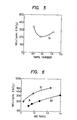
- FIG. 6 illustrates the generation quantity of NO x when the pulverized coals are burnt and the air is supplied from air nozzles 14 using the burner shown in FIGs. 1 and 2.
- the abscissa of FIG. 6 represents an air ratio which is the quotient of the sum of the air quantities jetted from the nozzles 11, 13, 14 by the minimum air quantity necessary for completely burning the pulverized coal jetted from each of the primary and secondary fuel nozzles 11, 13.
- the ordinate represents the NO x concentration in the combustion exhaust gas.
- 61 represents the characteristic curve when the air nozzles 14 have no swirl angle as shown in FIGs.1 and 2, and the swirl number at the air nozzle 14 is zero.
- 62 represents the characteristic curve when the swirl angle of the air nozzles 14 or the third air nozzles is formed 90° and the swirl number at the nozzles is 1.08.
- the velocity V 1 is 23 m/sec
- the swirl angle of the swirl means 15 is formed 60°
- the secondary fuel ratio-f 2 /(f 1 +f 2 ) is 0.2.
- the amount of NO x can be reduced approximately 170 ppm at the same air ratio.
- FIG. 7 illustrates an example where the feed quantity of the pulverized coal from each fuel nozzle 11, 13 is at an equal level of 15 kg/h, but the overall air ratio X is kept at a constant level of about 1.3 and the air ratio ⁇ 1 of the internal flame formed by the fuel and air jetted from the primary fuel nozzle 11 is changed (hereinafter, this ratio will be referred to as the "primary air ratio").
- the air quantity from the air nozzle 14 is changed in accordance with the change of the primary air ratio ⁇ 1 .
- the abscissa in FIG. 7 represents the primary air ratio ⁇ 1 and the ordinate does the NO concentration in the combustion exhaust gas. It can be understood from the curve 71 that an optimal value exists for the primary air ratio ⁇ 1 and a primary air ratio ⁇ 1 , at which NO becomes minimal, also exists.
- the primary air ratio ⁇ 1 at which NO becomes minimal is a value below 1 and becomes substan- x tially minimal at about 0.1 to 0.3.
- the result means that NO x can be reduced effectively by keeping the interrnal flame formed by the fuel jetted from the primary fuel nozzle 11 in the reducing atmosphere while keeping the external flame formed by the fuel jetted from the secondary fuel nozzle 13 within the complete combustion range of the air ratio of more than 1 and more particularly, at least 2.
- FIGs.8 through 10 illustrate the formation of NO x , unburnt components in the combustion ash and the formation characteristics of thermal NO x formed upon oxidation of the N content in the coal when the air for combustion and the fuel coal are mixed in advance and this mixed gas flow is supplied into a heating furnace at 1,600°C, respectively.
- the coal used is T aiheiyo Coal of Japan, and the heating furnace has an inner diameter of 50 mm and a heating portion of 800 mm long.
- the combustion air flow rate is 20 Nl/min and the air ratio is adjusted by changing the feed coal quantity.
- the fuel NO x is obtained from the difference between NO x formed when combustion is made using the air and NO x formed when argon-oxygen synthetic gas is used for combustion.
- Curves 81, 91, 101, 111 in FIGs. 8 through 11 represents the results when fine pulverized coal having a particle size of up to 74 ⁇ m is burnt while curves 82, 92, 102, 112 represent the results when coarse pulverized coal having a particle size of more than 105 ⁇ m is burnt. It can be seen that when comparison is made at the same air ratio shown in FIG. 8, the quantity of the whole NO (sum of fuel NO and thermal NO ) is greater in the case of the combustion of fine pulverized coal than in the case of the combustion of coarse pulverized coal.
- FIG. 8 shows that when comparison is made at the same air ratio shown in FIG. 8, the quantity of the whole NO (sum of fuel NO and thermal NO ) is greater in the case of the combustion of fine pulverized coal than in the case of the combustion of coarse pulverized coal.
- FIG. 10 illustrates the relation of the fuel NO formed x as a result of oxidation of the N component in the coal and the air ratio. It can be seen from the comparison of the curve 101 with 102 that the generation quantity of the fuel NO is greater in the case of the fine pulverized coal than in the case of the coarse pulverized coal. Further, FIG.11 shows the relation between the thermal NO and the air ratio. x In the same way as in FIG. 10, it can be understood that the thermal NO x is also greater for the fine pulverized coal than for the coarse pulverized coal.
- the present invention will be described in further detail using the burner shown in FIG. 1 on the basis of FIGs. 8 through 11.
- the fuel coal pulverized to the pulverized coal is separated into the fine coal and the coarse coal and the fine cial is used as the primary fuel and the coarse coal, as the secondary fuel. Since the coarse coal is used as the secondary fuel, the coarse coal which is apt to form a large quantity of unburnt components in the combustion ash, can be burnt at a high air ratio, whereby the increase of the unburnt components can be restricted.
- the NO x formation quantity is smaller for the coarse coal than for the fine coal, NO x can be reduced than when the fine coal is burnt at a high air ratio.
- the fine coal having a greater NO x generation quantity is used as the primary fuel and is burnt at a low air ratio so as to utilize it for forming an NO x reducing agent, the formation of NO x can be restricted.
- the internal flame burning at a low air ratio is encompassed therearound by the external flame of a high air ratio, the reaction in the internal flame is promoted by the heat of radiation from the external flame. Since the recycling flow is generated from the external flame to the internal flame in the region where the swirl flow applied to the external flame decays, mixing between the excessive oxygen in the external flame and the unburnt component generated in the internal flame is promoted and emission of the unburnt component can be restricted.
- the present invention maeks it possible to clearly divide the combustion flame of the pulverized coal into the NO x formation region and the reducing substance formation region for reducing NO x and can promote mixing of the reaction products from both regions. Accordingly, the present invention can reduce NO as well as emission of the unburnt x components.
Landscapes
- Engineering & Computer Science (AREA)
- Chemical & Material Sciences (AREA)
- Combustion & Propulsion (AREA)
- Mechanical Engineering (AREA)
- General Engineering & Computer Science (AREA)
Applications Claiming Priority (2)
| Application Number | Priority Date | Filing Date | Title |
|---|---|---|---|
| JP226907/82 | 1982-12-27 | ||
| JP57226907A JPS59119106A (ja) | 1982-12-27 | 1982-12-27 | 微粉炭燃焼バーナを備えたボイラ |
Publications (2)
| Publication Number | Publication Date |
|---|---|
| EP0112535A1 true EP0112535A1 (de) | 1984-07-04 |
| EP0112535B1 EP0112535B1 (de) | 1987-07-29 |
Family
ID=16852462
Family Applications (1)
| Application Number | Title | Priority Date | Filing Date |
|---|---|---|---|
| EP83112536A Expired EP0112535B1 (de) | 1982-12-27 | 1983-12-13 | Verfahren und Vorrichtung zur Brennstoffzuführung für Kohlenstaubbrenner |
Country Status (4)
| Country | Link |
|---|---|
| US (1) | US4515094A (de) |
| EP (1) | EP0112535B1 (de) |
| JP (1) | JPS59119106A (de) |
| DE (1) | DE3372814D1 (de) |
Cited By (1)
| Publication number | Priority date | Publication date | Assignee | Title |
|---|---|---|---|---|
| EP0303522A1 (de) * | 1987-08-13 | 1989-02-15 | The University Of Sydney | Brennstaubbrenner |
Families Citing this family (14)
| Publication number | Priority date | Publication date | Assignee | Title |
|---|---|---|---|---|
| US4596198A (en) * | 1983-05-18 | 1986-06-24 | Air Products And Chemicals, Inc. | Slag reduction in coal-fired furnaces using oxygen enrichment |
| US4627366A (en) * | 1985-09-16 | 1986-12-09 | The Babcock & Wilcox Company | Primary air exchange for a pulverized coal burner |
| US4899670A (en) * | 1988-12-09 | 1990-02-13 | Air Products And Chemicals, Inc. | Means for providing oxygen enrichment for slurry and liquid fuel burners |
| US5131334A (en) * | 1991-10-31 | 1992-07-21 | Monro Richard J | Flame stabilizer for solid fuel burner |
| US5365865A (en) * | 1991-10-31 | 1994-11-22 | Monro Richard J | Flame stabilizer for solid fuel burner |
| US5415114A (en) * | 1993-10-27 | 1995-05-16 | Rjc Corporation | Internal air and/or fuel staged controller |
| US6250915B1 (en) | 2000-03-29 | 2001-06-26 | The Boc Group, Inc. | Burner and combustion method for heating surfaces susceptible to oxidation or reduction |
| US8308477B2 (en) * | 2006-03-01 | 2012-11-13 | Honeywell International Inc. | Industrial burner |
| DE102006031900A1 (de) * | 2006-07-07 | 2008-01-10 | Rwe Power Ag | Verfahren zur Regelung der Verbrennungsluftzufuhr an einem mit fossilen Brennstoffen befeuerten Dampferzeuger |
| DE102008050599B3 (de) * | 2008-10-09 | 2010-07-29 | Uhde Gmbh | Vorrichtung und Verfahren zur Verteilung von Primärluft in Koksöfen |
| JP2011127836A (ja) * | 2009-12-17 | 2011-06-30 | Mitsubishi Heavy Ind Ltd | 固体燃料焚きバーナ及び固体燃料焚きボイラ |
| JP5374404B2 (ja) | 2009-12-22 | 2013-12-25 | 三菱重工業株式会社 | 燃焼バーナおよびこの燃焼バーナを備えるボイラ |
| JP2013011377A (ja) * | 2011-06-28 | 2013-01-17 | Central Research Institute Of Electric Power Industry | 石炭燃焼方法及び石炭燃焼システム |
| US20230194095A1 (en) * | 2021-12-21 | 2023-06-22 | General Electric Company | Fuel nozzle and swirler |
Citations (8)
| Publication number | Priority date | Publication date | Assignee | Title |
|---|---|---|---|---|
| FR669699A (fr) | 1929-02-15 | 1929-11-19 | Perfectionnements aux brûleurs à combustible pulvérisé ou liquide | |
| DE919733C (de) * | 1942-01-27 | 1954-11-02 | Babcock & Wilcox Dampfkessel W | Zuendvorrichtung fuer Kohlenstaubfeuerungen |
| JPS54105031U (de) | 1978-01-10 | 1979-07-24 | ||
| US4206712A (en) * | 1978-06-29 | 1980-06-10 | Foster Wheeler Energy Corporation | Fuel-staging coal burner |
| DE2933060B1 (de) * | 1979-08-16 | 1980-10-30 | Steinmueller Gmbh L & C | Brenner zur Verbrennung von staubfoermigen Brennstoffen |
| GB2074306A (en) * | 1980-03-26 | 1981-10-28 | Steag Ag | Method for operating a coal dust furnace and a furnace for carrying out the method |
| GB2094971A (en) * | 1981-03-17 | 1982-09-22 | Steinmueller Gmbh L & C | Method of igniting a coal-dust annular burner flame |
| EP0026509B1 (de) * | 1979-10-02 | 1983-10-12 | Shell Internationale Researchmaatschappij B.V. | Verfahren zur partiellen Verbrennung eines festen Brennstoffs und Brenner zur Durchführung des Verfahrens |
Family Cites Families (9)
| Publication number | Priority date | Publication date | Assignee | Title |
|---|---|---|---|---|
| US1910735A (en) * | 1927-02-14 | 1933-05-23 | Buttnerwerke A G | Burner for coal dust firing |
| US2738776A (en) * | 1951-06-13 | 1956-03-20 | Pollopas Patents Ltd | Furnace burners |
| US2979000A (en) * | 1954-02-16 | 1961-04-11 | Babcock & Wilcox Co | Cyclone furnace unit and method of operating the same |
| US4147116A (en) * | 1977-09-19 | 1979-04-03 | Coal Tech Inc. | Pulverized coal burner for furnace and operating method |
| JPS54105031A (en) * | 1978-02-04 | 1979-08-17 | Takemi Endou | Manual revolving device for revolving shaft in vinyllmade farming house |
| DE3125901A1 (de) * | 1981-07-01 | 1983-01-20 | Deutsche Babcock Ag, 4200 Oberhausen | Brenner zum verbrennen von staubfoermigen brennstoffen |
| US4377978A (en) * | 1981-09-03 | 1983-03-29 | Mullite Company Of America | Firing system and burner for rotary kiln |
| CA1176554A (en) * | 1981-10-09 | 1984-10-23 | Shien-Fang Chang | Pulverized-coal and liquid-fuel dual-purpose burner |
| US4438709A (en) * | 1982-09-27 | 1984-03-27 | Combustion Engineering, Inc. | System and method for firing coal having a significant mineral content |
-
1982
- 1982-12-27 JP JP57226907A patent/JPS59119106A/ja active Granted
-
1983
- 1983-12-12 US US06/560,179 patent/US4515094A/en not_active Expired - Lifetime
- 1983-12-13 DE DE8383112536T patent/DE3372814D1/de not_active Expired
- 1983-12-13 EP EP83112536A patent/EP0112535B1/de not_active Expired
Patent Citations (8)
| Publication number | Priority date | Publication date | Assignee | Title |
|---|---|---|---|---|
| FR669699A (fr) | 1929-02-15 | 1929-11-19 | Perfectionnements aux brûleurs à combustible pulvérisé ou liquide | |
| DE919733C (de) * | 1942-01-27 | 1954-11-02 | Babcock & Wilcox Dampfkessel W | Zuendvorrichtung fuer Kohlenstaubfeuerungen |
| JPS54105031U (de) | 1978-01-10 | 1979-07-24 | ||
| US4206712A (en) * | 1978-06-29 | 1980-06-10 | Foster Wheeler Energy Corporation | Fuel-staging coal burner |
| DE2933060B1 (de) * | 1979-08-16 | 1980-10-30 | Steinmueller Gmbh L & C | Brenner zur Verbrennung von staubfoermigen Brennstoffen |
| EP0026509B1 (de) * | 1979-10-02 | 1983-10-12 | Shell Internationale Researchmaatschappij B.V. | Verfahren zur partiellen Verbrennung eines festen Brennstoffs und Brenner zur Durchführung des Verfahrens |
| GB2074306A (en) * | 1980-03-26 | 1981-10-28 | Steag Ag | Method for operating a coal dust furnace and a furnace for carrying out the method |
| GB2094971A (en) * | 1981-03-17 | 1982-09-22 | Steinmueller Gmbh L & C | Method of igniting a coal-dust annular burner flame |
Non-Patent Citations (1)
| Title |
|---|
| REVUE GENERALE DE THERMIQUE, vol. 21, no. 248/249, August-September 1982, pages 649-663, Paris, FR * |
Cited By (1)
| Publication number | Priority date | Publication date | Assignee | Title |
|---|---|---|---|---|
| EP0303522A1 (de) * | 1987-08-13 | 1989-02-15 | The University Of Sydney | Brennstaubbrenner |
Also Published As
| Publication number | Publication date |
|---|---|
| DE3372814D1 (en) | 1987-09-03 |
| EP0112535B1 (de) | 1987-07-29 |
| JPS59119106A (ja) | 1984-07-10 |
| US4515094A (en) | 1985-05-07 |
| JPH0447204B2 (de) | 1992-08-03 |
Similar Documents
| Publication | Publication Date | Title |
|---|---|---|
| US4515094A (en) | Fuel jet method and apparatus for pulverized coal burner | |
| US4907962A (en) | Low NOx burner | |
| CN1095970C (zh) | 燃烧粉状燃料的方法和装置 | |
| US6189464B1 (en) | Pulverized coal combustion burner and combustion method thereby | |
| US4741279A (en) | Method of and apparatus for combusting coal-water mixture | |
| EP0731327B1 (de) | Düse einer Lanze zur Sauerstoffzufuhr | |
| CA2434774A1 (en) | Nox-reduced combustion of concentrated coal streams | |
| GB2076135A (en) | Pulverized fuel firing apparatus | |
| JP3285595B2 (ja) | 微粉固体燃料燃焼装置 | |
| JPH0627561B2 (ja) | 微粉炭の燃焼装置 | |
| JPS6138961B2 (de) | ||
| JPH08121711A (ja) | 微粉炭燃焼方法および微粉炭燃焼装置および微粉炭バーナ | |
| JP3816243B2 (ja) | バーナ | |
| US4932337A (en) | Method to improve the performance of low-NOx burners operating on difficult to stabilize coals | |
| JP2565620B2 (ja) | 微粉炭の燃焼方法 | |
| JPS604704A (ja) | 燃焼装置 | |
| JPH0229369Y2 (de) | ||
| KR100253994B1 (ko) | 동일 분사각을 갖는 질소산화물 저감형 이단노즐 | |
| JPS62158906A (ja) | 石炭・水スラリ−用低NO↓x燃焼バ−ナ | |
| JPH02298703A (ja) | 微粉炭バーナ | |
| JPS5986809A (ja) | 還元炎形成用微粉炭バ−ナ | |
| JPS60218505A (ja) | 燃焼装置 | |
| JPH05332510A (ja) | ボイラ等の低NOx燃焼方法及びその装置 | |
| JPS6260606B2 (de) | ||
| JPS61184309A (ja) | 微粉炭バ−ナ |
Legal Events
| Date | Code | Title | Description |
|---|---|---|---|
| PUAI | Public reference made under article 153(3) epc to a published international application that has entered the european phase |
Free format text: ORIGINAL CODE: 0009012 |
|
| 17P | Request for examination filed |
Effective date: 19831222 |
|
| AK | Designated contracting states |
Designated state(s): DE GB |
|
| GRAA | (expected) grant |
Free format text: ORIGINAL CODE: 0009210 |
|
| AK | Designated contracting states |
Kind code of ref document: B1 Designated state(s): DE GB |
|
| REF | Corresponds to: |
Ref document number: 3372814 Country of ref document: DE Date of ref document: 19870903 |
|
| PLBI | Opposition filed |
Free format text: ORIGINAL CODE: 0009260 |
|
| 26 | Opposition filed |
Opponent name: KLOECKNER-HUMBOLDT-DEUTZ AG, KOELN C/O KHD HUMBOLD Effective date: 19880420 |
|
| PLBN | Opposition rejected |
Free format text: ORIGINAL CODE: 0009273 |
|
| STAA | Information on the status of an ep patent application or granted ep patent |
Free format text: STATUS: OPPOSITION REJECTED |
|
| 27O | Opposition rejected |
Effective date: 19890518 |
|
| PGFP | Annual fee paid to national office [announced via postgrant information from national office to epo] |
Ref country code: GB Payment date: 19971203 Year of fee payment: 15 |
|
| PGFP | Annual fee paid to national office [announced via postgrant information from national office to epo] |
Ref country code: DE Payment date: 19980227 Year of fee payment: 15 |
|
| PG25 | Lapsed in a contracting state [announced via postgrant information from national office to epo] |
Ref country code: GB Free format text: LAPSE BECAUSE OF NON-PAYMENT OF DUE FEES Effective date: 19981213 |
|
| GBPC | Gb: european patent ceased through non-payment of renewal fee |
Effective date: 19981213 |
|
| PG25 | Lapsed in a contracting state [announced via postgrant information from national office to epo] |
Ref country code: DE Free format text: LAPSE BECAUSE OF NON-PAYMENT OF DUE FEES Effective date: 19991001 |