EP0112682A2 - Mécanisme d'actionnement pour pare-soleil - Google Patents
Mécanisme d'actionnement pour pare-soleil Download PDFInfo
- Publication number
- EP0112682A2 EP0112682A2 EP83307570A EP83307570A EP0112682A2 EP 0112682 A2 EP0112682 A2 EP 0112682A2 EP 83307570 A EP83307570 A EP 83307570A EP 83307570 A EP83307570 A EP 83307570A EP 0112682 A2 EP0112682 A2 EP 0112682A2
- Authority
- EP
- European Patent Office
- Prior art keywords
- visor
- actuating mechanism
- spring
- holding
- bias
- Prior art date
- Legal status (The legal status is an assumption and is not a legal conclusion. Google has not performed a legal analysis and makes no representation as to the accuracy of the status listed.)
- Granted
Links
- 230000008878 coupling Effects 0.000 claims description 11
- 238000010168 coupling process Methods 0.000 claims description 11
- 238000005859 coupling reaction Methods 0.000 claims description 11
- 239000002184 metal Substances 0.000 description 7
- 238000010276 construction Methods 0.000 description 5
- 230000000712 assembly Effects 0.000 description 1
- 238000000429 assembly Methods 0.000 description 1
- 239000004744 fabric Substances 0.000 description 1
- 239000000463 material Substances 0.000 description 1
Images

Classifications
-
- B—PERFORMING OPERATIONS; TRANSPORTING
- B60—VEHICLES IN GENERAL
- B60J—WINDOWS, WINDSCREENS, NON-FIXED ROOFS, DOORS, OR SIMILAR DEVICES FOR VEHICLES; REMOVABLE EXTERNAL PROTECTIVE COVERINGS SPECIALLY ADAPTED FOR VEHICLES
- B60J3/00—Antiglare equipment associated with windows or windscreens; Sun visors for vehicles
- B60J3/02—Antiglare equipment associated with windows or windscreens; Sun visors for vehicles adjustable in position
- B60J3/0204—Sun visors
Definitions
- the present invention relates to vehicle visors and particularly to a mechanism for actuating visors from a stored position, preferably automatically.
- a visor actuating mechanism suitable for use with a visor assembly comprising a visor body and mounting means for moveably mounting the visor body to a vehicle for movement between stored and use positions, in which the actuating mechanism is characterised by bias means coupled to the mounting means for urging the visor body toward the use position; and holding means for releasably holding the visor body in a stored position against the force provided by the bias means.
- the mounting means comprises first and second elements moveable with respect to one another.
- the moving means may conveniently comprise a pair of substantially parallel arms and means for pivotally coupling the arms between the vehicle and the visor body.
- the bias means may extend between one of the elements, such as one of the arms, and a stationary member on the vehicle, such as a sheet metal panel connected to the headliner of the vehicle.
- the bias means comprises a spring and a first coupling means for selectively coupling an end of the spring to the first element.
- the bias means may conveniently be a coil spring.
- a second coupling means for coupling an opposite end of the bias means to the second elemen may be provided.
- the stationary member such as the sheet metal panel connected to the headliner of the vehicle
- the spring being held in axial alignment over the collar by a spring clip and the other end of the spring is coupled via a pin to one of the arms which comprises the moving means.
- the second coupling means may selectively disengages the bias means from the second element upon movement of the visor body a pre-determined distance.
- the holding means may comprise a latching assembly coupled to one of the mounting means to prevent movement when the visor is in a stored position.
- the mounting means comprises a pin and the holding means comprises an arm having a notch formed therein for captively holding the pin and roving means for moving the mounting means.
- the arm is pivotally mounted to a stationary member of the visor assembly and the moving means comprises an electrically actuated solenoid for holding the mounting means in a first pin holding position and pivoting the mounting means to release the pin when the solenoid is actuated.
- the preferred construction will thus provide an electric push-button switch to release the holding means to permit the bias means to urge the visor downwardly from the stored position.
- At least one pivot and an element pivoted about the pivot is preferably provided and the bias means preferably comprises a coil spring positioned coaxially on the pivot and anchored thereto, the spring having an end selectively coupled to the element.
- FIG. 1 there is shown a right front interior of a vehicle 10 which includes a windshield 12, a right side, side window 14 and a rearview mirror 16.
- An angled support post 13 extends between the side window and windshield.
- Extending above the windshield is the ceiling or headliner area 18 of the vehicle which typically is upholstered with a fabric 19 conforming to the vehicle's general interior decor.
- the headliner frequently will include a snap-in upholstered panel secured in a known manner to the sheet metal roof of the vehicle by means of a known mounting structure adapted to receive snap-fastners, screws or the like.
- Extending along the lower edge of the headliner, just above the side window 14, is an integral side window visor assembly 17, similar to that described in European Patent Application 83303110.7.
- a front right visor assembly 20 is shown in its lowered use position extended from an opening 15 on the lower edge and between the angled support post 13 and an upholstered cover panel 21 for the visor assembly 20.
- the panel 21 extends just above the windshield 12 and across the top thereof to provide a decorative cover for substantially identical left and right visor assemblies, with only the right visor assembly being illustrated.
- the construction and operation of the mounting components of the visor assembly 20 are described in greater detail in European Patent Application 83304246.8.
- the visor assembly 20 includes a visor body or panel 22 which is covered by upholstery material 23 ( Figure 1) conforming to the vehicle's interior upholstery.
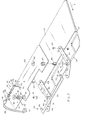
- the underlying visor body or panel 22 is coupled to a pair of dog leg- shaped, generally parallel pivot arms 32 and 34 by means of pivot fasteners 33 extending between one end of each of the arms 32 and 34 and a mounting bracket 36 to which the visor panel 22 is pivotally coupled by means of a pivot rod assembly 37 to permit fore and aft adjustment of the visor panel 22 when in a lowered position, as shown in Figure 1.
- the opposite ends of the pivot arms 32 and 34 are pivotally coupled to a cross arm 38 which is generally U-shaped having end tabs 39 slightly off-set from the body of the cross arm 38 and including apertures therein which align and are pivotally coupled to the opposite ends of the arms 32 and 34 by means of pivot fasteners40.
- the cross arm 38 which is mounted to the arms 32 and 34 in an off-set manner provides stability and ease of operation for the swing-down operation of the visor panel 22 when moved from a stored position concealed within the vehicle headliner to a lowered use position.
- the arms 32 and 34 are pivotally secured at spaced locations of the vehicle headliner and specifically to a sheet metal panel 42 by means of pivot pins 31 and 35 extending upwardly from the elbow portion of the arms 32 and 34, as shown in Figure 2.
- the pins 31 and 35 extend through sleeve bushings 41 and 45, respectively, which are, in turn, fitted within collars 43 and 47 welded or force fitted within the panel 42, as seen in Figure 2.
- the pivot pins 31 and 35 are held in position by means of C-shaped spring clips 44 and 46 which fit within annular grooves 31' and 35' formed near the upper edge of the pivot pins 31 and 35, respectively, when the unit is assembled (Figure 3).
- the panel 42 can be an integral part of the sheet metal headliner of the vehicle or, a separate assembly which in turn is fastened to the sheet metal roof of the vehicle in a known manner such as by sheet metal screws or the like.
- the visor assembly as seen in Figure 2, is shown in the lowered position and moves to such position about the pivot pins 31 and 35 in a direction indicated by arrow A, to move downwardly and slightly toward the side of the adjacent angled support post 13 ( Figure 1).
- Figure 1 When moved upwardly in a general direction indicated by arrow B, from the lowered use position to the stored position concealed within the vehicle headliner it rotates about the pins 31 and 35 in a direction opposite arrow A.
- the visor actuating mechanism 50 includes a coil spring 52 which has an inner diameter large enough to permit the spring to extend coaxially over collar 43, as seen in the installed position of Figure 3, with one end 51 of the spring inwardly turned along the centre thereof to fit within a notch 43' of collar 43 to anchor the spring and prevent rotation of the spring around the collar once installed.
- the C-spring clip 44 holds the spring in axial alignment over the collar, once installed, with the end 51 seated within the notch 43'.
- the opposite end or spring arm 53 of the spring 52 extends outwardly, as seen in Figure 2, and selectively engages a cam in the form of a pin 60 extending upwardly from a leg segment 61 of the arm 32.
- spring arm 53 When the visor is in the lowered position, as seen in Figure 2, spring arm 53 substantially disengages the pin 60 when, however, the visor is moved to a raised position, as illustrated in Figure 3, the pin 60 engages the spring arm 53 tending to rotate the arm in a direction indicated by arrow C to compress the coil spring which, in turn, provides a spring force in a direction indicated by arrow F in Figure 3 which, unless the arms are latched, urges the interconnected parallel arms 32 and 34 to pivot around the pivot pins 31 and 35 in a direction opposite arrows A and C, namely, toward a visor lowering position.
- the spring 52 is formed such that end 53 extendstangentially outwardly at a point along the outer periphery of the spring to disengage the pin 60 when the arm 32 has rotated about 90 0 corresponding to the visor being lowered approximately half-way. Thus, the spring end 53 will stop in the position shown in Figure 2.
- a latching assembly 70 In order to hold the visor in a concealed stored position and latched against the bias spring 52, a latching assembly 70 is provided and includes a !. latching bar 72 having one end pivotally coupled to the panel 42 by means of a pivot pin 71 ( Figure 2) and extending outwardly therefrom and including a pin receiving slot 74 for releasably engaging a latch pin 64 extending upwardly from the leg segment 61 of the pivot arm 32, as best seen in Figure 3.
- the latching bar 72 also includes an upwardly projecting pin 73 which is coupled to the end of a plunger 76 of an electrically operated solenoid 78.
- the solenoid 78 is mounted to the panel 42 by means of an angled mounting bracket 80 by known mounting means 82 and is spring loaded with the plunger 76 extending outwardly.
- the bracket 80 is, in turn, secured to the panel 42.
- the end of plunger 76 includes a slot 77 formed therein for receiving the pin 73 which is captively held therein by means of a transversely extending roll pin 81 extending in apertures on opposite edges of the slot 77 in the end of the plunger 76 to hold the pin 73 within the slot 77.
- the spring-loaded solenoid urges the latching arm into a latching position, as shown in Figure 3.
- the end of the latching 72, opposite the pivot pin 71, includes a curved camming surface 75 such that as the visor is manually returned to its stored position, the latch pin 64 will ride over the camming surface 73 permitting the latch arm to pivot and the pin 73 to extend into the slot 74.
- the solenoid 78 is electrically coupled to the vehicle's power system by means of a push-button switch 84 which, as seen in Figure 1, can be conveniently mounted to the vehicle headliner to be easily accessible by the vehicle occupant. Suitable interconnecting electrical wires 85 couple the switch 84 to the solenoid 78 as well and to the vehicle power source (not shown).
- the spring biasing of the visor control assembly and the releasable actuation of the spring-loading mechanism can be positioned on either of the arms 32 or 34 or at other locations between the moveable visor control elements and the stationary panel 42 or the vehicle itself.
Landscapes
- Engineering & Computer Science (AREA)
- Mechanical Engineering (AREA)
- Arrangements Of Lighting Devices For Vehicle Interiors, Mounting And Supporting Thereof, Circuits Therefore (AREA)
- Vehicle Step Arrangements And Article Storage (AREA)
- Rear-View Mirror Devices That Are Mounted On The Exterior Of The Vehicle (AREA)
- Acyclic And Carbocyclic Compounds In Medicinal Compositions (AREA)
- Luminescent Compositions (AREA)
Applications Claiming Priority (2)
| Application Number | Priority Date | Filing Date | Title |
|---|---|---|---|
| US06/453,530 US4492404A (en) | 1982-12-27 | 1982-12-27 | Visor actuating mechanism |
| US453530 | 1982-12-27 |
Publications (3)
| Publication Number | Publication Date |
|---|---|
| EP0112682A2 true EP0112682A2 (fr) | 1984-07-04 |
| EP0112682A3 EP0112682A3 (en) | 1984-11-21 |
| EP0112682B1 EP0112682B1 (fr) | 1986-11-12 |
Family
ID=23800918
Family Applications (1)
| Application Number | Title | Priority Date | Filing Date |
|---|---|---|---|
| EP83307570A Expired EP0112682B1 (fr) | 1982-12-27 | 1983-12-13 | Mécanisme d'actionnement pour pare-soleil |
Country Status (6)
| Country | Link |
|---|---|
| US (1) | US4492404A (fr) |
| EP (1) | EP0112682B1 (fr) |
| JP (1) | JPS59120516A (fr) |
| CA (1) | CA1203270A (fr) |
| DE (1) | DE3367561D1 (fr) |
| ES (1) | ES8503287A1 (fr) |
Families Citing this family (12)
| Publication number | Priority date | Publication date | Assignee | Title |
|---|---|---|---|---|
| US4762359A (en) * | 1984-11-02 | 1988-08-09 | Prince Corporation | Visor system |
| DE3541902A1 (de) * | 1985-11-27 | 1987-06-04 | Daimler Benz Ag | Blendschutzeinrichtung fuer kraftfahrzeuge |
| JP2572118B2 (ja) * | 1988-11-11 | 1997-01-16 | 日産自動車株式会社 | 自動車のサンバイザー装置 |
| US4929014A (en) * | 1988-12-27 | 1990-05-29 | Prince | Full windshield sunshade |
| US4958878A (en) * | 1989-08-21 | 1990-09-25 | Prince Corporation | Headliner with integral visor |
| US4989910A (en) * | 1990-01-31 | 1991-02-05 | Prince Corporation | Pivoted slide-out visor panel |
| US5219199A (en) * | 1990-10-26 | 1993-06-15 | Prince Corporation | Stabilized slide-out visor |
| US5192110A (en) * | 1991-08-30 | 1993-03-09 | United Technologies Automotive | Sunshade and vanity mirror system for a motor vehicle |
| US5186442A (en) * | 1992-01-28 | 1993-02-16 | Prince Corporation | Visor with double acting slide mechanism |
| US5211439A (en) * | 1992-03-31 | 1993-05-18 | Prince Corporation | Curvilinear sliding visor |
| US5186512A (en) * | 1992-04-16 | 1993-02-16 | Prince Corporation | Rear window sliding visor |
| DE19754533A1 (de) * | 1997-12-09 | 1999-06-10 | Johnson Contr Interiors Gmbh | Sonnenblendenachse |
Family Cites Families (9)
| Publication number | Priority date | Publication date | Assignee | Title |
|---|---|---|---|---|
| US2100427A (en) * | 1935-09-20 | 1937-11-30 | Samuel J Blocker | Automatic glare shield |
| US2101901A (en) * | 1936-09-26 | 1937-12-14 | Joseph H Fletcher | Glare shield |
| US2122120A (en) * | 1937-05-11 | 1938-06-28 | Martin H Thode | Antiglare shield mounting and operating means therefor |
| US2446866A (en) * | 1947-09-03 | 1948-08-10 | Bell Lee Alexander | Glare screen for motor vehicles |
| US2607906A (en) * | 1948-12-06 | 1952-08-19 | Victor S Sang | Automatic glare shield control |
| GB684364A (en) * | 1949-10-05 | 1952-12-17 | Augusto Christiano Hermano Are | Apparatus for the protection of a vehicle driver's vision against light rays |
| DE1014446B (de) * | 1954-04-28 | 1957-08-22 | Robert Chappatte | Verschwenkbarer Blendschutz gegen stoerendes Licht, insbesondere fuer Kraftfahrer |
| DE3105848A1 (de) * | 1981-02-18 | 1982-09-02 | Gebr. Happich Gmbh, 5600 Wuppertal | Anordnung einer sonnenblende oberhalb einer seitenscheibe in einem fahrzeug |
| US4491360A (en) * | 1982-07-30 | 1985-01-01 | Prince Corporation | Concealed visor |
-
1982
- 1982-12-27 US US06/453,530 patent/US4492404A/en not_active Expired - Fee Related
-
1983
- 1983-10-11 CA CA000438749A patent/CA1203270A/fr not_active Expired
- 1983-11-07 ES ES527058A patent/ES8503287A1/es not_active Expired
- 1983-11-30 JP JP58226730A patent/JPS59120516A/ja active Pending
- 1983-12-13 EP EP83307570A patent/EP0112682B1/fr not_active Expired
- 1983-12-13 DE DE8383307570T patent/DE3367561D1/de not_active Expired
Also Published As
| Publication number | Publication date |
|---|---|
| DE3367561D1 (en) | 1987-01-02 |
| EP0112682B1 (fr) | 1986-11-12 |
| EP0112682A3 (en) | 1984-11-21 |
| CA1203270A (fr) | 1986-04-15 |
| US4492404A (en) | 1985-01-08 |
| JPS59120516A (ja) | 1984-07-12 |
| ES527058A0 (es) | 1985-02-16 |
| ES8503287A1 (es) | 1985-02-16 |
Similar Documents
| Publication | Publication Date | Title |
|---|---|---|
| EP0112682B1 (fr) | Mécanisme d'actionnement pour pare-soleil | |
| US5590933A (en) | Folding headrest | |
| EP0712746B1 (fr) | Module pour porte de véhicule | |
| US5277080A (en) | Manually actuated furniture control | |
| US7866751B2 (en) | Apparatus and methods to integrally form lever operated cables with vehicle seats | |
| US5433509A (en) | Adjustable armrest | |
| US5529369A (en) | Door latches for golf carts and the like | |
| EP0126825B2 (fr) | Montage de pare-soleil | |
| GB2112346A (en) | Improvements in or relating to a device for raising various loads, particularly trolleys for handicapped persons, on vehicles | |
| EP0970846A1 (fr) | Appui-tête pour véhicule automobile | |
| US3967851A (en) | Push-on pivoted side arm for vehicle seat | |
| US4067613A (en) | Arm rest and mounting bracket therefor | |
| EP0100632B1 (fr) | Pare-soleil de véhicule | |
| US5765899A (en) | Lockable sliding visor | |
| US5307707A (en) | Manual cable-sheath control | |
| US5039153A (en) | Pivot down vanity mirror assembly | |
| GB2511599A (en) | Folding vehicle head restraint assembly | |
| US4189022A (en) | Automatically releasing seat belt anchor | |
| JP3091710B2 (ja) | 押しボタン遠隔制御装置 | |
| JP3482803B2 (ja) | シートバックテーブル装置 | |
| JPH0376253B2 (fr) | ||
| GB2263620A (en) | An actuator for an adjustable seat belt pillar loop | |
| JPH0255241B2 (fr) | ||
| KR100501036B1 (ko) | 자동차용 시트 슬라이드장치 | |
| KR850000132Y1 (ko) | 자동차용 시이트 |
Legal Events
| Date | Code | Title | Description |
|---|---|---|---|
| PUAI | Public reference made under article 153(3) epc to a published international application that has entered the european phase |
Free format text: ORIGINAL CODE: 0009012 |
|
| AK | Designated contracting states |
Designated state(s): DE FR GB IT |
|
| PUAL | Search report despatched |
Free format text: ORIGINAL CODE: 0009013 |
|
| AK | Designated contracting states |
Designated state(s): DE FR GB IT |
|
| 17P | Request for examination filed |
Effective date: 19850429 |
|
| 17Q | First examination report despatched |
Effective date: 19860207 |
|
| ITF | It: translation for a ep patent filed | ||
| GRAA | (expected) grant |
Free format text: ORIGINAL CODE: 0009210 |
|
| AK | Designated contracting states |
Kind code of ref document: B1 Designated state(s): DE FR GB IT |
|
| REF | Corresponds to: |
Ref document number: 3367561 Country of ref document: DE Date of ref document: 19870102 |
|
| ET | Fr: translation filed | ||
| PLBE | No opposition filed within time limit |
Free format text: ORIGINAL CODE: 0009261 |
|
| STAA | Information on the status of an ep patent application or granted ep patent |
Free format text: STATUS: NO OPPOSITION FILED WITHIN TIME LIMIT |
|
| 26N | No opposition filed | ||
| PGFP | Annual fee paid to national office [announced via postgrant information from national office to epo] |
Ref country code: GB Payment date: 19911118 Year of fee payment: 9 |
|
| PGFP | Annual fee paid to national office [announced via postgrant information from national office to epo] |
Ref country code: FR Payment date: 19911212 Year of fee payment: 9 |
|
| PGFP | Annual fee paid to national office [announced via postgrant information from national office to epo] |
Ref country code: DE Payment date: 19911227 Year of fee payment: 9 |
|
| ITTA | It: last paid annual fee | ||
| PG25 | Lapsed in a contracting state [announced via postgrant information from national office to epo] |
Ref country code: GB Effective date: 19921213 |
|
| GBPC | Gb: european patent ceased through non-payment of renewal fee |
Effective date: 19921213 |
|
| PG25 | Lapsed in a contracting state [announced via postgrant information from national office to epo] |
Ref country code: FR Effective date: 19930831 |
|
| PG25 | Lapsed in a contracting state [announced via postgrant information from national office to epo] |
Ref country code: DE Effective date: 19930901 |
|
| REG | Reference to a national code |
Ref country code: FR Ref legal event code: ST |