EP0112703B1 - Lichtanlage für Fahrzeuge - Google Patents
Lichtanlage für Fahrzeuge Download PDFInfo
- Publication number
- EP0112703B1 EP0112703B1 EP19830307703 EP83307703A EP0112703B1 EP 0112703 B1 EP0112703 B1 EP 0112703B1 EP 19830307703 EP19830307703 EP 19830307703 EP 83307703 A EP83307703 A EP 83307703A EP 0112703 B1 EP0112703 B1 EP 0112703B1
- Authority
- EP
- European Patent Office
- Prior art keywords
- lighting system
- dipped beam
- energised
- beam filaments
- switch
- Prior art date
- Legal status (The legal status is an assumption and is not a legal conclusion. Google has not performed a legal analysis and makes no representation as to the accuracy of the status listed.)
- Expired
Links
Images

Classifications
-
- B—PERFORMING OPERATIONS; TRANSPORTING
- B60—VEHICLES IN GENERAL
- B60Q—ARRANGEMENT OF SIGNALLING OR LIGHTING DEVICES, THE MOUNTING OR SUPPORTING THEREOF OR CIRCUITS THEREFOR, FOR VEHICLES IN GENERAL
- B60Q1/00—Arrangement of optical signalling or lighting devices, the mounting or supporting thereof or circuits therefor
- B60Q1/02—Arrangement of optical signalling or lighting devices, the mounting or supporting thereof or circuits therefor the devices being primarily intended to illuminate the way ahead or to illuminate other areas of way or environments
- B60Q1/04—Arrangement of optical signalling or lighting devices, the mounting or supporting thereof or circuits therefor the devices being primarily intended to illuminate the way ahead or to illuminate other areas of way or environments the devices being headlights
- B60Q1/14—Arrangement of optical signalling or lighting devices, the mounting or supporting thereof or circuits therefor the devices being primarily intended to illuminate the way ahead or to illuminate other areas of way or environments the devices being headlights having dimming means
- B60Q1/1415—Dimming circuits
Definitions
- This invention relates to a vehicle lighting system.
- the aforesaid device energises the dipped beam filaments as soon as the ignition switch is closed, which imposes a considerable current drain on the vehicle battery. If the battery is already at a low charge level (such as is often the case in winter when this particular system will be used the most, then the additional current drain imposed by the dipped beam filaments will make it difficult or even impossible to start the engine. It then becomes necessary to switch off the sidelights, which is not only dangerous for other motorists but may also be illegal.
- the present invention overcomes this problem by providing means which senses the voltage at a predetermined point in the charging circuit where the voltage varies as the speed of the engine increases and which activates the device only if the sidelights are energised and if the speed of the engine is sufficient to cause this voltage to pass through a preselected level.
- the dipped beam filaments do not therefore become energised until after the engine has been safely started, thereby avoiding premature current drain on the battery.
- the sidelights can be selectively energised and de-energised by means of a switch, and the said means is also responsive to the voltage appearing at a chosen point between the switch and the sidelights, said means being operative to actuate said device when the voltages at said predetermined point and said chosen point are at respective preselected levels.
- the device may include a diode connected between these two points to place a voltage clamp on the device until the said voltages are at said respective preselected levels.
- the lighting system comprises switch means which is manually operable to energise the dipped beam filaments of the headlamps, the dipped beam filaments being operated at substantially the same intensity when energised by said device as is the case when they are energised by said switch means.
- the dipped beam filaments may be operated at a reduced intensity when energised by said device than is the case when they are energised by said switch means, for example by connecting a resistance in series between said device and the dipped beam filaments, or (where the dipped beam filaments are energised by means of a pulsed electrical signal) by varying the mark/space ratio of the pulses in said signal.
- each headlamp can comprise a main beam filament, a first dipped beam filament which is energised by said device, and a second dipped beam filament which is energised by means of a manually operable switch, the first dipped beam filament being arranged to emit light at a lower intensity than the second dipped beam filament.
- the said device comprises an oscillator producing output pulses and a power switching circuit which is driven by the oscillator and which supplies pulses of electrical power to the dipped beam filaments. In this case, it is preferred that an initial output pulse from the oscillator is of longer duration than subsequent output pulses therefrom.
- the switching circuit can include first semiconductor switching means by means of which pulses are supplied to the dipped beam filaments when the latter are cold, and second semiconductor switching means by means of which pulses are supplied to the dipped beam filaments after the latter have heated up.
- the pulses supplied by the first semiconductor switching means are preferably reduced in power as compared with the pulses supplied by the second semiconductor switching means.
- a resistance can be provided in series between the first semiconductor switching means and the dipped beam filaments to limit the initial inrush current of the first semiconductor switching means.
- a control terminal of the second semiconductor switching means is connected to the main conduction path of a semiconductor switching element, the switching element being rendered conductive in response to an increase in the voltage drop across the dipped beam filaments as the latter heat up.
- the control terminal of the switching element can also be connected to the main conduction path of a further semiconductor switching element, with a charging circuit preventing said further switching element from becoming conductive until a predetermined time delay after the first semiconductor switching means supplies an initial pulse to the dipped beam filaments.
- said device also comprises a control circuit which renders the power switching circuit inoperative in response to the dipped beam filaments being short-circuited.
- This control circuit may include a charging unit which discharges when the second semiconductor switching means supplies a pulse to the dipped beam filaments and charges during the interpulse period, the time constant for such charging being substantially greater than the period of the output pulses from the oscillator, and a disabling circuit to disable the power circuit in the event that the charging circuit charges beyond a predetermined amount, corresponding to the second semiconductor switching means being out of operation for longer than the time normally taken for the dipped beam filaments to heat up.
- a control terminal of the first semiconductor switching means is connected to the main conduction path of a semiconductor switching element, the output pulses from the oscillator are applied to a control terminal of the switching element, and the disabling circuit is arranged to render the switching element non-conductive in the event of the charging circuit charging beyond said predetermined amount.
- the disabling circuit can include a further semiconductor switching element having its main conduction path connected to the control terminal of the first-mentioned switching element, the further switching element normally being non-conductive but being rendered conductive by charging of the charging circuit beyond said predetermined amount.
- said device includes a relay having a coil and switch contacts which are electrically connected to the dipped beam filaments, the coil being energised to operate the switch contacts when the charging circuit is operating and the main beam filaments are de-energised.
- the relay coil is preferably supplied with electricity at one terminal thereof which is voltage clamped at such a level as to prevent the switch contacts from being operated, unless the sidelights are energised whereupon said voltage clamping is removed.
- said one terminal of the relay coil is supplied with electricity from the charging circuit.
- the voltage clamping is performed by a diode having its anode electrically connected to said one terminal of the relay coil and its cathode electrically connected to a point between the sidelights and a switch by way of which the sidelights are energised.
- a diode has its anode electrically connected to the other terminal of the relay coil and its cathode electrically connected to a point between the main beam filaments and switch means by way of which these filaments are energised, said diode being effective to clamp the voltage at said other terminal of the relay coil at a low level until the main filaments are energised.
- the voltage drop across the relay coil rises to a level which is significantly higher than the threshold voltage drop required to operate the relay switch contacts.
- the said device includes a semiconductor switch having a main conduction path which is electrically connected between the relay coil and the main beam filaments and a control terminal which is electrically connected to the charging circuit, the semiconductor switch being rendered conductive when the charging circuit is operating and the main beam filaments are not energised.
- a diode is connected electrically in parallel with the relay coil to suppress inductive voltages.
- a capacitor may be connected electrically in parallel with the relay switch contacts to suppress arcing.
- a first switch is operable to energise the sidelights and is connected electrically in series with the relay coil
- a second switch is operable to energise selectively the main beam filaments and the dipped beam filaments
- the switch contacts of the relay are electrically connected between a power supply and a point between the second switch and the dipped beam filaments.
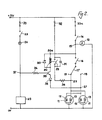
- the lighting system shown therein includes sidelights 10 (only one shown) and headlamps 11 each having a main beam filament 12 and a dipped beam filament 13.
- the sidelights 10 are electrically connected to a power supply (derived from a battery of the vehicle) by way of a switch 14, while the connection point (referenced 15) between the sidelights and the switch 14, is electrically connected by way of a further switch 16 to a movable switch contact 17.
- the contact 17 is engageable selectively with a first fixed contact 19 which is connected to the main beam filaments 12 of the headlamps, and with a second fixed contact 18 which is connected to the dipped beam filaments 13.
- a relay coil 20 has one terminal 20a thereof connected to the anode of a diode 21, the cathode of the diode being connected to the point 15.
- the terminal 20a of the coil 20 is also connected by way of a resistor 22 to a charging circuit of the vehicle, the charging circuit including an ignition switch 23, an ignition warning lamp 24 and an alternator or dynamo 25.
- the other terminal of the relay coil 20 is connected to the anode of a diode 26, which diode has its cathode connected to a point 27 between the contact 19 and the main beam filaments 12 of the headlamps 11.
- Contacts 28, which open and close according to the energisation state of the relay coil 20, are electrically connected between the power supply and a point 29 between the contact 18 and the dipped beam filaments 13 of the headlamps.
- the contacts 28 are normally open, but close when a current is passed through the relay coil 20.
- a diode 30 is connected electrically in parallel with the coil 20 to suppress inductive voltages when the contacts 28 open, while a capacitor 31 is connected electrically in parallel with the contacts 28 to suppress arcing.
- a fuse 32 is provided between the power supply and the contacts 28, while further fuses 33 and 33a are disposed respectively in the aforementioned charging circuit, and in the positive supply line to the switch 14.
- the above-described lighting system operates as follows.
- the ignition switch 23 is initially closed with the sidelights 10 off (i.e. the switch 14 open)
- a small voltage drop is developed across the alternator or dynamo 25 (about 1.2v for a 12v power supply).
- This voltage drop remains low once the engine has been started and is merely idling, but rapidly increases to substantially the voltage of the power supply when the engine is accelerated.
- the relay coil 20 is supplied with electricity from the alternator or dynamo 25 during this procedure, as long as the sidelights 10 remain off the diode 21 will clamp the terminal 20a of the coil 20 to a voltage which is insufficient to cause the contacts 28 to close.
- the voltage at the cathode of the diode 21 will rise substantially to the voltage of the power supply and the clamp will therefore be removed.
- the voltage at the terminal 20a of the relay coil 20 will then rise to a value dependent upon the relative resistances of the relay coil and the resistor 22: this value is chosen so as to be sufficient to cause the contacts 28 to close, so that the dipped beam filaments 13 become energised through those contacts.
- this value is chosen so as to be sufficient to cause the contacts 28 to close, so that the dipped beam filaments 13 become energised through those contacts.
- the relay has a nominal operating voltage of 6v, and the resistor 22 is chosen so as to have the same resistance as the relay coil 20.
- the contacts 28 close when the voltage across the relay coil 20 is only about 4.4v. Since the coil voltage is rising rapidly at this point, very positive operation of the contacts 28 occurs so that there is no chance of any contact sizzle.
- the relay will operate only when the alternator or dynamo 25 is producing an output, the sidelights 10 are on and the main beam filaments 12 are off.
- the dipped beam filaments 13 may operate at a reduced intensity when energised via the relay contacts 28 as compared with when they are energised by way of the switches 14, 16 and the switch contacts 17, 18.
- a ballast resistance 34 (shown in broken lines) can be incorporated between the contacts 28 and the point 29.
- a second embodiment of the invention is shown in Figure 2, and is generally similar to the system shown in Figure 1, similar parts being accorded the same reference numerals.
- the diode 21 and the resistor 22 are omitted and the terminal 20a of the relay coil 20 is instead connected directly to the point 15.
- a transistor 35 is now provided, such that its collector-emitter path is connected between the other terminal of the relay coil 20 and the point 27.
- the base of the transistor 35 is connected by way of a resistor 36 to a point 37 between the ignition warning lamp 24 and the alternator or dynamo 25.
- a ballast resistance 34 may be provided so that the dipped beam filaments 13 are operated at a reduced intensity when they are energised by way of the relay contacts 28.
- the contact 17 is engaged with the fixed contact 19 with the switches 14 and 16 once again being closed. This causes the voltage at the point 27 to rise substantially to the level of the power supply, so that the relay coil 20 becomes de-energised. Hence, the contacts 28 open and the dipped beam filaments 13 are turned off.
- the diode 38 in the emitter circuit of the transistor 35 prevents a reverse voltage from occurring across the base-emitter junction of the transistor if the main beam filaments 12 are energised and the alternator or dynamo 25 is not charging.
- the relay circuit has been described as being associated with the alternator or dynamo of a vehicle.
- the relay circuit could be associated with an oil pressure warning circuit of the vehicle, in which case the base of the transistor 35 would be connected to a point between an oil pressure switch and an oil pressure warning lamp, instead of to a point between the ignition warning lamp and the alternator or dynamo.
- a series resistor 34 is employed to achieve dimming of the dipped beam filaments 13 when they are energised via the relay as compared with when they are energised via the switch 16 and the switch contacts 17, 18. This is quite satisfactory when only a limited reduction in intensity is required, but for greater intensity reductions the resistor 34 will have to dissipate relatively large amounts of power and therefore becomes more expensive to provide.
- a system as shown in Figure 3 may be used instead.
- the dipped beam filaments are powered by a pulsed electrical supply and their intensity is controlled by suitably varying the ratio between the "ON" and "OFF" periods.
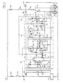
- the system illustrated in Figure 3 comprises generally an oscillator circuit 40 which controls a power switching circuit 41 supplying power to the dipped beam filaments 13, and a control circuit 42 to protect the system in the event that the filaments 13 become short-circuited.
- the oscillator circuit 40 is supplied from a point between the warning lamp 24 and the alternator 25 by way of a resistor 43, a zener diode 44 and a capacitor 45 which together form a stabilised power supply. When the engine is not running, the output voltage produced by this power supply will be very low and the oscillator circuit 40 will not function.
- a diode 46 connected between the sidelights and the resistor 43 will clamp the output voltage of the power supply to a level (e.g. 1 volt) which is still insufficient to cause the oscillator circuit 40 to operate. However, if the sidelights 10 are now switched on, the output voltage of the power supply will rise to a relatively large value (e.g. 10 volts).
- a diode 47 is connected between the negative side of the oscillator circuit 40 and the main beam filaments 12: if these filaments are not energised, then the oscillator circuit will be connected to battery negative via the diode 47 and the filaments 12, and hence the oscillator circuit will function.
- the diode 47 will be reverse-biassed and the oscillator circuit 40 will cease to operate.
- the oscillator circuit is operational only when the engine is running, the sidelights 10 are switched on and the main beam filaments 12 are turned off.
- the oscillator circuit 40 is composed of an integrated timer circuit 48 which is connected for astable operation: in the illustrated arrangement, the timer circuit is of the well-known 555 type and therefore the pin connections thereof will not be described in detail since these will readily be appreciated by a person skilled in the art. Suffice ,it to say that pin 3 forms an output terminal of the oscillator circuit.
- a capacitor 49 charges by way of a variable resistor 50 and a diode 51 until the voltage across it reaches a predetermined value (in this case, two-thirds of the supply voltage). At this point, the voltage at the output terminal drops to a low level and the capacitor 49 discharges via a resistor 52 into pin 7 of the timer circuit 48.
- the voltage produced at the output terminal of the oscillator circuit 40 thus consists of a series of pulses whose width can be controlled by adjusting the variable resistor 50.
- the initial voltage pulse is made much wider by means of a resistor 53, a capacitor 54 and a diode 55. More particularly, as soon as the supply voltage for the oscillator circuit starts to rise as aforesaid when the engine is running and the sidelights are switched on, the capacitor 54 will start to charge at a rate determined by the time constant of the capacitor 54 and the resistor 53. This time constant is made much longer than that of the variable resistor 50 and the capacitor 49, which may be for example 300 ms as compared with 10 ms for the last-mentioned components, depending upon the illumination intensity required for the dipped beam filaments 13.
- the power switching circuit 41 includes a transistor 56 whose base is connected to the output terminal of the oscillator circuit 40 by way of a resistor 57.
- the collector of the transisotr 56 is connected by way of a resistor 58 to a Darlington transistor 59, the latter having its emitter connected to a point 60 between the warning lamp 24 and the ignition switch 23.
- the collector of transistor 59 is connected by way of resistors 61 and 62 to the dipped beam filaments 13 of the headlamps 11, the connection point between the resistors 61 and 62 being coupled to the emitter of a transisotr 63 via a resistor 64 and a diode 65.
- the base of the transistor 63 is connected to the collector of the transistor 56 by way of a resistor 66, while the collector of the transistor 63 is connected to the base of a transistor 67.
- This last-mentioned transistor has its emitter connected to a connection point between a zener diode 68 and a resistor 69, these latter components being connected in series with the main beam filaments 12.
- the collector of the transistor 67 is connected via a resistor 70 to the base of a further Darlington transistor 71.
- the collector emitter path of the Darlington transistor 71 is connected directly between the ignition switch 23 and the dipped beam filaments 13.
- the transistor 56 When a voltage pulse appears at the output terminal of the oscillator circuit 40, the transistor 56 is turned on and allows base current to flow out of the Darlington transistor 59. Collector current will then flow from the transistor 59 to the dipped beam filaments 13 via the resistors 61 and 62. Initially, the filaments 13 are cold and have a very low resistance, typically 0.25 ohms. If the resistors 61 and 62 were not provided then the inrush current to the cold filaments would be much higher than the rated current of the Darlington transistor 59 (being for example as much as 50 amps). The resistors 61 and 62 serve to limit this initial current to a safe value, e.g. 6 amps.
- the voltage at the connection point between the resistors 61 and 62 is at such a value that current can flow through the base-emitter junction of the transistor 63 by way of the resistor 64, the diode 65 and the resistor 66, but not through the emitter-collector path of the transistor 63.
- their resistance increases thereby causing the voltage at the connection point between the resistors 61 and 62 to rise.
- this voltage has risen sufficiently, current will flow via the resistor 64, the diode 65 and the emitter-collector path of the transistor 63 into the base of the transistor 67, thereby turning the latter on.
- the transistor 56 will switch off, thereby causing the Darlington transistors 59 and 71 to switch off also so that current supply to the dipped beam filaments 13 is suspended until the start of the next voltage pulse.
- the increased width of the first pulse will ensure that the dipped beam filaments 13 are energised long enough for them to become heated up. If the width of the first pulse were not to be increased in the above-described manner, then there is a danger that the filaments 13 would never heat up sufficiently to bring the Darlington transistor 71 into operation.
- a capacitor 73 is connected between the emitters of the Darlington transistors 59, 71 and the feed to the dipped beam filaments 13 in order to protect the system from external voltage transients.
- the power switching circuit 41 should not operate in the event that the dipped beam filaments 13 become short-circuited. However, it is not possible to use the resistance across the dipped beam filaments to determine whether or not a short-circuit is present, since the resistance of healthy filaments is practically zero when they are cold anyway. It is for this reason that the circuit 42 is provided.
- the circuit 42 comprises a capacitor 74 and a resistor 75 connected in series between the output of the previously-described stabilised power supply and the collector of the Darlington transistor 71, the resistor 75 being connected in parallel with a series circuit of a resistor 76 and a diode 77.
- the connection point between the capacitor 74 and the resistor 75 is coupled on the one hand by way of a resistor 78 to the main beam filaments 12 and on the other hand by way of a resistor 79 to the base of a transistor 80.
- the collector of the transistor 80 is connected to the output of the stabilised voltage supply via a resistor 81, while its emitter is connected to the anode of the diode 47.
- a further transistor 82 has its base connected to the collector of the transistor 80 and its collector-emitter path connected between the diode 47 and a point between the resistor 57 and the transistor 56.
- the voltage across the Darlington transistor 71 will switch between a relatively low value (e.g. 1.4 volts) when on and a relatively high value (e.g. 12 volts) when off.
- the capacitor 74 will charge via the resistor 75: during the "on” period the capacitor 74 will discharge by way of the resistor 43, the warning lamp 24, the emitter-collector path of the Darlington transistor 71, the resistor 76 and the diode 77.
- the time constant for charging is made significantly larger than that for discharging, and both of these are much longer than the periodic time of the oscillator circuit 40. This results in the voltage waveform across the capacitor 74 lying within a range (e.g. between 2 and 4 volts) which is sufficient to maintain the transistor 80 in continuous conduction.
- the collector voltage of the transistor 80 as applied to the base of the transistor 82 is therefore low enough to clamp the latter transistor in a non-conductive state.
- the voltage at the connection point between the resistors 61 and 62 will not rise in the manner described previously, and therefore the Darlington transistor 71 will not be switched on although the other Darlington transistor 59 will pulse as before and feed current into the short-circuit by way of the resistors 61 and 62.
- the capacitor 74 will charge continuously via the resistor 75: when the capacitor 74 becomes fully charged, it will no longer be able to feed base current into the transistor 80, which will therefore turn off and remove the clamp from the transistor 82. This latter transistor will then conduct and thereby clamp the base of the transistor 56, so that the flow of base current from the Darlington transistor 59 is permanently suspended and the latter remains turned off.
- the lighting system will remain in a quiescent state until either the ignition switch 23 or the sidelights 10 are turned off. This will cause the output of the stabilised power supply to drop to a low level or zero, whereupon the capacitor 74 will discharge via the resistor 43, the alternator 25, the dipped beam filaments 13, the resistor 76 and the diode 77 (in the case where the ignition switch is turned off), or via the diode 46, the sidelights 10, the dipped beam filaments 13, the resistor 76 and the diode 77 (in the case where the sidelights are turned off).
- the output of the stabilised power supply will return to its normal operational level and the system will resume its normal functioning.
- the resistor 78 is provided to prevent the capacitor 74 from charging to the point where the transistor 82 is turned on when the main beam filaments are energised, so that the circuit 42 does not sense the cold dipped beam filaments as being short-circuited under this condition. This ensures that the oscillator circuit will revert to normal operation and cause pulsing of the dipped beam filaments as soon as the main beam filaments are switched off.
- the resistor 78 allows the capacitor 74 to charge more during normal operation of the system than would be the case if the resistor 78 were omitted, the values of the various circuit components can be chosen to ensure that this does not present any problems.
- circuits 40, 41 and 42 are additional to the usual components of the vehicle lighting system and in no way interfere with these components.
- the power dissipation within these circuits is very low compared with the use of a series resistor, and hence the system can operate at a much higher efficiency.
- the lighting system shown in Figure 3 is suitable for both 12 volt and 24 volt operation.
Landscapes
- Engineering & Computer Science (AREA)
- Mechanical Engineering (AREA)
- Lighting Device Outwards From Vehicle And Optical Signal (AREA)
Claims (29)
Priority Applications (1)
| Application Number | Priority Date | Filing Date | Title |
|---|---|---|---|
| AT83307703T ATE24156T1 (de) | 1982-12-22 | 1983-12-19 | Lichtanlage fuer fahrzeuge. |
Applications Claiming Priority (4)
| Application Number | Priority Date | Filing Date | Title |
|---|---|---|---|
| GB8236389 | 1982-12-22 | ||
| GB8236389 | 1982-12-22 | ||
| GB8305057 | 1983-02-23 | ||
| GB838305057A GB8305057D0 (en) | 1983-02-23 | 1983-02-23 | Vehicle lighting system |
Publications (3)
| Publication Number | Publication Date |
|---|---|
| EP0112703A1 EP0112703A1 (de) | 1984-07-04 |
| EP0112703B1 true EP0112703B1 (de) | 1986-12-10 |
| EP0112703B2 EP0112703B2 (de) | 1992-11-25 |
Family
ID=26284753
Family Applications (1)
| Application Number | Title | Priority Date | Filing Date |
|---|---|---|---|
| EP19830307703 Expired EP0112703B2 (de) | 1982-12-22 | 1983-12-19 | Lichtanlage für Fahrzeuge |
Country Status (3)
| Country | Link |
|---|---|
| EP (1) | EP0112703B2 (de) |
| DE (1) | DE3368239D1 (de) |
| GB (1) | GB2133231B (de) |
Families Citing this family (2)
| Publication number | Priority date | Publication date | Assignee | Title |
|---|---|---|---|---|
| GB8531853D0 (en) * | 1985-12-30 | 1986-02-05 | Danor Electronics Ltd | Vehicle lighting system |
| GB2219896A (en) * | 1988-06-14 | 1989-12-20 | Bosch Gmbh Robert | Operating incandescent light bulbs to prevent surge currents |
Family Cites Families (6)
| Publication number | Priority date | Publication date | Assignee | Title |
|---|---|---|---|---|
| GB1074627A (en) * | 1963-05-24 | 1967-07-05 | Nat Res Dev | Road vehicle headlight systems |
| GB1092712A (en) * | 1964-03-16 | 1967-11-29 | Lucas Industries Ltd | Lighting systems for road vehicles |
| GB1078961A (en) * | 1965-03-22 | 1967-08-09 | Stellar Components Ltd | Improvements in or relating to dimmed headlight systems |
| GB1209301A (en) * | 1966-07-08 | 1970-10-21 | Essex Internat Inc | Headlight system for vehicles |
| FR2497484A1 (fr) * | 1981-01-07 | 1982-07-09 | Renault | Circuit de commande des feux d'un vehicule automobile |
| FR2511958A1 (fr) * | 1981-09-03 | 1983-03-04 | Ducellier & Cie | Dispositif d'obtention d'un eclairage code pour la circulation urbaine |
-
1983
- 1983-12-19 GB GB08333719A patent/GB2133231B/en not_active Expired
- 1983-12-19 DE DE8383307703T patent/DE3368239D1/de not_active Expired
- 1983-12-19 EP EP19830307703 patent/EP0112703B2/de not_active Expired
Also Published As
| Publication number | Publication date |
|---|---|
| GB2133231A (en) | 1984-07-18 |
| EP0112703A1 (de) | 1984-07-04 |
| GB8333719D0 (en) | 1984-01-25 |
| EP0112703B2 (de) | 1992-11-25 |
| GB2133231B (en) | 1986-05-21 |
| DE3368239D1 (en) | 1987-01-22 |
Similar Documents
| Publication | Publication Date | Title |
|---|---|---|
| US4684819A (en) | Vehicle daytime running lamps | |
| USRE34886E (en) | Electrical system for vehicle daytime running lights | |
| US5081565A (en) | Daytime running light system | |
| US4667129A (en) | Method and device for automatically switching on and off the headlights of a motor vehicle | |
| EP0014537A2 (de) | Richtungsanzeiger für Fahrzeuge | |
| US4723095A (en) | Daytime running lights using turn signal lamps | |
| US5646485A (en) | Motor vehicle daytime running light system having buck switch mode converter | |
| EP0112703B1 (de) | Lichtanlage für Fahrzeuge | |
| US4841199A (en) | Electrical system for vehicle daytime running lights | |
| US4899083A (en) | Automatic lighting system for automobile | |
| JP2008126958A (ja) | 可変負荷型点灯回路 | |
| US3422421A (en) | Blinker type signal system with indication of defective blinker lamp | |
| US6420832B2 (en) | Switching circuit with overload protection | |
| US5170097A (en) | Intermittent windshield wiper and headlight control | |
| US3569780A (en) | Transistorized flasher circuit | |
| US3858088A (en) | D. c. flasher | |
| US4105927A (en) | Device for adjusting the level of brightness emitted by a lamp | |
| JPH0810969B2 (ja) | 車両用交流発電機の制御装置 | |
| US3430100A (en) | Auxiliary safety magnetic lighting circuit for vehicles | |
| WO1990016139A1 (en) | Automatic brake light flashing electric module and circuit | |
| GB2184872A (en) | Vehicle lighting system | |
| GB1564504A (en) | Headlamp control system | |
| EP0340777B1 (de) | Betriebsschaltung | |
| EP0005330A2 (de) | Beleuchtungsanlage | |
| EP0109730A1 (de) | Schaltanordnung für Fahrtrichtungsblinkleuchten |
Legal Events
| Date | Code | Title | Description |
|---|---|---|---|
| PUAI | Public reference made under article 153(3) epc to a published international application that has entered the european phase |
Free format text: ORIGINAL CODE: 0009012 |
|
| AK | Designated contracting states |
Designated state(s): AT BE CH DE FR IT LI LU NL SE |
|
| 17P | Request for examination filed |
Effective date: 19840625 |
|
| GRAA | (expected) grant |
Free format text: ORIGINAL CODE: 0009210 |
|
| AK | Designated contracting states |
Kind code of ref document: B1 Designated state(s): AT BE CH DE FR IT LI LU NL SE |
|
| PG25 | Lapsed in a contracting state [announced via postgrant information from national office to epo] |
Ref country code: NL Effective date: 19861210 Ref country code: AT Effective date: 19861210 |
|
| REF | Corresponds to: |
Ref document number: 24156 Country of ref document: AT Date of ref document: 19861215 Kind code of ref document: T |
|
| PG25 | Lapsed in a contracting state [announced via postgrant information from national office to epo] |
Ref country code: SE Effective date: 19861231 |
|
| REF | Corresponds to: |
Ref document number: 3368239 Country of ref document: DE Date of ref document: 19870122 |
|
| ITF | It: translation for a ep patent filed | ||
| ET | Fr: translation filed | ||
| NLV1 | Nl: lapsed or annulled due to failure to fulfill the requirements of art. 29p and 29m of the patents act | ||
| PLBI | Opposition filed |
Free format text: ORIGINAL CODE: 0009260 |
|
| 26 | Opposition filed |
Opponent name: HELLA KG HUECK & CO. Effective date: 19870901 |
|
| ITTA | It: last paid annual fee | ||
| PUAH | Patent maintained in amended form |
Free format text: ORIGINAL CODE: 0009272 |
|
| STAA | Information on the status of an ep patent application or granted ep patent |
Free format text: STATUS: PATENT MAINTAINED AS AMENDED |
|
| 27A | Patent maintained in amended form |
Effective date: 19921125 |
|
| AK | Designated contracting states |
Kind code of ref document: B2 Designated state(s): AT BE CH DE FR IT LI LU NL SE |
|
| ITF | It: translation for a ep patent filed | ||
| ET3 | Fr: translation filed ** decision concerning opposition | ||
| EPTA | Lu: last paid annual fee | ||
| PGFP | Annual fee paid to national office [announced via postgrant information from national office to epo] |
Ref country code: FR Payment date: 19951212 Year of fee payment: 13 |
|
| PGFP | Annual fee paid to national office [announced via postgrant information from national office to epo] |
Ref country code: DE Payment date: 19951222 Year of fee payment: 13 |
|
| PGFP | Annual fee paid to national office [announced via postgrant information from national office to epo] |
Ref country code: LU Payment date: 19960101 Year of fee payment: 13 |
|
| PGFP | Annual fee paid to national office [announced via postgrant information from national office to epo] |
Ref country code: CH Payment date: 19960125 Year of fee payment: 13 |
|
| PGFP | Annual fee paid to national office [announced via postgrant information from national office to epo] |
Ref country code: BE Payment date: 19960130 Year of fee payment: 13 |
|
| APAC | Appeal dossier modified |
Free format text: ORIGINAL CODE: EPIDOS NOAPO |
|
| APAC | Appeal dossier modified |
Free format text: ORIGINAL CODE: EPIDOS NOAPO |
|
| PG25 | Lapsed in a contracting state [announced via postgrant information from national office to epo] |
Ref country code: LU Free format text: LAPSE BECAUSE OF NON-PAYMENT OF DUE FEES Effective date: 19961219 |
|
| PG25 | Lapsed in a contracting state [announced via postgrant information from national office to epo] |
Ref country code: LI Effective date: 19961231 Ref country code: CH Effective date: 19961231 Ref country code: BE Effective date: 19961231 |
|
| BERE | Be: lapsed |
Owner name: DANOR ELECTRONICS LTD Effective date: 19961231 |
|
| REG | Reference to a national code |
Ref country code: CH Ref legal event code: PL |
|
| PG25 | Lapsed in a contracting state [announced via postgrant information from national office to epo] |
Ref country code: FR Effective date: 19970829 |
|
| PG25 | Lapsed in a contracting state [announced via postgrant information from national office to epo] |
Ref country code: DE Effective date: 19970902 |
|
| REG | Reference to a national code |
Ref country code: FR Ref legal event code: ST |
|
| APAH | Appeal reference modified |
Free format text: ORIGINAL CODE: EPIDOSCREFNO |