EP0112763A1 - Hochspannungsversorgungseinrichtung für eine Last wie zum Beispiel für einen Röntgengenerator - Google Patents
Hochspannungsversorgungseinrichtung für eine Last wie zum Beispiel für einen Röntgengenerator Download PDFInfo
- Publication number
- EP0112763A1 EP0112763A1 EP83402407A EP83402407A EP0112763A1 EP 0112763 A1 EP0112763 A1 EP 0112763A1 EP 83402407 A EP83402407 A EP 83402407A EP 83402407 A EP83402407 A EP 83402407A EP 0112763 A1 EP0112763 A1 EP 0112763A1
- Authority
- EP
- European Patent Office
- Prior art keywords
- inverter
- controlled
- voltage
- load
- switching means
- Prior art date
- Legal status (The legal status is an assumption and is not a legal conclusion. Google has not performed a legal analysis and makes no representation as to the accuracy of the status listed.)
- Withdrawn
Links
- 230000001105 regulatory effect Effects 0.000 claims description 5
- 230000003068 static effect Effects 0.000 claims description 3
- 239000003990 capacitor Substances 0.000 description 20
- 230000008033 biological extinction Effects 0.000 description 6
- 238000004804 winding Methods 0.000 description 6
- 238000001914 filtration Methods 0.000 description 5
- 230000000630 rising effect Effects 0.000 description 3
- 238000010586 diagram Methods 0.000 description 2
- 238000011084 recovery Methods 0.000 description 2
- 230000001960 triggered effect Effects 0.000 description 2
- 238000010200 validation analysis Methods 0.000 description 2
- 230000004913 activation Effects 0.000 description 1
- 230000000903 blocking effect Effects 0.000 description 1
- 230000001276 controlling effect Effects 0.000 description 1
- 230000003247 decreasing effect Effects 0.000 description 1
- 230000010355 oscillation Effects 0.000 description 1
Images
Classifications
-
- H—ELECTRICITY
- H05—ELECTRIC TECHNIQUES NOT OTHERWISE PROVIDED FOR
- H05G—X-RAY TECHNIQUE
- H05G1/00—X-ray apparatus involving X-ray tubes; Circuits therefor
- H05G1/08—Electrical details
- H05G1/10—Power supply arrangements for feeding the X-ray tube
- H05G1/20—Power supply arrangements for feeding the X-ray tube with high-frequency AC; with pulse trains
-
- H—ELECTRICITY
- H02—GENERATION; CONVERSION OR DISTRIBUTION OF ELECTRIC POWER
- H02M—APPARATUS FOR CONVERSION BETWEEN AC AND AC, BETWEEN AC AND DC, OR BETWEEN DC AND DC, AND FOR USE WITH MAINS OR SIMILAR POWER SUPPLY SYSTEMS; CONVERSION OF DC OR AC INPUT POWER INTO SURGE OUTPUT POWER; CONTROL OR REGULATION THEREOF
- H02M3/00—Conversion of DC power input into DC power output
- H02M3/22—Conversion of DC power input into DC power output with intermediate conversion into AC
- H02M3/24—Conversion of DC power input into DC power output with intermediate conversion into AC by static converters
- H02M3/28—Conversion of DC power input into DC power output with intermediate conversion into AC by static converters using discharge tubes with control electrode or semiconductor devices with control electrode to produce the intermediate AC
- H02M3/305—Conversion of DC power input into DC power output with intermediate conversion into AC by static converters using discharge tubes with control electrode or semiconductor devices with control electrode to produce the intermediate AC using devices of a thyratron or thyristor type requiring extinguishing means
- H02M3/315—Conversion of DC power input into DC power output with intermediate conversion into AC by static converters using discharge tubes with control electrode or semiconductor devices with control electrode to produce the intermediate AC using devices of a thyratron or thyristor type requiring extinguishing means using semiconductor devices only
- H02M3/3155—Conversion of DC power input into DC power output with intermediate conversion into AC by static converters using discharge tubes with control electrode or semiconductor devices with control electrode to produce the intermediate AC using devices of a thyratron or thyristor type requiring extinguishing means using semiconductor devices only with automatic control of the output voltage or current
-
- H—ELECTRICITY
- H02—GENERATION; CONVERSION OR DISTRIBUTION OF ELECTRIC POWER
- H02M—APPARATUS FOR CONVERSION BETWEEN AC AND AC, BETWEEN AC AND DC, OR BETWEEN DC AND DC, AND FOR USE WITH MAINS OR SIMILAR POWER SUPPLY SYSTEMS; CONVERSION OF DC OR AC INPUT POWER INTO SURGE OUTPUT POWER; CONTROL OR REGULATION THEREOF
- H02M7/00—Conversion of AC power input into DC power output; Conversion of DC power input into AC power output
- H02M7/42—Conversion of DC power input into AC power output without possibility of reversal
- H02M7/44—Conversion of DC power input into AC power output without possibility of reversal by static converters
- H02M7/48—Conversion of DC power input into AC power output without possibility of reversal by static converters using discharge tubes with control electrode or semiconductor devices with control electrode
- H02M7/505—Conversion of DC power input into AC power output without possibility of reversal by static converters using discharge tubes with control electrode or semiconductor devices with control electrode using devices of a thyratron or thyristor type requiring extinguishing means
- H02M7/515—Conversion of DC power input into AC power output without possibility of reversal by static converters using discharge tubes with control electrode or semiconductor devices with control electrode using devices of a thyratron or thyristor type requiring extinguishing means using semiconductor devices only
- H02M7/5152—Conversion of DC power input into AC power output without possibility of reversal by static converters using discharge tubes with control electrode or semiconductor devices with control electrode using devices of a thyratron or thyristor type requiring extinguishing means using semiconductor devices only with separate extinguishing means
-
- H—ELECTRICITY
- H02—GENERATION; CONVERSION OR DISTRIBUTION OF ELECTRIC POWER
- H02M—APPARATUS FOR CONVERSION BETWEEN AC AND AC, BETWEEN AC AND DC, OR BETWEEN DC AND DC, AND FOR USE WITH MAINS OR SIMILAR POWER SUPPLY SYSTEMS; CONVERSION OF DC OR AC INPUT POWER INTO SURGE OUTPUT POWER; CONTROL OR REGULATION THEREOF
- H02M7/00—Conversion of AC power input into DC power output; Conversion of DC power input into AC power output
- H02M7/42—Conversion of DC power input into AC power output without possibility of reversal
- H02M7/44—Conversion of DC power input into AC power output without possibility of reversal by static converters
- H02M7/48—Conversion of DC power input into AC power output without possibility of reversal by static converters using discharge tubes with control electrode or semiconductor devices with control electrode
- H02M7/505—Conversion of DC power input into AC power output without possibility of reversal by static converters using discharge tubes with control electrode or semiconductor devices with control electrode using devices of a thyratron or thyristor type requiring extinguishing means
- H02M7/515—Conversion of DC power input into AC power output without possibility of reversal by static converters using discharge tubes with control electrode or semiconductor devices with control electrode using devices of a thyratron or thyristor type requiring extinguishing means using semiconductor devices only
- H02M7/523—Conversion of DC power input into AC power output without possibility of reversal by static converters using discharge tubes with control electrode or semiconductor devices with control electrode using devices of a thyratron or thyristor type requiring extinguishing means using semiconductor devices only with LC-resonance circuit in the main circuit
- H02M7/5233—Conversion of DC power input into AC power output without possibility of reversal by static converters using discharge tubes with control electrode or semiconductor devices with control electrode using devices of a thyratron or thyristor type requiring extinguishing means using semiconductor devices only with LC-resonance circuit in the main circuit the commutation elements being in a push-pull arrangement
- H02M7/5236—Conversion of DC power input into AC power output without possibility of reversal by static converters using discharge tubes with control electrode or semiconductor devices with control electrode using devices of a thyratron or thyristor type requiring extinguishing means using semiconductor devices only with LC-resonance circuit in the main circuit the commutation elements being in a push-pull arrangement in a series push-pull arrangement
-
- H—ELECTRICITY
- H05—ELECTRIC TECHNIQUES NOT OTHERWISE PROVIDED FOR
- H05G—X-RAY TECHNIQUE
- H05G1/00—X-ray apparatus involving X-ray tubes; Circuits therefor
- H05G1/08—Electrical details
- H05G1/26—Measuring, controlling or protecting
- H05G1/30—Controlling
- H05G1/32—Supply voltage of the X-ray apparatus or tube
Definitions
- the invention overcomes all of these drawbacks.
- the operating frequency of the inverter can be adjusted once and for all slightly lower than the resonance frequency of the above-mentioned oscillating circuit, which makes it possible to obtain a reduced residual ripple rate for the entire range of voltage variations. of the power system.
- the rectifier bridge is a simple Graetz diode bridge, which eliminates the use of expensive thyristors at this level.
- a single regulation loop controls the operation of the chopper.
- the operating frequency of the latter is high, of the order of a few kHz. Its speed of response is therefore much better than that of a Graetz bridge with thyristors operating at the network frequency.
- filtering is easier at this frequency and vis-à-vis the network, the system has better cos ⁇
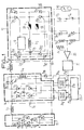
- the common point of the resistors R 1 and R2 is connected to an input of a differential amplifier 20 which receives on its other input a reference voltage adjustable by a potentiometer P 1 .
- the output of amplifier 20 is connected to a conventional circuit 21 forming a driving pulse generator.
- These pulses of variable duration control thyristor Th 1 The triggering of the thyristor is controlled in synchronism with each rising edge of the pulse while the blocking of this same thyristor is controlled from each falling edge.
Landscapes
- Engineering & Computer Science (AREA)
- Power Engineering (AREA)
- Health & Medical Sciences (AREA)
- General Health & Medical Sciences (AREA)
- Toxicology (AREA)
- X-Ray Techniques (AREA)
- Inverter Devices (AREA)
Applications Claiming Priority (2)
| Application Number | Priority Date | Filing Date | Title |
|---|---|---|---|
| FR8221398 | 1982-12-21 | ||
| FR8221398A FR2538183A1 (fr) | 1982-12-21 | 1982-12-21 | Systeme d'alimentation haute tension d'une charge telle que par exemple un generateur de rayons x |
Publications (1)
| Publication Number | Publication Date |
|---|---|
| EP0112763A1 true EP0112763A1 (de) | 1984-07-04 |
Family
ID=9280323
Family Applications (1)
| Application Number | Title | Priority Date | Filing Date |
|---|---|---|---|
| EP83402407A Withdrawn EP0112763A1 (de) | 1982-12-21 | 1983-12-13 | Hochspannungsversorgungseinrichtung für eine Last wie zum Beispiel für einen Röntgengenerator |
Country Status (3)
| Country | Link |
|---|---|
| US (1) | US4652985A (de) |
| EP (1) | EP0112763A1 (de) |
| FR (1) | FR2538183A1 (de) |
Cited By (4)
| Publication number | Priority date | Publication date | Assignee | Title |
|---|---|---|---|---|
| FR2570230A1 (fr) * | 1984-09-12 | 1986-03-14 | Trailigaz | Dispositif de commutation forcee d'un onduleur et dispositif d'alimentation d'un ozoneur en comportant application |
| FR2572859A1 (fr) * | 1984-11-06 | 1986-05-09 | Electricite De France | Onduleur a thyristors comportant un circuit de protection contre les defauts |
| EP0226256A1 (de) * | 1985-12-18 | 1987-06-24 | Océ-Nederland B.V. | Ladungsschaltung für Energie-Speicherungs-Kapazitäten |
| CN102435800A (zh) * | 2011-11-07 | 2012-05-02 | 四川中物海通特种电源有限责任公司 | 一种高压脉冲发生器 |
Families Citing this family (13)
| Publication number | Priority date | Publication date | Assignee | Title |
|---|---|---|---|---|
| DE3522569A1 (de) * | 1985-06-24 | 1987-01-02 | Metallgesellschaft Ag | Stromversorgung fuer ein elektrofilter |
| NL8601798A (nl) * | 1986-07-10 | 1988-02-01 | Hollandse Signaalapparaten Bv | Energieomzetter. |
| FR2633115B1 (fr) * | 1988-06-17 | 1993-02-12 | Gen Electric Cgr | Alimentation stabilisee a taux d'ondulation reduit |
| US4965709A (en) * | 1989-09-25 | 1990-10-23 | General Electric Company | Switching converter with pseudo-resonant DC link |
| FR2666000B1 (fr) * | 1990-08-14 | 1996-09-13 | Gen Electric Cgr | Dispositif d'alimentation et de regulation en courant d'un filament de cathode d'un tube radiogene. |
| US5208741A (en) * | 1991-03-28 | 1993-05-04 | General Electric Company | Chopper circuit for dynamic braking in an electric power conversion system |
| US5773799A (en) * | 1996-04-01 | 1998-06-30 | Gas Research Institute | High-frequency induction heating power supply |
| US5908575A (en) * | 1997-05-16 | 1999-06-01 | Gas Research Institute | Method of inductively fusion joining plastic pipes |
| DE10332417A1 (de) * | 2003-07-16 | 2005-02-24 | Sirona Dental Systems Gmbh | Verfahren zur Steuerung eines Röntgengeräts und Röntgengerät |
| US8179701B2 (en) * | 2009-01-09 | 2012-05-15 | Yaskawa America, Inc. | Variable frequency drive soft charge circuit |
| US8605469B2 (en) | 2012-02-13 | 2013-12-10 | Yasakawa America, Inc. | AC side soft charge circuit for variable frequency drives |
| CN114666960B (zh) * | 2022-03-28 | 2024-07-19 | 珠海市睿影科技有限公司 | 一种x射线机高压发生器控制电路及x射线机 |
| CN116095931B (zh) * | 2023-02-10 | 2026-04-24 | 深圳市深图医学影像设备有限公司 | 一种ct高压发生器 |
Citations (4)
| Publication number | Priority date | Publication date | Assignee | Title |
|---|---|---|---|---|
| FR2293825A1 (fr) * | 1974-12-03 | 1976-07-02 | Siemens Ag | Dispositif de commutation pour convertisseur statique destine a l'alimentation des moteurs electriques |
| US4024453A (en) * | 1976-08-26 | 1977-05-17 | General Motors Corporation | Inverter for supplying a regulated voltage |
| FR2427728A1 (fr) * | 1978-06-02 | 1979-12-28 | Tocco Stel | Onduleur en pont a puissance reglable |
| GB2085677A (en) * | 1980-09-17 | 1982-04-28 | Gen Motors Corp | Multiple phase choppers |
Family Cites Families (16)
| Publication number | Priority date | Publication date | Assignee | Title |
|---|---|---|---|---|
| US3510753A (en) * | 1967-12-04 | 1970-05-05 | Rowan Controller | Ripple eliminator for pulsating unidirectional current power supply |
| BE791943A (fr) * | 1972-02-18 | 1973-03-16 | Telecomunicazioni Soc It | Regulateur de tension et/ou de courant |
| US3821630A (en) * | 1973-08-02 | 1974-06-28 | Gen Electric | Commutation failure detection and control for scr inverters |
| US3930193A (en) * | 1973-08-02 | 1975-12-30 | Gen Electric | SCR inverter systems |
| CH593585A5 (de) * | 1973-12-13 | 1977-12-15 | Danfoss As | |
| US4042871A (en) * | 1975-11-14 | 1977-08-16 | Ecc Corporation | Conversion system with overcurrent protection and start-up circuitry |
| US4074345A (en) * | 1976-11-02 | 1978-02-14 | Ackermann Walter J | Electronic power supply |
| JPS5426420A (en) * | 1977-07-28 | 1979-02-28 | Kin Tokai | Accac converter circuit |
| DE2802424A1 (de) * | 1978-01-20 | 1979-07-26 | Siemens Ag | Roentgendiagnostikgenerator mit einem seinen hochspannungstransformator speisenden wechselrichter |
| FR2421430A1 (fr) * | 1978-03-29 | 1979-10-26 | Peugeot | Dispositif simulateur du fonctionnement d'une batterie d'accumulateur, notamment d'une batterie de traction pour vehicule electrique |
| US4277728A (en) * | 1978-05-08 | 1981-07-07 | Stevens Luminoptics | Power supply for a high intensity discharge or fluorescent lamp |
| US4220989A (en) * | 1978-12-08 | 1980-09-02 | Perilstein Fred M | Polyphase variable frequency inverter with output voltage control |
| DE2908767A1 (de) * | 1979-03-06 | 1980-09-18 | Siemens Ag | Roentgendiagnostikgenerator mit einem dem hochspannungstransformator vorgeschalteten wechselrichter |
| US4293904A (en) * | 1979-11-21 | 1981-10-06 | The United States Of America As Represented By The Secretary Of The Navy | Power frequency converter |
| US4350891A (en) * | 1980-07-14 | 1982-09-21 | Pennwalt Corporation | Low ripple regulated X-ray tube power supply |
| SE426121B (sv) * | 1981-04-28 | 1982-12-06 | Ericsson Telefon Ab L M | Hogspenningsomvandlare |
-
1982
- 1982-12-21 FR FR8221398A patent/FR2538183A1/fr active Granted
-
1983
- 1983-12-13 EP EP83402407A patent/EP0112763A1/de not_active Withdrawn
- 1983-12-20 US US06/563,432 patent/US4652985A/en not_active Expired - Fee Related
Patent Citations (4)
| Publication number | Priority date | Publication date | Assignee | Title |
|---|---|---|---|---|
| FR2293825A1 (fr) * | 1974-12-03 | 1976-07-02 | Siemens Ag | Dispositif de commutation pour convertisseur statique destine a l'alimentation des moteurs electriques |
| US4024453A (en) * | 1976-08-26 | 1977-05-17 | General Motors Corporation | Inverter for supplying a regulated voltage |
| FR2427728A1 (fr) * | 1978-06-02 | 1979-12-28 | Tocco Stel | Onduleur en pont a puissance reglable |
| GB2085677A (en) * | 1980-09-17 | 1982-04-28 | Gen Motors Corp | Multiple phase choppers |
Cited By (6)
| Publication number | Priority date | Publication date | Assignee | Title |
|---|---|---|---|---|
| FR2570230A1 (fr) * | 1984-09-12 | 1986-03-14 | Trailigaz | Dispositif de commutation forcee d'un onduleur et dispositif d'alimentation d'un ozoneur en comportant application |
| EP0176425A1 (de) * | 1984-09-12 | 1986-04-02 | Trailigaz | Zwangslöscheinrichtung für einen Wechselrichter und Anwendung bei einer Versorgungseinrichtung eines Ozonierungsapparates |
| FR2572859A1 (fr) * | 1984-11-06 | 1986-05-09 | Electricite De France | Onduleur a thyristors comportant un circuit de protection contre les defauts |
| EP0226256A1 (de) * | 1985-12-18 | 1987-06-24 | Océ-Nederland B.V. | Ladungsschaltung für Energie-Speicherungs-Kapazitäten |
| CN102435800A (zh) * | 2011-11-07 | 2012-05-02 | 四川中物海通特种电源有限责任公司 | 一种高压脉冲发生器 |
| CN102435800B (zh) * | 2011-11-07 | 2014-06-11 | 四川中物海通特种电源有限责任公司 | 一种高压脉冲发生器 |
Also Published As
| Publication number | Publication date |
|---|---|
| US4652985A (en) | 1987-03-24 |
| FR2538183A1 (fr) | 1984-06-22 |
| FR2538183B1 (de) | 1985-04-05 |
Similar Documents
| Publication | Publication Date | Title |
|---|---|---|
| FR2538183A1 (fr) | Systeme d'alimentation haute tension d'une charge telle que par exemple un generateur de rayons x | |
| WO2005109615A2 (fr) | Convertisseur ac/dc a faibles courants anharmoniques | |
| FR2606227A1 (fr) | Dispositif de commande pour un convertisseur continu/continu resonnant | |
| FR2568715A1 (fr) | Dispositif de commande d'une bobine d'electroaimant et appareil electrique de commutation equipe d'un tel dispositif | |
| EP0353112A1 (de) | "Cük"-Gleichspannungswandler und Netzanschluss mit Direktumwandlung, ausgeführt durch einen derartigen Umwandler | |
| FR2606228A1 (fr) | Dispositif de controle a la sortie d'une unite d'alimentation en courant haute frequence | |
| FR2607996A1 (fr) | Procede et dispositif pour l'allumage de lampes a decharge | |
| CA2043882A1 (fr) | Procede de commande d'un regulateur a decoupage et dispositif de mise en oeuvre dudit procede | |
| EP0903829B1 (de) | Filteranordnung mit Steuerschaltung und elektrische Vorrichtung mit einer solchen Anordnung | |
| EP0550336A1 (de) | Verfahren und elektrische Spannungsversorgung für einen Plasmabrenner | |
| EP0267252B1 (de) | Frequenzumwandler zur stabilen speisung von asynchronmotoren | |
| EP0616415A1 (de) | Schwingkreissteuerschaltung für einen Spannungswechselrichter mit Quasiresonanzbetrieb und pulsbreitmodulierter Regelung | |
| EP0176413B1 (de) | Gleichspannungsschaltnetzteil | |
| EP1586157B1 (de) | Versorgungsgenerator für eine oszillationsschaltung insbesondere für einen induktionsherd | |
| CA2869170C (fr) | Generateur de courant et procede de generation d'impulsions de courant | |
| FR2756678A1 (fr) | Generateur d'arc electrique a onduleur et a alimentation triphasee | |
| EP0538102B1 (de) | Energieversorungseinrichtung eines Ozonerzeugers | |
| EP0143048B1 (de) | Gleichspannung-Gleichspannungswandler mit geschalteter Speicherinduktivität | |
| EP0507663B1 (de) | Verfahren und Vorrichtung zum Dämpfen des Funkstörungseffektes auf Leitern im mehrphasigen Wechselstromnetz | |
| EP2182622B1 (de) | Schaltung zur Verbesserung des Leistungsfaktors | |
| FR2497421A1 (fr) | Circuit regulateur a decoupage non inverseur de tension | |
| EP0405653B1 (de) | Elektrische Energie-Leistungskonverter, deren Kommutierung durch eine aktive Steuerung der Versorgungsspannung der Spannungsumpolschaltung unterstützt wird | |
| FR2575010A1 (fr) | Bloc d'alimentation pour laser pulse a decharge electrique | |
| EP0538103B1 (de) | Verbesserte Energieversorgungseinrichtung eines Ozonerzeugers | |
| FR2543759A1 (fr) | Dispositif de commutation statique traction-freinage pour systeme a vitesse variable a moteurs asynchrones alimentes par commutateur de courant |
Legal Events
| Date | Code | Title | Description |
|---|---|---|---|
| PUAI | Public reference made under article 153(3) epc to a published international application that has entered the european phase |
Free format text: ORIGINAL CODE: 0009012 |
|
| AK | Designated contracting states |
Designated state(s): DE GB NL SE |
|
| 17P | Request for examination filed |
Effective date: 19841215 |
|
| STAA | Information on the status of an ep patent application or granted ep patent |
Free format text: STATUS: THE APPLICATION IS DEEMED TO BE WITHDRAWN |
|
| 18D | Application deemed to be withdrawn |
Effective date: 19880110 |
|
| RIN1 | Information on inventor provided before grant (corrected) |
Inventor name: BOUGLE, JEAN |