EP0112781A2 - Vorrichtung zur Messung der Plattheit eines unter Spannung stehenden Bandes - Google Patents
Vorrichtung zur Messung der Plattheit eines unter Spannung stehenden Bandes Download PDFInfo
- Publication number
- EP0112781A2 EP0112781A2 EP83402523A EP83402523A EP0112781A2 EP 0112781 A2 EP0112781 A2 EP 0112781A2 EP 83402523 A EP83402523 A EP 83402523A EP 83402523 A EP83402523 A EP 83402523A EP 0112781 A2 EP0112781 A2 EP 0112781A2
- Authority
- EP
- European Patent Office
- Prior art keywords
- strip
- shaft
- roller
- rings
- flatness
- Prior art date
- Legal status (The legal status is an assumption and is not a legal conclusion. Google has not performed a legal analysis and makes no representation as to the accuracy of the status listed.)
- Granted
Links
Images
Classifications
-
- G—PHYSICS
- G01—MEASURING; TESTING
- G01L—MEASURING FORCE, STRESS, TORQUE, WORK, MECHANICAL POWER, MECHANICAL EFFICIENCY, OR FLUID PRESSURE
- G01L5/00—Apparatus for, or methods of, measuring force, work, mechanical power, or torque, specially adapted for specific purposes
- G01L5/04—Apparatus for, or methods of, measuring force, work, mechanical power, or torque, specially adapted for specific purposes for measuring tension in flexible members, e.g. ropes, cables, wires, threads, belts or bands
- G01L5/10—Apparatus for, or methods of, measuring force, work, mechanical power, or torque, specially adapted for specific purposes for measuring tension in flexible members, e.g. ropes, cables, wires, threads, belts or bands using electrical means
- G01L5/108—Apparatus for, or methods of, measuring force, work, mechanical power, or torque, specially adapted for specific purposes for measuring tension in flexible members, e.g. ropes, cables, wires, threads, belts or bands using electrical means for measuring a reaction force applied on a single support, e.g. a glider
-
- B—PERFORMING OPERATIONS; TRANSPORTING
- B21—MECHANICAL METAL-WORKING WITHOUT ESSENTIALLY REMOVING MATERIAL; PUNCHING METAL
- B21B—ROLLING OF METAL
- B21B38/00—Methods or devices for measuring, detecting or monitoring specially adapted for metal-rolling mills, e.g. position detection, inspection of the product
- B21B38/02—Methods or devices for measuring, detecting or monitoring specially adapted for metal-rolling mills, e.g. position detection, inspection of the product for measuring flatness or profile of strips
-
- G—PHYSICS
- G01—MEASURING; TESTING
- G01B—MEASURING LENGTH, THICKNESS OR SIMILAR LINEAR DIMENSIONS; MEASURING ANGLES; MEASURING AREAS; MEASURING IRREGULARITIES OF SURFACES OR CONTOURS
- G01B7/00—Measuring arrangements characterised by the use of electric or magnetic techniques
- G01B7/34—Measuring arrangements characterised by the use of electric or magnetic techniques for measuring roughness or irregularity of surfaces
- G01B7/345—Measuring arrangements characterised by the use of electric or magnetic techniques for measuring roughness or irregularity of surfaces for measuring evenness
-
- G—PHYSICS
- G01—MEASURING; TESTING
- G01L—MEASURING FORCE, STRESS, TORQUE, WORK, MECHANICAL POWER, MECHANICAL EFFICIENCY, OR FLUID PRESSURE
- G01L5/00—Apparatus for, or methods of, measuring force, work, mechanical power, or torque, specially adapted for specific purposes
- G01L5/04—Apparatus for, or methods of, measuring force, work, mechanical power, or torque, specially adapted for specific purposes for measuring tension in flexible members, e.g. ropes, cables, wires, threads, belts or bands
- G01L5/045—Apparatus for, or methods of, measuring force, work, mechanical power, or torque, specially adapted for specific purposes for measuring tension in flexible members, e.g. ropes, cables, wires, threads, belts or bands for measuring the tension across the width of a band-shaped flexible member
-
- G—PHYSICS
- G01—MEASURING; TESTING
- G01L—MEASURING FORCE, STRESS, TORQUE, WORK, MECHANICAL POWER, MECHANICAL EFFICIENCY, OR FLUID PRESSURE
- G01L5/00—Apparatus for, or methods of, measuring force, work, mechanical power, or torque, specially adapted for specific purposes
- G01L5/04—Apparatus for, or methods of, measuring force, work, mechanical power, or torque, specially adapted for specific purposes for measuring tension in flexible members, e.g. ropes, cables, wires, threads, belts or bands
- G01L5/10—Apparatus for, or methods of, measuring force, work, mechanical power, or torque, specially adapted for specific purposes for measuring tension in flexible members, e.g. ropes, cables, wires, threads, belts or bands using electrical means
Definitions
- the invention relates to a device for measuring the flatness of a metal strip under tension.
- measuring devices comprising a roller for deflecting the metal strip in a transverse direction relative to this bandaged.
- the metal strip is kept in tension and thereby applies a radial directional force on the roller which can be variable in the transverse direction of the strip, i.e. in the longitudinal direction of the roll, if the strip n is not perfectly flat.
- flatness rollers which are constituted by a shaft carrying a plurality of rings rotatably mounted on this shaft one after the other in the axial direction of the roller.
- a stress detector is associated with each of the rings, which allows the measurement of the radial steering force exerted by the band in line with the ring in question.
- the measurement of the radial forces at the right of each of the rings makes it possible to determine the variation in traction in the strip along its width, which gives an image of the flatness of the strip.
- the rings are therefore arranged one after the other relatively free in their movement in the radial direction, which creates discontinuities on the surface of the roller which can be detrimental to the good final state of the metal strip.
- the flatness roller is used most of the time at the end of the process of making the strips which then have a very good surface condition. Discontinuities in the flatness roller can cause marks to appear on the surface of the metal strip.
- the rings can be mounted on the roller shaft one after the other, so as to constitute the outer rings of ball or roller bearings, the radial deformation of which is measured under the effect of the metal strip under tension leaning on the roller.
- the radial forces can also be measured by determining the fluid pressures necessary to obtain a predetermined displacement of the rings.
- the surface of the flatness roller has discontinuities which can be harmful if it is desired to maintain a good surface condition of the metal strip, in particular when the strip is made of a metal such as aluminum having a relatively low hardness. .
- the determination of the traction in the strip at the level of each of the rings is done indirectly and requires displacement or pressure measurement sensors.
- the object of the invention is therefore to propose a device for measuring the flatness of a strip of metal under tension comprising a deflection roller transverse to the strip consisting of a shaft carrying a plurality of rings mounted to rotate on the shaft one after the other, in the axial direction of the roll, this device making it possible to avoid the appearance of discontinuities on the external surface of the roll and providing a method of direct measurement of the traction of the strip at each rings.
- each of the rings is mounted on the shaft by means of at least one active magnetic bearing constituted by at least one power winding and at least one gap detector fixed on the ar bre and the device further comprises means for adjusting the excitation currents of the power windings to maintain a constant air gap between each of the rings and the shaft and means for determining, from these excitation currents, the traction in the strip at each of the magnetic bearings, representative of the flatness of the strip.
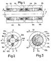
- Each of the rings (such as 2a and 2b) is mounted on the shaft 1 by means of two magnetic bearings (4a and 4'a to the ring 2 a and 4 b and 4 'b to the ring 2 b).
- the magnetic bearing shown in FIG. 2 comprises four power windings 8 and four measurement windings 10 constituted by toroids arranged coaxially in pairs.
- the bearing consists of the shaft 1 carrying the bo hoes and constituting the stator and by the ring 2.
- the magnetic bearing thus defined and represented in FIG. 2 comprises two power coils 8a and 8c arranged with their axis in the direction Y'Y along the axis of which the spacing measurement coils 10 a and 10 are disposed respectively.
- C as well as two power windings 8 b and 8 d arranged with their axis in the direction X'X perpendicular to the direction Y'Y, along the axis of which are arranged measurement windings 10 b and 10 d .
- the measurement windings 10a to 10 d deliver a current which is a function of the distance separating the measurement end 12 of the sensor from the internal surface of the ring 2.
- the power windings 8 operate by attraction of the ring 2 so that each of the measurement windings 10 controls the power winding which is opposite to it on the stator 1.
- the winding 10a determines the excitation current of the power winding 8 c while the measurement winding 10 C controls the current of 8g power winding excitation.
- the measurement winding 10 b controls the excitation current of the power winding 8 d while the measurement winding 10 d controls the excitation of the power winding 8 b .
- the excitation currents are controlled so as to maintain a fixed distance between the stator, that is to say between the measuring parts 12 of the windings 10 and the internal surface of the ring 2.
- FIG 3 there is shown a flatness roll of a measuring device according to the invention, the stator 14 is machined to form four pole pieces 15 which are wound on a pair of coils 16a and 16b and a pair of coils 17a and 17 b respectively.
- the supply of the windings keeps the ring 20 made of magnetic material relative to the stator 14 with a constant air gap.
- the strip 22 is in contact with the external surface of the ring 20 in an arc corresponding to the winding angle e of this strip.
- a traction T is exerted in the strip which thus exerts on the roller, at the level of the ring 20, radial forces of resultant F situated in the lower left quadrant of the roller.
- This force F breaks down into force F x and Fy along the axes X'X and Y'Y respectively.
- the excitation currents of the coils 16a and 16b arranged symmetrically with respect to the direction X'X for determining the compo health F x of the radial force F while the windings 17a and 17b arranged symmetrically with respect to the steering Y'Y to determine the component Fy of F.
- the magnetic attraction forces exerted by the windings wound on the pole pieces are a function of the excitation current and are directed along X'X and Y'Y respectively.
- the radial force exerted by the strip can be determined, this force F being equal to F x 2 + F y 2 .
- This force F is proportional to the traction T exerted by the strip on the ring 20 considered. Knowing the values of F for each of the rings therefore makes it possible to know the distribution of the pulls in the strip and therefore to give an image of the flatness of this strip along its width.
- the resulting force F is also of constant direction, so that it is possible to use a stator comprising only two pole pieces on which a single pair of windings is wound.
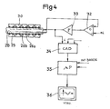
- FIG. 4 there is shown very schematically a flatness roller as shown in FIGS. 1 and 2 and comprising a fixed shaft 25 on which are mounted magnetic bearings 26 grouped in pairs each corresponding to a ring 30.
- Each of the magnetic bearings 26 consists of four power windings and four distance measurement windings arranged at 90 °.
- the shaft 25 is pierced along its axis with a cylindrical opening 28 inside which the supply wires of the various power coils and the measurement wires from the measurement coils of the various magnetic bearings 26 are passed.
- Each of the wires connected to the measurement windings delivering a current which is a function of the air gap between the stator and the rotor at the level of the coil
- the corresponding measurement ge is brought to an amplifier-comparator 32 which allows the comparison of the different measurement currents with a signal e representative of a predetermined air gap value.
- the difference between the measurement current and the signal representative of the air gap value is sent to a power amplifier 33.
- the difference signal is amplified and then sent in the form of an excitation current to the power winding controlled by the measurement winding considered.
- 4N identical sets 32-33 will therefore be used.
- the 4N excitation currents are sent to an analog-digital conversion module 34.
- the radial forces F allow the calculation of the traction in the strip, at the level of the corresponding magnetic bearing, in the mini-computer 35.
- the mini-computer 35 also provides the digital processing prior to the edition of the results in the form of a curve or of modeling polynomial parameters.
- the display of the results by the display unit 36 controlled by the computer 35 can be achieved by a screen on which the value of the traction is shown as a function of the position of the measurement point, that is to say say magnetic bearing, along the width of the strip.
- the computer can control means acting on the profile of the strip, such as a rolling mill stand, for example.
- the spacing between the successive rings 30 has a very small value and corresponds to the minimum clearance so that these rings can move independently of one another. This minimum clearance is maintained by permanent magnets mounted in the sides of the rings.
- the air gap e between the stator and the internal surface of these rings is maintained at a fixed and constant value for all of the rings, so that the system has infinite rigidity when the power windings are supplied in a desirable manner.
- the flatness roller is practically equivalent to a rigid roller whose external surface is entirely smooth. The risks of marking the strip are therefore nonexistent.
- Another advantage of the device according to the invention is to allow a direct determination of the values of the traction, from the excitation currents of the power windings, themselves determined from the signal of difference between the signal given by the measurement winding and the predetermined value of the air gap.
- the device makes it possible to eliminate the influence of the angle of winding of the strip on the roller since the result of the radial forces of this strip on the flatness roller is ultimately determined.
- This is the case in particular of the device represented in FIG. 3 where the determination of the components F x and Fy of the force F allows its quantitative determination whatever the angle of winding of the strip 22 on the outer ring of the roller .
- the device shown in FIG. 3 it is also possible to determine the total traction exerted by the strip and the angle of deflection of the strip by the roller from the ratio Fy / F X giving the tangent of this angle.
- Magnetic bearings can operate by attraction or repulsion.
- the invention applies in all cases where it is desired to measure the flatness of a stretched metal strip, continuously, the strip being scrolled or discontinuously, the strip being supported on the deflection roller .
Landscapes
- Physics & Mathematics (AREA)
- General Physics & Mathematics (AREA)
- Engineering & Computer Science (AREA)
- Mechanical Engineering (AREA)
- Force Measurement Appropriate To Specific Purposes (AREA)
- Length Measuring Devices With Unspecified Measuring Means (AREA)
- Measurement Of Length, Angles, Or The Like Using Electric Or Magnetic Means (AREA)
Priority Applications (1)
| Application Number | Priority Date | Filing Date | Title |
|---|---|---|---|
| AT83402523T ATE26017T1 (de) | 1982-12-24 | 1983-12-23 | Vorrichtung zur messung der plattheit eines unter spannung stehenden bandes. |
Applications Claiming Priority (2)
| Application Number | Priority Date | Filing Date | Title |
|---|---|---|---|
| FR8221740 | 1982-12-24 | ||
| FR8221740A FR2538537B1 (fr) | 1982-12-24 | 1982-12-24 | Dispositif de mesure de la planeite d'une bande de metal sous tension |
Publications (3)
| Publication Number | Publication Date |
|---|---|
| EP0112781A2 true EP0112781A2 (de) | 1984-07-04 |
| EP0112781A3 EP0112781A3 (en) | 1984-08-01 |
| EP0112781B1 EP0112781B1 (de) | 1987-03-18 |
Family
ID=9280493
Family Applications (1)
| Application Number | Title | Priority Date | Filing Date |
|---|---|---|---|
| EP83402523A Expired EP0112781B1 (de) | 1982-12-24 | 1983-12-23 | Vorrichtung zur Messung der Plattheit eines unter Spannung stehenden Bandes |
Country Status (5)
| Country | Link |
|---|---|
| EP (1) | EP0112781B1 (de) |
| JP (1) | JPS59120905A (de) |
| AT (1) | ATE26017T1 (de) |
| DE (1) | DE3370373D1 (de) |
| FR (1) | FR2538537B1 (de) |
Cited By (4)
| Publication number | Priority date | Publication date | Assignee | Title |
|---|---|---|---|---|
| EP0145547A1 (de) * | 1983-11-18 | 1985-06-19 | SOCIETE EUROPEENNE DE PROPULSION (S.E.P.) Société Anonyme dite: | Vorrichtung zur Messung der Longitudinalspannung in einem Materialband |
| EP0286533A1 (de) * | 1987-04-09 | 1988-10-12 | Clecim | Verfahren und Vorrichtung zum Walzen von Metallbändern oder Blechen |
| US6263716B1 (en) * | 1996-04-29 | 2001-07-24 | Tippins Incorporated | Hot strip reversing mill with a shapemetering apparatus |
| CN109870130A (zh) * | 2019-04-09 | 2019-06-11 | 中国科学技术大学 | 一种超声阵列检测物件平整度的测量方法与装置 |
Families Citing this family (2)
| Publication number | Priority date | Publication date | Assignee | Title |
|---|---|---|---|---|
| CN106066152B (zh) * | 2016-06-08 | 2018-07-03 | 燕山大学 | 一种热轧接触式板形检测辊主体结构 |
| DE102020210970A1 (de) * | 2020-08-31 | 2022-03-03 | Sms Group Gmbh | Planheitsmessvorrichtung, Warmwalzanlage und Verfahren zum Betreiben einer Planheitsmessvorrichtung |
Family Cites Families (3)
| Publication number | Priority date | Publication date | Assignee | Title |
|---|---|---|---|---|
| US3890834A (en) * | 1972-09-11 | 1975-06-24 | Asea Ab | Force or tension measuring means |
| US4245869A (en) * | 1978-08-07 | 1981-01-20 | Padana Ag | Magnetic bearings |
| DE2848638C2 (de) * | 1978-11-09 | 1983-11-03 | Fried. Krupp Gmbh, 4300 Essen | Meßrolle zur Erfassung der Spannungsverteilung in einem laufenden Band |
-
1982
- 1982-12-24 FR FR8221740A patent/FR2538537B1/fr not_active Expired
-
1983
- 1983-12-01 JP JP58227780A patent/JPS59120905A/ja active Pending
- 1983-12-23 EP EP83402523A patent/EP0112781B1/de not_active Expired
- 1983-12-23 DE DE8383402523T patent/DE3370373D1/de not_active Expired
- 1983-12-23 AT AT83402523T patent/ATE26017T1/de not_active IP Right Cessation
Cited By (5)
| Publication number | Priority date | Publication date | Assignee | Title |
|---|---|---|---|---|
| EP0145547A1 (de) * | 1983-11-18 | 1985-06-19 | SOCIETE EUROPEENNE DE PROPULSION (S.E.P.) Société Anonyme dite: | Vorrichtung zur Messung der Longitudinalspannung in einem Materialband |
| EP0286533A1 (de) * | 1987-04-09 | 1988-10-12 | Clecim | Verfahren und Vorrichtung zum Walzen von Metallbändern oder Blechen |
| FR2613641A1 (fr) * | 1987-04-09 | 1988-10-14 | Clecim Sa | Procede et installation de laminage d'un produit sous forme de bande, plus specialement une tole metallique ou un feuillard |
| US6263716B1 (en) * | 1996-04-29 | 2001-07-24 | Tippins Incorporated | Hot strip reversing mill with a shapemetering apparatus |
| CN109870130A (zh) * | 2019-04-09 | 2019-06-11 | 中国科学技术大学 | 一种超声阵列检测物件平整度的测量方法与装置 |
Also Published As
| Publication number | Publication date |
|---|---|
| JPS59120905A (ja) | 1984-07-12 |
| FR2538537B1 (fr) | 1986-05-23 |
| FR2538537A1 (fr) | 1984-06-29 |
| EP0112781A3 (en) | 1984-08-01 |
| ATE26017T1 (de) | 1987-04-15 |
| DE3370373D1 (en) | 1987-04-23 |
| EP0112781B1 (de) | 1987-03-18 |
Similar Documents
| Publication | Publication Date | Title |
|---|---|---|
| EP0028191B1 (de) | Vorrichtung zum Feststellen von Planheitsfehlern in einem sich unter Spannung bewegenden Band | |
| EP0112781B1 (de) | Vorrichtung zur Messung der Plattheit eines unter Spannung stehenden Bandes | |
| FR2877862A1 (fr) | Procede de detection des vibrations d'une cage de laminoir | |
| CH387965A (fr) | Dispositif pour mesurer la vitesse d'oscillation ou de rotation d'une partie d'une pièce rotative qui peut osciller ou tourner par rapport au reste de cette pièce | |
| EP3194917B1 (de) | Induktiver rotationssensor mit verbesserter precision | |
| EP0286533B1 (de) | Verfahren und Vorrichtung zum Walzen von Metallbändern oder Blechen | |
| FR2488819A1 (fr) | Appareil a redresser les tubes d'acier et analogues | |
| FR2808872A1 (fr) | Capteurs inductifs en etoile pour la detection de la position radiale d'un rotor dans un stator | |
| FR2587107A1 (fr) | Appareil de controle de rectitude de tubes | |
| FR2542124A1 (fr) | Systeme de mesure de la rectitude des barres de combustible nucleaire | |
| EP0622610A1 (de) | Verfahren und Anordnung zum Eichen der Dickenmessanordnung des Querprofils eines flächigen Gutes | |
| EP0615608B1 (de) | Messroller zur Planleitsmessung eines fortlaufend produzierten Bandes | |
| EP0030889B1 (de) | Verfahren und Vorrichtung zum zerstörungsfreien Prüfen von Punktschweissungen | |
| EP0225827B1 (de) | Drehender Walzenring | |
| CA1287906C (fr) | Dispositif de mesure des defauts de planeite d'une bande | |
| FR2548930A1 (fr) | Procede et appareillage pour commander la correction de laminage dans un laminoir | |
| EP0145547B1 (de) | Vorrichtung zur Messung der Longitudinalspannung in einem Materialband | |
| FR2771809A1 (fr) | Appareil de mesure de la planeite d'une bande au defile | |
| EP0270442B1 (de) | Walze zum Kontrollieren der Kontur eines sich bewegenden Streifens | |
| FR2562655A1 (fr) | Dispositif de mesure destine a mesurer la fente entre deux cylindres ou rouleaux et procede pour l'execution de la mesure | |
| FR2630418A1 (fr) | Dispositif d'entrainement par traction d'un materiau long a section sensiblement constante | |
| CH430343A (fr) | Dispositif de maintien radial sans frottement mécanique d'un arbre rotatif dans une pièce fixe solidaire d'un bâti | |
| EP0162152B1 (de) | Steuerung, welche eine Messung der Zugkraft in einer Schleife zwischen zwei aufeinanderfolgenden Walzenständern einer Warmbandstrasse benützt | |
| CH503338A (fr) | Dispositif d'identification de pièces de monnaie | |
| FR2780502A1 (fr) | Procede et dispositif de mesure de planeite |
Legal Events
| Date | Code | Title | Description |
|---|---|---|---|
| PUAI | Public reference made under article 153(3) epc to a published international application that has entered the european phase |
Free format text: ORIGINAL CODE: 0009012 |
|
| PUAL | Search report despatched |
Free format text: ORIGINAL CODE: 0009013 |
|
| AK | Designated contracting states |
Designated state(s): AT BE CH DE GB IT LI LU NL SE |
|
| AK | Designated contracting states |
Designated state(s): AT BE CH DE GB IT LI LU NL SE |
|
| 17P | Request for examination filed |
Effective date: 19840813 |
|
| GRAA | (expected) grant |
Free format text: ORIGINAL CODE: 0009210 |
|
| AK | Designated contracting states |
Kind code of ref document: B1 Designated state(s): AT BE CH DE GB IT LI LU NL SE |
|
| PG25 | Lapsed in a contracting state [announced via postgrant information from national office to epo] |
Ref country code: SE Effective date: 19870318 Ref country code: NL Effective date: 19870318 Ref country code: IT Free format text: LAPSE BECAUSE OF FAILURE TO SUBMIT A TRANSLATION OF THE DESCRIPTION OR TO PAY THE FEE WITHIN THE PRESCRIBED TIME-LIMIT;WARNING: LAPSES OF ITALIAN PATENTS WITH EFFECTIVE DATE BEFORE 2007 MAY HAVE OCCURRED AT ANY TIME BEFORE 2007. THE CORRECT EFFECTIVE DATE MAY BE DIFFERENT FROM THE ONE RECORDED. Effective date: 19870318 Ref country code: AT Effective date: 19870318 |
|
| REF | Corresponds to: |
Ref document number: 26017 Country of ref document: AT Date of ref document: 19870415 Kind code of ref document: T |
|
| REF | Corresponds to: |
Ref document number: 3370373 Country of ref document: DE Date of ref document: 19870423 |
|
| NLV1 | Nl: lapsed or annulled due to failure to fulfill the requirements of art. 29p and 29m of the patents act | ||
| PG25 | Lapsed in a contracting state [announced via postgrant information from national office to epo] |
Ref country code: LU Free format text: LAPSE BECAUSE OF NON-PAYMENT OF DUE FEES Effective date: 19871231 Ref country code: LI Effective date: 19871231 Ref country code: CH Effective date: 19871231 Ref country code: BE Effective date: 19871231 |
|
| PLBE | No opposition filed within time limit |
Free format text: ORIGINAL CODE: 0009261 |
|
| STAA | Information on the status of an ep patent application or granted ep patent |
Free format text: STATUS: NO OPPOSITION FILED WITHIN TIME LIMIT |
|
| 26N | No opposition filed | ||
| BERE | Be: lapsed |
Owner name: CLECIM Effective date: 19871231 |
|
| REG | Reference to a national code |
Ref country code: CH Ref legal event code: PL |
|
| PGFP | Annual fee paid to national office [announced via postgrant information from national office to epo] |
Ref country code: GB Payment date: 19901212 Year of fee payment: 8 |
|
| PGFP | Annual fee paid to national office [announced via postgrant information from national office to epo] |
Ref country code: DE Payment date: 19910123 Year of fee payment: 8 |
|
| PG25 | Lapsed in a contracting state [announced via postgrant information from national office to epo] |
Ref country code: GB Effective date: 19911223 |
|
| GBPC | Gb: european patent ceased through non-payment of renewal fee | ||
| PG25 | Lapsed in a contracting state [announced via postgrant information from national office to epo] |
Ref country code: DE Effective date: 19920901 |