EP0112923B1 - Condensateur a double couche electrique - Google Patents
Condensateur a double couche electrique Download PDFInfo
- Publication number
- EP0112923B1 EP0112923B1 EP83902122A EP83902122A EP0112923B1 EP 0112923 B1 EP0112923 B1 EP 0112923B1 EP 83902122 A EP83902122 A EP 83902122A EP 83902122 A EP83902122 A EP 83902122A EP 0112923 B1 EP0112923 B1 EP 0112923B1
- Authority
- EP
- European Patent Office
- Prior art keywords
- capacitor
- carbon fibers
- conductive
- electrode
- activated carbon
- Prior art date
- Legal status (The legal status is an assumption and is not a legal conclusion. Google has not performed a legal analysis and makes no representation as to the accuracy of the status listed.)
- Expired
Links
- 239000003990 capacitor Substances 0.000 title claims abstract description 138
- OKTJSMMVPCPJKN-UHFFFAOYSA-N Carbon Chemical compound [C] OKTJSMMVPCPJKN-UHFFFAOYSA-N 0.000 claims abstract description 188
- 239000003792 electrolyte Substances 0.000 claims abstract description 50
- 229920000049 Carbon (fiber) Polymers 0.000 claims description 68
- 229910052751 metal Inorganic materials 0.000 claims description 51
- 239000002184 metal Substances 0.000 claims description 51
- 239000011148 porous material Substances 0.000 claims description 47
- 239000004744 fabric Substances 0.000 claims description 30
- 239000004917 carbon fiber Substances 0.000 claims description 28
- XTHFKEDIFFGKHM-UHFFFAOYSA-N Dimethoxyethane Chemical compound COCCOC XTHFKEDIFFGKHM-UHFFFAOYSA-N 0.000 claims description 22
- 239000003795 chemical substances by application Substances 0.000 claims description 16
- XAGFODPZIPBFFR-UHFFFAOYSA-N aluminium Chemical compound [Al] XAGFODPZIPBFFR-UHFFFAOYSA-N 0.000 claims description 15
- 229910052782 aluminium Inorganic materials 0.000 claims description 14
- 230000004913 activation Effects 0.000 claims description 12
- 239000000463 material Substances 0.000 claims description 12
- 239000011133 lead Substances 0.000 claims description 10
- 239000003973 paint Substances 0.000 claims description 10
- 238000007750 plasma spraying Methods 0.000 claims description 10
- ISWSIDIOOBJBQZ-UHFFFAOYSA-N Phenol Chemical compound OC1=CC=CC=C1 ISWSIDIOOBJBQZ-UHFFFAOYSA-N 0.000 claims description 9
- 229920003986 novolac Polymers 0.000 claims description 9
- 239000003054 catalyst Substances 0.000 claims description 7
- 239000011888 foil Substances 0.000 claims description 7
- 238000005507 spraying Methods 0.000 claims description 6
- RYGMFSIKBFXOCR-UHFFFAOYSA-N Copper Chemical compound [Cu] RYGMFSIKBFXOCR-UHFFFAOYSA-N 0.000 claims description 5
- HCHKCACWOHOZIP-UHFFFAOYSA-N Zinc Chemical compound [Zn] HCHKCACWOHOZIP-UHFFFAOYSA-N 0.000 claims description 5
- 229910052802 copper Inorganic materials 0.000 claims description 5
- 239000010949 copper Substances 0.000 claims description 5
- 150000003839 salts Chemical class 0.000 claims description 5
- 229910052725 zinc Inorganic materials 0.000 claims description 5
- 239000011701 zinc Substances 0.000 claims description 5
- PXHVJJICTQNCMI-UHFFFAOYSA-N Nickel Chemical compound [Ni] PXHVJJICTQNCMI-UHFFFAOYSA-N 0.000 claims description 4
- KJTLSVCANCCWHF-UHFFFAOYSA-N Ruthenium Chemical compound [Ru] KJTLSVCANCCWHF-UHFFFAOYSA-N 0.000 claims description 3
- ATJFFYVFTNAWJD-UHFFFAOYSA-N Tin Chemical compound [Sn] ATJFFYVFTNAWJD-UHFFFAOYSA-N 0.000 claims description 3
- RTAQQCXQSZGOHL-UHFFFAOYSA-N Titanium Chemical compound [Ti] RTAQQCXQSZGOHL-UHFFFAOYSA-N 0.000 claims description 3
- 238000003763 carbonization Methods 0.000 claims description 3
- 229910052707 ruthenium Inorganic materials 0.000 claims description 3
- 229910052715 tantalum Inorganic materials 0.000 claims description 3
- GUVRBAGPIYLISA-UHFFFAOYSA-N tantalum atom Chemical compound [Ta] GUVRBAGPIYLISA-UHFFFAOYSA-N 0.000 claims description 3
- 229910052718 tin Inorganic materials 0.000 claims description 3
- 239000011135 tin Substances 0.000 claims description 3
- 229910052719 titanium Inorganic materials 0.000 claims description 3
- 239000010936 titanium Substances 0.000 claims description 3
- OYPRJOBELJOOCE-UHFFFAOYSA-N Calcium Chemical compound [Ca] OYPRJOBELJOOCE-UHFFFAOYSA-N 0.000 claims description 2
- DGAQECJNVWCQMB-PUAWFVPOSA-M Ilexoside XXIX Chemical compound C[C@@H]1CC[C@@]2(CC[C@@]3(C(=CC[C@H]4[C@]3(CC[C@@H]5[C@@]4(CC[C@@H](C5(C)C)OS(=O)(=O)[O-])C)C)[C@@H]2[C@]1(C)O)C)C(=O)O[C@H]6[C@@H]([C@H]([C@@H]([C@H](O6)CO)O)O)O.[Na+] DGAQECJNVWCQMB-PUAWFVPOSA-M 0.000 claims description 2
- WHXSMMKQMYFTQS-UHFFFAOYSA-N Lithium Chemical compound [Li] WHXSMMKQMYFTQS-UHFFFAOYSA-N 0.000 claims description 2
- FYYHWMGAXLPEAU-UHFFFAOYSA-N Magnesium Chemical compound [Mg] FYYHWMGAXLPEAU-UHFFFAOYSA-N 0.000 claims description 2
- ZLMJMSJWJFRBEC-UHFFFAOYSA-N Potassium Chemical compound [K] ZLMJMSJWJFRBEC-UHFFFAOYSA-N 0.000 claims description 2
- 229910052791 calcium Inorganic materials 0.000 claims description 2
- 239000011575 calcium Substances 0.000 claims description 2
- 229910052738 indium Inorganic materials 0.000 claims description 2
- APFVFJFRJDLVQX-UHFFFAOYSA-N indium atom Chemical compound [In] APFVFJFRJDLVQX-UHFFFAOYSA-N 0.000 claims description 2
- 150000002500 ions Chemical class 0.000 claims description 2
- 229910052741 iridium Inorganic materials 0.000 claims description 2
- GKOZUEZYRPOHIO-UHFFFAOYSA-N iridium atom Chemical compound [Ir] GKOZUEZYRPOHIO-UHFFFAOYSA-N 0.000 claims description 2
- 229910052744 lithium Inorganic materials 0.000 claims description 2
- 229910052749 magnesium Inorganic materials 0.000 claims description 2
- 239000011777 magnesium Substances 0.000 claims description 2
- 229910052759 nickel Inorganic materials 0.000 claims description 2
- 229910052762 osmium Inorganic materials 0.000 claims description 2
- SYQBFIAQOQZEGI-UHFFFAOYSA-N osmium atom Chemical compound [Os] SYQBFIAQOQZEGI-UHFFFAOYSA-N 0.000 claims description 2
- 229910052700 potassium Inorganic materials 0.000 claims description 2
- 239000011591 potassium Substances 0.000 claims description 2
- 229910052708 sodium Inorganic materials 0.000 claims description 2
- 239000011734 sodium Substances 0.000 claims description 2
- BASFCYQUMIYNBI-UHFFFAOYSA-N platinum Chemical compound [Pt] BASFCYQUMIYNBI-UHFFFAOYSA-N 0.000 claims 2
- 229910000314 transition metal oxide Inorganic materials 0.000 claims 2
- NPXOKRUENSOPAO-UHFFFAOYSA-N Raney nickel Chemical compound [Al].[Ni] NPXOKRUENSOPAO-UHFFFAOYSA-N 0.000 claims 1
- 230000003213 activating effect Effects 0.000 claims 1
- XLYOFNOQVPJJNP-UHFFFAOYSA-M hydroxide Chemical compound [OH-] XLYOFNOQVPJJNP-UHFFFAOYSA-M 0.000 claims 1
- 238000003475 lamination Methods 0.000 claims 1
- 229910052697 platinum Inorganic materials 0.000 claims 1
- VNWKTOKETHGBQD-UHFFFAOYSA-N methane Chemical class C VNWKTOKETHGBQD-UHFFFAOYSA-N 0.000 abstract description 40
- 229910052799 carbon Inorganic materials 0.000 abstract description 8
- 239000011203 carbon fibre reinforced carbon Substances 0.000 abstract 2
- 239000010410 layer Substances 0.000 description 58
- 238000000034 method Methods 0.000 description 28
- RUOJZAUFBMNUDX-UHFFFAOYSA-N propylene carbonate Chemical compound CC1COC(=O)O1 RUOJZAUFBMNUDX-UHFFFAOYSA-N 0.000 description 16
- -1 acryl Chemical group 0.000 description 15
- 239000000835 fiber Substances 0.000 description 13
- 238000001994 activation Methods 0.000 description 12
- 239000007921 spray Substances 0.000 description 11
- 238000004519 manufacturing process Methods 0.000 description 10
- 239000000843 powder Substances 0.000 description 10
- 239000004743 Polypropylene Substances 0.000 description 8
- 229920001155 polypropylene Polymers 0.000 description 8
- 239000002904 solvent Substances 0.000 description 8
- 229920005989 resin Polymers 0.000 description 7
- 239000011347 resin Substances 0.000 description 7
- ZMXDDKWLCZADIW-UHFFFAOYSA-N N,N-Dimethylformamide Chemical compound CN(C)C=O ZMXDDKWLCZADIW-UHFFFAOYSA-N 0.000 description 6
- 239000007864 aqueous solution Substances 0.000 description 6
- 230000000694 effects Effects 0.000 description 6
- WGHUNMFFLAMBJD-UHFFFAOYSA-M tetraethylazanium;perchlorate Chemical compound [O-]Cl(=O)(=O)=O.CC[N+](CC)(CC)CC WGHUNMFFLAMBJD-UHFFFAOYSA-M 0.000 description 6
- 238000009826 distribution Methods 0.000 description 5
- 229920001971 elastomer Polymers 0.000 description 5
- 238000009413 insulation Methods 0.000 description 5
- 239000007788 liquid Substances 0.000 description 5
- 229910021645 metal ion Inorganic materials 0.000 description 5
- 230000035699 permeability Effects 0.000 description 5
- 239000000126 substance Substances 0.000 description 5
- XLYOFNOQVPJJNP-UHFFFAOYSA-N water Substances O XLYOFNOQVPJJNP-UHFFFAOYSA-N 0.000 description 5
- WYURNTSHIVDZCO-UHFFFAOYSA-N Tetrahydrofuran Chemical compound C1CCOC1 WYURNTSHIVDZCO-UHFFFAOYSA-N 0.000 description 4
- 239000011230 binding agent Substances 0.000 description 4
- 238000010276 construction Methods 0.000 description 4
- 230000014759 maintenance of location Effects 0.000 description 4
- 229910001925 ruthenium oxide Inorganic materials 0.000 description 4
- YBCAZPLXEGKKFM-UHFFFAOYSA-K ruthenium(iii) chloride Chemical compound [Cl-].[Cl-].[Cl-].[Ru+3] YBCAZPLXEGKKFM-UHFFFAOYSA-K 0.000 description 4
- WOCIAKWEIIZHES-UHFFFAOYSA-N ruthenium(iv) oxide Chemical compound O=[Ru]=O WOCIAKWEIIZHES-UHFFFAOYSA-N 0.000 description 4
- ZCWKIFAQRXNZCH-UHFFFAOYSA-M tetramethylazanium;perchlorate Chemical compound C[N+](C)(C)C.[O-]Cl(=O)(=O)=O ZCWKIFAQRXNZCH-UHFFFAOYSA-M 0.000 description 4
- XOLBLPGZBRYERU-UHFFFAOYSA-N tin dioxide Chemical compound O=[Sn]=O XOLBLPGZBRYERU-UHFFFAOYSA-N 0.000 description 4
- 229910001887 tin oxide Inorganic materials 0.000 description 4
- LYCAIKOWRPUZTN-UHFFFAOYSA-N Ethylene glycol Chemical compound OCCO LYCAIKOWRPUZTN-UHFFFAOYSA-N 0.000 description 3
- BQCADISMDOOEFD-UHFFFAOYSA-N Silver Chemical compound [Ag] BQCADISMDOOEFD-UHFFFAOYSA-N 0.000 description 3
- HEMHJVSKTPXQMS-UHFFFAOYSA-M Sodium hydroxide Chemical compound [OH-].[Na+] HEMHJVSKTPXQMS-UHFFFAOYSA-M 0.000 description 3
- 230000015572 biosynthetic process Effects 0.000 description 3
- 239000011248 coating agent Substances 0.000 description 3
- 238000000576 coating method Methods 0.000 description 3
- 230000007423 decrease Effects 0.000 description 3
- 238000007598 dipping method Methods 0.000 description 3
- 239000008187 granular material Substances 0.000 description 3
- 238000004080 punching Methods 0.000 description 3
- 229910052709 silver Inorganic materials 0.000 description 3
- 239000004332 silver Substances 0.000 description 3
- 238000002791 soaking Methods 0.000 description 3
- 239000000243 solution Substances 0.000 description 3
- 125000006850 spacer group Chemical group 0.000 description 3
- 238000001771 vacuum deposition Methods 0.000 description 3
- IJGRMHOSHXDMSA-UHFFFAOYSA-N Atomic nitrogen Chemical compound N#N IJGRMHOSHXDMSA-UHFFFAOYSA-N 0.000 description 2
- 235000013162 Cocos nucifera Nutrition 0.000 description 2
- 244000060011 Cocos nucifera Species 0.000 description 2
- LCGLNKUTAGEVQW-UHFFFAOYSA-N Dimethyl ether Chemical compound COC LCGLNKUTAGEVQW-UHFFFAOYSA-N 0.000 description 2
- 229920000297 Rayon Polymers 0.000 description 2
- QAOWNCQODCNURD-UHFFFAOYSA-N Sulfuric acid Chemical compound OS(O)(=O)=O QAOWNCQODCNURD-UHFFFAOYSA-N 0.000 description 2
- 230000015556 catabolic process Effects 0.000 description 2
- 230000008859 change Effects 0.000 description 2
- 238000005520 cutting process Methods 0.000 description 2
- 238000000151 deposition Methods 0.000 description 2
- 238000010586 diagram Methods 0.000 description 2
- 238000009792 diffusion process Methods 0.000 description 2
- 238000005516 engineering process Methods 0.000 description 2
- 150000004679 hydroxides Chemical class 0.000 description 2
- 238000005470 impregnation Methods 0.000 description 2
- 150000002739 metals Chemical class 0.000 description 2
- 239000011259 mixed solution Substances 0.000 description 2
- 238000002156 mixing Methods 0.000 description 2
- 239000000203 mixture Substances 0.000 description 2
- 230000008569 process Effects 0.000 description 2
- 239000002964 rayon Substances 0.000 description 2
- 238000005096 rolling process Methods 0.000 description 2
- 238000007789 sealing Methods 0.000 description 2
- 238000004544 sputter deposition Methods 0.000 description 2
- 229910001220 stainless steel Inorganic materials 0.000 description 2
- 239000010935 stainless steel Substances 0.000 description 2
- 239000000758 substrate Substances 0.000 description 2
- YLQBMQCUIZJEEH-UHFFFAOYSA-N tetrahydrofuran Natural products C=1C=COC=1 YLQBMQCUIZJEEH-UHFFFAOYSA-N 0.000 description 2
- 238000005979 thermal decomposition reaction Methods 0.000 description 2
- 238000004804 winding Methods 0.000 description 2
- JIAARYAFYJHUJI-UHFFFAOYSA-L zinc dichloride Chemical compound [Cl-].[Cl-].[Zn+2] JIAARYAFYJHUJI-UHFFFAOYSA-L 0.000 description 2
- GDDNTTHUKVNJRA-UHFFFAOYSA-N 3-bromo-3,3-difluoroprop-1-ene Chemical compound FC(F)(Br)C=C GDDNTTHUKVNJRA-UHFFFAOYSA-N 0.000 description 1
- 239000004215 Carbon black (E152) Substances 0.000 description 1
- 229920002134 Carboxymethyl cellulose Polymers 0.000 description 1
- 239000004593 Epoxy Substances 0.000 description 1
- LFQSCWFLJHTTHZ-UHFFFAOYSA-N Ethanol Chemical compound CCO LFQSCWFLJHTTHZ-UHFFFAOYSA-N 0.000 description 1
- YCKRFDGAMUMZLT-UHFFFAOYSA-N Fluorine atom Chemical compound [F] YCKRFDGAMUMZLT-UHFFFAOYSA-N 0.000 description 1
- 229910019142 PO4 Inorganic materials 0.000 description 1
- 229920006282 Phenolic fiber Polymers 0.000 description 1
- 229910052784 alkaline earth metal Inorganic materials 0.000 description 1
- 239000004411 aluminium Substances 0.000 description 1
- 125000003277 amino group Chemical group 0.000 description 1
- 239000012298 atmosphere Substances 0.000 description 1
- 238000005422 blasting Methods 0.000 description 1
- 238000009835 boiling Methods 0.000 description 1
- 125000002915 carbonyl group Chemical group [*:2]C([*:1])=O 0.000 description 1
- 239000001768 carboxy methyl cellulose Substances 0.000 description 1
- 235000010948 carboxy methyl cellulose Nutrition 0.000 description 1
- 239000008112 carboxymethyl-cellulose Substances 0.000 description 1
- 229940105329 carboxymethylcellulose Drugs 0.000 description 1
- 239000000919 ceramic Substances 0.000 description 1
- 238000006243 chemical reaction Methods 0.000 description 1
- 150000001805 chlorine compounds Chemical class 0.000 description 1
- 239000000084 colloidal system Substances 0.000 description 1
- 239000004020 conductor Substances 0.000 description 1
- 125000004122 cyclic group Chemical group 0.000 description 1
- 230000003247 decreasing effect Effects 0.000 description 1
- 230000001419 dependent effect Effects 0.000 description 1
- 230000008021 deposition Effects 0.000 description 1
- 238000011161 development Methods 0.000 description 1
- 230000018109 developmental process Effects 0.000 description 1
- 239000000806 elastomer Substances 0.000 description 1
- 230000005684 electric field Effects 0.000 description 1
- 238000009713 electroplating Methods 0.000 description 1
- 239000003822 epoxy resin Substances 0.000 description 1
- 125000001033 ether group Chemical group 0.000 description 1
- 229940093476 ethylene glycol Drugs 0.000 description 1
- 229910052731 fluorine Inorganic materials 0.000 description 1
- 239000011737 fluorine Substances 0.000 description 1
- 239000007789 gas Substances 0.000 description 1
- 229910002804 graphite Inorganic materials 0.000 description 1
- 239000010439 graphite Substances 0.000 description 1
- 230000012447 hatching Effects 0.000 description 1
- 229930195733 hydrocarbon Natural products 0.000 description 1
- 150000002430 hydrocarbons Chemical class 0.000 description 1
- 229910003437 indium oxide Inorganic materials 0.000 description 1
- PJXISJQVUVHSOJ-UHFFFAOYSA-N indium(iii) oxide Chemical compound [O-2].[O-2].[O-2].[In+3].[In+3] PJXISJQVUVHSOJ-UHFFFAOYSA-N 0.000 description 1
- 238000010030 laminating Methods 0.000 description 1
- WABPQHHGFIMREM-UHFFFAOYSA-N lead(0) Chemical compound [Pb] WABPQHHGFIMREM-UHFFFAOYSA-N 0.000 description 1
- 238000005259 measurement Methods 0.000 description 1
- QSHDDOUJBYECFT-UHFFFAOYSA-N mercury Chemical compound [Hg] QSHDDOUJBYECFT-UHFFFAOYSA-N 0.000 description 1
- 229910052753 mercury Inorganic materials 0.000 description 1
- 229920000609 methyl cellulose Polymers 0.000 description 1
- 125000002496 methyl group Chemical group [H]C([H])([H])* 0.000 description 1
- 239000001923 methylcellulose Substances 0.000 description 1
- 235000010981 methylcellulose Nutrition 0.000 description 1
- 238000004377 microelectronic Methods 0.000 description 1
- 239000012046 mixed solvent Substances 0.000 description 1
- 150000002823 nitrates Chemical class 0.000 description 1
- 229910052757 nitrogen Inorganic materials 0.000 description 1
- 238000010422 painting Methods 0.000 description 1
- 239000005011 phenolic resin Substances 0.000 description 1
- 235000021317 phosphate Nutrition 0.000 description 1
- 150000003013 phosphoric acid derivatives Chemical class 0.000 description 1
- 229920000647 polyepoxide Polymers 0.000 description 1
- 230000000717 retained effect Effects 0.000 description 1
- 238000007788 roughening Methods 0.000 description 1
- 150000003303 ruthenium Chemical class 0.000 description 1
- 229920002050 silicone resin Polymers 0.000 description 1
- 239000002356 single layer Substances 0.000 description 1
- 229910000679 solder Inorganic materials 0.000 description 1
- 238000005728 strengthening Methods 0.000 description 1
- 230000007847 structural defect Effects 0.000 description 1
- 238000007740 vapor deposition Methods 0.000 description 1
- 239000011592 zinc chloride Substances 0.000 description 1
- 235000005074 zinc chloride Nutrition 0.000 description 1
Images






Classifications
-
- H—ELECTRICITY
- H01—ELECTRIC ELEMENTS
- H01G—CAPACITORS; CAPACITORS, RECTIFIERS, DETECTORS, SWITCHING DEVICES, LIGHT-SENSITIVE OR TEMPERATURE-SENSITIVE DEVICES OF THE ELECTROLYTIC TYPE
- H01G11/00—Hybrid capacitors, i.e. capacitors having different positive and negative electrodes; Electric double-layer [EDL] capacitors; Processes for the manufacture thereof or of parts thereof
- H01G11/22—Electrodes
- H01G11/26—Electrodes characterised by their structure, e.g. multi-layered, porosity or surface features
- H01G11/28—Electrodes characterised by their structure, e.g. multi-layered, porosity or surface features arranged or disposed on a current collector; Layers or phases between electrodes and current collectors, e.g. adhesives
-
- H—ELECTRICITY
- H01—ELECTRIC ELEMENTS
- H01G—CAPACITORS; CAPACITORS, RECTIFIERS, DETECTORS, SWITCHING DEVICES, LIGHT-SENSITIVE OR TEMPERATURE-SENSITIVE DEVICES OF THE ELECTROLYTIC TYPE
- H01G11/00—Hybrid capacitors, i.e. capacitors having different positive and negative electrodes; Electric double-layer [EDL] capacitors; Processes for the manufacture thereof or of parts thereof
- H01G11/22—Electrodes
- H01G11/30—Electrodes characterised by their material
- H01G11/32—Carbon-based
- H01G11/38—Carbon pastes or blends; Binders or additives therein
-
- H—ELECTRICITY
- H01—ELECTRIC ELEMENTS
- H01G—CAPACITORS; CAPACITORS, RECTIFIERS, DETECTORS, SWITCHING DEVICES, LIGHT-SENSITIVE OR TEMPERATURE-SENSITIVE DEVICES OF THE ELECTROLYTIC TYPE
- H01G11/00—Hybrid capacitors, i.e. capacitors having different positive and negative electrodes; Electric double-layer [EDL] capacitors; Processes for the manufacture thereof or of parts thereof
- H01G11/22—Electrodes
- H01G11/30—Electrodes characterised by their material
- H01G11/32—Carbon-based
- H01G11/40—Fibres
-
- H—ELECTRICITY
- H01—ELECTRIC ELEMENTS
- H01G—CAPACITORS; CAPACITORS, RECTIFIERS, DETECTORS, SWITCHING DEVICES, LIGHT-SENSITIVE OR TEMPERATURE-SENSITIVE DEVICES OF THE ELECTROLYTIC TYPE
- H01G11/00—Hybrid capacitors, i.e. capacitors having different positive and negative electrodes; Electric double-layer [EDL] capacitors; Processes for the manufacture thereof or of parts thereof
- H01G11/22—Electrodes
- H01G11/24—Electrodes characterised by structural features of the materials making up or comprised in the electrodes, e.g. form, surface area or porosity; characterised by the structural features of powders or particles used therefor
-
- H—ELECTRICITY
- H01—ELECTRIC ELEMENTS
- H01G—CAPACITORS; CAPACITORS, RECTIFIERS, DETECTORS, SWITCHING DEVICES, LIGHT-SENSITIVE OR TEMPERATURE-SENSITIVE DEVICES OF THE ELECTROLYTIC TYPE
- H01G11/00—Hybrid capacitors, i.e. capacitors having different positive and negative electrodes; Electric double-layer [EDL] capacitors; Processes for the manufacture thereof or of parts thereof
- H01G11/22—Electrodes
- H01G11/30—Electrodes characterised by their material
- H01G11/46—Metal oxides
-
- Y—GENERAL TAGGING OF NEW TECHNOLOGICAL DEVELOPMENTS; GENERAL TAGGING OF CROSS-SECTIONAL TECHNOLOGIES SPANNING OVER SEVERAL SECTIONS OF THE IPC; TECHNICAL SUBJECTS COVERED BY FORMER USPC CROSS-REFERENCE ART COLLECTIONS [XRACs] AND DIGESTS
- Y02—TECHNOLOGIES OR APPLICATIONS FOR MITIGATION OR ADAPTATION AGAINST CLIMATE CHANGE
- Y02E—REDUCTION OF GREENHOUSE GAS [GHG] EMISSIONS, RELATED TO ENERGY GENERATION, TRANSMISSION OR DISTRIBUTION
- Y02E60/00—Enabling technologies; Technologies with a potential or indirect contribution to GHG emissions mitigation
- Y02E60/13—Energy storage using capacitors
Definitions
- This invention relates to a capacitor having a double layer of electric charges, as stated in the precharacterizing portion of claim 1.
- a capacitor having a double layer of electric charges comprises a polarizable electrode unit constituted by an activated charcoal layer 1 and a collector electrode 2 for that layer, and a separator 3 soaked with an electrolyte arranged between a pair of polarizable electrodes.
- capacitors of this kind have belonged to the following two types.
- fist type expanded metal or punching metal worked from aluminum sheet is used as a collector body, a paste containing activated charcoal powder as main component and a binder of fluorine resin or the like as a polarizable electrode 5 is coated to be held on a surface of the collector 4 by rolling rollers 7, and a pair of collectors 4 and the polarizable electrode 5 with a separator 8 inbetween are wound up and electrolyte is injected thereto.
- Fig. 4 shows the sectional structure of the electric capacitor of this system
- Fig. 5 is an enlarged view of a part of Fig. 4.
- 10 are electrode leads, 11 is an outside face, 12 is a rubber sealing cap.
- the second capacitor type has a structure as shown in Fig. 6.
- a conductive elastomer 13, an insulating ring 14, separator 15 and a viscous mixture 16 of activated charcoal powder and an electrolyte are combined as shown in Fig. 6.
- the capacitor has a disk type outside view as shown in Fig. 7.
- the bonding force between the metal collectors 4 and the polarizable electrode 5 made of activated charcoal is weak.
- Such tendencies are observed as that the polarizable electrodes 5 drop off and peel off the collectors 4 or the bonding force between these becomes weak during use because of strain by the winding up.
- the internal resistance of the electric double layer capacitor gradually increases so that the capacitance gradually decreases.
- the polarizable electrode 5 consisting of the activated charcoal powder and the binder are rolled onto the collectors 4, its coating efficiency is bad, and scattering of capacitance due to non-uniform coating and rolling of the polarizable electrodes 5 is given as the point to be improved.
- needs of known microelectronics, for instance flat plate type structure has been difficult to realize.
- the breakdown voltage per unit cell becomes 0.8 V in this capacitor type, and it does not fulfil the demand of high breakdown voltage.
- a capacitor was devised, characterized in which two sheets of carbon fibre are used as polarizable electrodes, and they are wound up in a roll type with a separator inbetween. A step of about 1 mm is made on the opposing electrode only at the edge face and the metal layer is formed by spray method on both end faces to form collectors and lead terminals simultaneously. Though forming of the end face electrodes becomes easy in the capacitor of this type, the fundamental structure is the same as in the case of the conventional first type, and obtaining of a further small type capacitor structure is difficult.
- This invention provides a capacitor having a double layer of electric charges, which is formed at an interface between a polarizable electrode and an electrolyte.
- a pair of polarizable electrodes with said electrolyte inbetween consisting of carbon fibers or activated carbon fibers or the like is provided and a conductive electrode is formed on the outer side of each of said polarizable electrodes.
- a multiunit capacitor element having an electric double layer of charges is provided, having the features as stated in claim 18.
- the conductive layer may be formed by a spray method, a conductive paint layer may be formed by coating of the conductive paint or a metal foil is used having a conductive bond layer or the like on the polarizable electrodes of the carbon fibers or activated carbon fibers. It is intended to obtain a capacitor which has collectors and a polarizable electrode structure of high mechanical strength, a large capacitance per unit volume and low internal resistance and leak current.
- Fig. 8 shows the fundamental construction of a capacitor in accordance with this invention.
- 17 is a polarizable electrode consisting of a cloth, a paper, a felt and so on consisting of carbon fibers or activated carbon fibers
- 18 is a conductive electrode formed on the polarizable electrode 17.
- One pair of the polarizable electrode 17 comprising the conductive electrode 18 are disposed to oppose each other with an electrolye-soaked separator 19 inbetween.
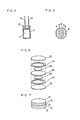
- Fig. 9 is a view showing a representative example of outside forming of the capacitor of this invention.
- the capacitor element comprised of polarizable electrodes 17 made of activated carbon cloth, conductive electrodes 18 and a separator 19 is enclosed in a pair of metal cases 20 making a pair with two pieces, to form a coin type capacitor.
- 21 is an insulative gasket ring for carrying out insulation and sealing between the metal cases 20, and with this invention gasket ring 21 inbetween the pair of metal cases 20 are connected. That is, each of the conductive electrodes 18 formed on the polarizable electrodes 17 electrically contacts the inside face of each of the metal cases 20, and in this embodiment the metal cases 20 become electrodes for output taking out.
- the polarizable electrodes are constituted by activated carbon fiber 23 carrying an electrode conductivity improving agent 22 such as conductive paint for raising conductivity.
- the conductivity improving agent 22 may be provided on the activated carbon fiber 23 not only on the face of the side of the conductive electrode 18, but also on the other face and on whole body.
- activated carbon fibers or carbon fibers are used as the polarizable electrode
- CD surface area per unit weight is large
- 2 electric resistance is small
- 3 mechanical strength is high
- 4 resistivity against chemicals is high.
- Conventional activated carbon powder has the properties of 1, 2 and 4, but the activated carbon powder and carbon fiber have, in addition to the above-mentioned, a mechanical strength as electrode 3 and is very effective material.
- Activated carbon fiber fulfilling such demand comprises four kinds, phenol kind (cured novolak fibers), rayon kind, acryl kind and pitch kind. Table 1 shows properties of these four kinds, activated carbon and coconut-granule activated charcoal.
- acryl kind and pitch kind generally somewhat lacks flexibility, and specific surface area is fairly small.
- rayon kind has a large specific surface area, its fiber is fragile; and though the felt type carbon fiber is popular, it is difficult to be made paper, and paper type is impossible, and it has problems in resistivity against chemicals and resistivity against water.
- the phenol kind carbon fibers utilize cured novolak fibers as material, and in the case of the phenol kind carbon fibers, because the cured novolak fibers are insoluble and have small heat shrinkage, there is no need of preliminarily making the material fiber insoluble, and the woven or non-woven cloth can be made into the activated carbon as they are. Besides they are strong and superior in flexibility, and therefore they are especially superior as polarizable electrodes of the capacitor.
- Activated charcoal which hitherto has been used as polarizable electrode of the capacitor has specific surface area of 300-3000 m 2 /g, and when considering the capacitance, in the case that mercury is used as polarizable electrode it is 20-40 pF/cm z . In theory, a large capacitance or 60-1200 F per 1 gr of the activated charcoal must be obtainable. However, in the conventional electric double layer capacitor, capacitance per unit weight of the activated charcoal has been taken out only 1/30-1/10 of the above-mentioned theoretical value.
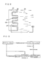
- Fig. 12 is a schematic chart of the electric double layer formed on surface of the activated charcoal.
- an electric field is applied between the activated charcoal substrate 24 and the electrolyte 25 contacting thereto, an electric charge is stored at the surface of the activated charcoal substrate 24, and the depth of the interface electric double layer is about 10A. Accordingly, as shown in Fig.
- the electric double layer is formed up to the inside of the micro-pore 26 and the electric double layer capacitance is stored up to the inside surface of the micro-pore 26, while for a micro-pore 27 of 20A or smaller no electric double layer is formed between its inside wall and the electrolyte.
- the utilization factor of the surface area becomes very bad.
- the specific surface area is large and besides there are many micro-pores having diameters of 20A or larger.
- Fig. 13 is a manufacturing process diagram of general activated carbon fibers. That is, there are a method that material fibers are directly made carbonized and activated, and a method that once the carbon fiber is made and subsequently it is activated. Such an activation of the carbon fibers (steps A and B in Fig. 11) is carried out in general in a mixed gas consisting of water vapor and nitrogen at a temperature of 700°C-800°C. Thereupon, when metal ions are co-existing in the material fiber during such an activation, the diameter of the micro-pores of the activated carbon fibers after activation can be controlled.
- micro-pores having inner diameters proportional to the diameters of metal ions used as a catalyst are formed.
- Metal ions suitable for the coexistence are of lithium, sodium, potassium, calcium, magnesium, zinc and so on, and when metal ions of the larger ion radius are used as catalyst, the micro-pores of the larger diameters are obtainable.
- salts chlorides, phosphates, nitrates, etc
- hydroxides of these metal ions are carried on the material fiber, to activate.
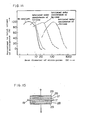
- Fig. 14 shows the pore size distribution of activated carbon fibers after activation, drawn individually for each catalyst used. As is shown, especially when salts or hydroxides of the alkali earth metals are used as the activation catalyst, the distribution rate of the micro-pores of diameters above 20A becomes large.
- the specific surface area is in inverse proportional relation to electric resistance and softness, and as the activation is done the surface area increases, carbonization yield decreases, resistance increases and it mechanically becomes fragile.
- the activation must proceed, until a large specific surface area is obtained. Then even though a satisfactory value as the capacitance value is obtained as a result, it makes a polarizable electrode with high resistance and weak mechanical strength.
- the surface area utilization factor very much improves, and hence there is no need of advancing the activation extremely to obtain a unit capacitance, and the activated carbon cloth obtained in this way as such has a low resistance and high strength. Furthermore, since the activated carbon fiber has a low resistance and a large diameter of the micro-pores, it has a feature that the internal resistance of the capacitor becomes very low.
- the ratio of the micro-pores of the diameter of 20A or more to the whole micro-pores when the total of the inside-surface area of the micro-pores is less than 1% of the total inside-surface area of the whole micro-pores, its special effect cannot be expected much, and in case the inside-surface area of the micro-pores of the inside diameter of 20A or more becomes 1% or more, its effect becomes prominent.
- Conductive electrodes used in this invention are conductive layers formed on the polarizable electrode directly by plasma spraying, arc spraying, vacuum deposition, sputtering, non-electrolytic plating, etc. Furthermore, metal foils with a conductive bond inbetween or conductive paints are suitable as the electrodes. Specially for strength, conductivity and easiness of forming, metal layers formed by plasma spray or arc spray method or metal foil with conductive bond inbetween are suitable as the electrodes.
- electrodes formed by the spray method is described.
- conductive material used here aluminum, nickel, copper, zinc, tin, lead, titanium, tantalum, and the like which are electro-chemically stable against electrolyte.
- Deposition weight by the spraying of 0.05 mg/cm 2- 500 mg/cm 2 is appropriate. In the case of another deposition method, this is not applicable.
- the electric resistance is high and a function as electrodes is not performed.
- the electrodes become too thick, and are likely to peel off or drop out from the carbon fibers or cracks are formed in the spray metal layer, and the mechanical strength becomes weak oppositely.
- polarizable carbon fiber electrodes having appropriate amount of collected sprayed layer comprise such mechanical strength and proper characteristic of the activated carbon, and besides in comparison with the case by the conventional paste method, handling in manufacturing is very easy. Resultingly, as will be described in the below-mentioned embodiment, a coin type flat sheet-shaped capacitor is obtainable.
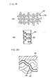
- a method by Fig. 15 is possible. That is, it is an electrode structure, wherein, a polarizable electrode 17 made of activated carbon fibers, a metal foil 29 of the same material as the sprayed metal, is provided with a conductive binder 28, for instance what is made by dispersing carbon, silver or copper in an organic resin such as epoxy resin, phenol resin, acryl resin, silicone resin, and so on.
- Conductive electrodes of this structure also, in case of application in the capacitor of, for instance, coin type flat sheet shape, electrically contact the conductive electrodes, as will be described in the below-mentioned embodiment.
- Futhermore as the conductive electrodes, they may be formed by applying conductive paint having conductive pulverized powders of silver, copper, carbon, or the like dispersed in organic resin.
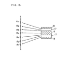
- Fig. 16 is a drawing to show the fundamental structure of a capacitor of the present invention comprising an electric conductivity improving agent 22, wherein when attention is paid to the internal resistance of the capacitor, with respect to a capacitor of a structure shown in Fig. 8 its internal resistance is divided into individual components as in Fig. 16. That is, these are a contact resistance R 1 between the conductive electrode 18 and a polarizable electrode 17, a resistance R 2 in the polarizable electrode 17 and an interface resistance R 3 between the polarizable electrode 17 and an electrolyte impregnating in the separator 19, a resistance R 4 of the electrolyte and R3, R2 and R ⁇ which exist in symmetry to these ones.
- the conductivity improving agent to be used here three kinds are considered: 1 oxides of transistion metals such as ruthenium, osmium, iridium, indium, plutinum, etc, 2 conductive paint made by dispersing carbon granules or other metal granules in organic resin or carboxy methyl cellulose or the like, 3 conductive metal layer of tin oxide or indium oxide formed by vapor deposition, sputtering or the like.
- 1 oxides of transistion metals such as ruthenium, osmium, iridium, indium, plutinum, etc
- 2 conductive paint made by dispersing carbon granules or other metal granules in organic resin or carboxy methyl cellulose or the like
- 3 conductive metal layer of tin oxide or indium oxide formed by vapor deposition, sputtering or the like 3 conductive metal layer of tin oxide or indium oxide formed by vapor deposition, sputtering or the like
- the activated carbon fibers are dipped in an aqueous solution of ruthenium chloride for a predetermined time and the above is thermally decomposed by keeping the aqueous solution of ruthenium cloride sufficiently soaking in the micro-pores in the activated carbon fiber, a layer of ruthenium oxide is coated to the inner wall of the micro-pores even to the extremely microscopic ones of the activated carbon fibers.
- a low resistance layer becomes to be formed on the surface of the activated carbon fibers 33.
- an electric double layer formed on the inside surface of the activated carbon fibers 33 is connected with low resistance to the conductive electrode 18 through the conductivity improving agent 22 formed on the surface.
- the resistance R 2 in the above-mentioned polarizable electrode namely the resistance in the activated carbon fibers, furthermore the contact resistance R 3 between the polarizable electrode and the electrolyte or the contact resistance R 1 between the polarizable electrode and the collector electrode also become small, and internal resistance of the electric double layer capacitor can be very much decreased.
- the conductivity improving agent is formed by using a thermally decomposable salt such as ruthenium salt
- electrode lead out of the micro-pores of activated carbon fibers can be easily made, and accordingly the surface area utilization factor of this part is also increased.
- forming methods of the conductivity improving agent to be used in this invention are as follows: 1 dipping and thermal decomposition of thermally decomposable salt such as ruthenium chloride, 2 painting or dipping method of carbon colloid solution, 3 forming by vacuum deposition of conductive oxide such as tin oxide.
- thermally decomposable salt such as ruthenium chloride
- 2 painting or dipping method of carbon colloid solution 3 forming by vacuum deposition of conductive oxide such as tin oxide.
- the electrolyte to be used in this invention comprises as its one component thereof, as least 1,2-dimethoxyethane.
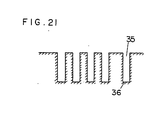
- Fig. 21 is a view showing micro-structure of the activated carbon fiber of phenol kind.
- the micro-pores to contribute to the formation of the electric double layer are the micro-pores of cylindrical shape with diameters of several tens A-several pm, and in order to effectively utilize the surface area of this micro-pores an electrolyte which can reach through at least the micro-pores of the diameter of several tens A-several pm to the bottom 36 of the micro-pores 35.
- 1,2-dimethoxyethane to be used in this invention is a dimethylether of ethyleneglycol, and dissolves in the water, alcohol and hydrocarbon, but is a stable liquid having the boiling point at 82°C-83°C.
- y-butyrolactone, tetrahydrofuran, dimethylformamide or propylene carbonate which has been hitherto used as solvent for electrolyte of electric double layer capacitor has poor permeability into the micro-pores because of its molecular radius or three dimensional hindrance due to having carbonyl group, amino group with methyl group or cyclic construction.
- the 1,2-dimethoxyethane are of low molecular number and has ether structure, hence substantially of straight chain type. Accordingly, the permeability into the micro-pore is superior than the conventional ones, and especially is effective in effective utilization of the surface area of the activated carbon fibers having cylindrical type micro-pores as above-mentioned.
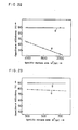
- Fig. 22 shows the capacitance efficiency (the capacitance efficiency to be referred to here is a value when considering only such micro-pores that have possibility of contributing to formation of electric double layers) which is to be taken out when activated carbon fibers of three types of specific surface areas (1000 m 2 /g, 1500 m 2 /g and 2000 m 2 jg) are used as polarizable electrodes, with respect to the case “a” where propylene carbonate is used as electrolyte solvent, the case “b” where both 1,2-dimethoxyethane and propylene carbonate are used in this invention. From Fig.
- Fig. 23 shows a relation between the surface area and the capacitance efficiency when coconut activated charcoal powders (300 m 2 /g, 500 m z /g and 700 m 2 /g) are used as the polarizable electrodes and propylene carbonate is used as the electrolyte. That is, when a low surface area material as the coconut activated charcoal granules is used as the polarizable electrode, even in the case "a", when propylene carbonate is used as the electrolyte solvent, it fairly serves the function. Also, as shown by the characteristic "b", even in case the low surface area material is used as the polarizable electrode, the effect of 1-2-dimethoxyethane is obtainable.
- the use of a vacuum impregnation method in permeating electrolyte into the activated carbon fiber is also an effective means. Furthermore, after forming conductive electrodes as cathode collector on graphite fibers of the novolak group by a means such as plasma spraying, an electrolyte containing a solvent consisting of propylene carbonate and 1,2-dimethoxyethane by the vacuum diffusion method is also effective.
- Capacitors of such structure are classified into the following two types. That is, they are of a first type having a unit capacitor element of a combination of polarizable electrodes and a separator, and of a second type having a unit capacitor element of a combination of one polarizable electrode, one separator and one non-polarizable electrode.
- Fig. 24 shows the fundamental structure drawing of the first type of multiunit capacitor element.
- a polarizable electrode 37 consisting of cloth, paper or felt of carbon fibers or activated carbon fibers, conductive electrode 38 formed on one side of the polarizable electrode 37 and a separator 39 soaked with electrolyte and disposed between the polarizable electrodes 37 constitute a composition which forms a unit capacitor element 40.
- the polarizable electrodes 37 are disposed in a mannerto form a margin part 40a whereat conductive electrodes 38 do not face each other.
- the conductive electrodes 38 functions as the collector electrode.
- n pieces of the unit capacitor elements 40 are, alternatively laminated as shown in Fig. 24, and metal layers 41, 42 are provided on both ends of the laminated body to form collected electrodes for outside leading out. At this time, it is more preferable to make an insulation between neighbouring unit capacitor elements 40 by putting an insulation spacer 43 or the like inbetween.
- Fig. 25 shows fundamental structure drawing of the second type of multiunit capacitor element.
- a combination body of polarizable electrodes 37 consisting of fabric, paper or felt of carbon fibers or activated carbon fibers and separators 39 soaked with electrolyte constitute a unitary capacitor element 44; and in this unitary capacitor element, in the polarizable electrodes 37 which are opposing with the separator 39 inbetween, the conductive electrode 38 having one polarizable electrode 37 formed thereon is disposed to the side of the separator 39.
- the unit capacitors 44 are as shown in Fig. 25, laminated of their n pieces with the separator 39 inbetween and on both sides of this laminated body, metal layers 41 and 42 are provided. Furthermore, also, also, in the unit capacitor element 44, margin parts 44a are provided on both ends, whereat conductive electrodes 38 of the polarizable electrodes 37 do not oppose each other,
- the conductive electrodes 38 function as collector electrodes, and the conductive electrodes 38 contacting the separator 39 function as non-polarizable electrodes, thereby constituting respective unit capacitor elements.
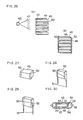
- a and B of Fig. 26 are cases of spraying metal powder 47 onto the main body 45 consisting of a laminated unit capacitor element group by using spraying gun 46.
- insulation spacers 43 may be provided in order that electrodes 48 and 49 of the neighbouring unit capacitor elements do not make conduction.
- Fig. 26B only electrodes designated by the hatching of the same direction are made contact with the sprayed electrodes 50.
- Fig. 27-Fig. 30 shows an example of completed state of this laminated type capacitor, and making in face bonding type as shown in Fig.
- metal lead wires 51 are disposed on both end faces of the main body 45 of the capacitor when sprayed electrode 50 is formed to be buried in the sprayed electrodes, or they are made in a manner that after forming the sprayed electrode 50 as shown in Fig. 29, the metal lead wires 51 are connected to the metal deposited electrodes 50 by silver paint or solder 52, can be considered. Covering is made for all of these by encapsulating the whole body into a case of resin, metal or ceramic, or dipping in the resin.
- FIG. 30 One example when the outside forming is made by a case is shown in Fig. 30, and in this example lead pieces 55, 56 are spot-welded on the inside face of two metal cases 53, 54 of disk shape, and the metal cases 53 and 54 are combined in such a manner that the capacitor main body 45 is encircled therewith and respective lead pieces 55, 56 of the metal cases 53, 54 are electrically connected to the sprayed electrodes 50 of the capacitor main body.
- 57 are insulation spacers to prevent direct contacting of the sprayed electrodes 50 of the main body 45 of the capacitor to the metal cases 53, 54; and 58 is a gasket for preventing contacting of the metal cases 53, 54 to each other.
- an aluminium layer 60 of thickness 5 ⁇ m is formed by the plasma spraying method.
- This double layer structure 61 is die-cut into disks having 2 cm diameter to provide an electrode body 62.
- Table 2 shows characteristics of trially made product of the same shape as the structure of Fig. 4, wherein activated charcoal paste is coated on the punching metal collector body and the structure of Fig. 6, for the sake of comparison.
- an aqueous solution of zinc chloride is soaked to be born. At this time, the amount of born NaOH is made to be 10% of the whole fiber weight.
- the fiber thus treated is kept in a furnace of 1000°C, to be carbonized and activated.
- activated carbon fiber cloths of three kinds of specific surface areas of 300 m z /g (30 min retention), 500 m 2 /g (1.5 hrs retention) and 1500 m 2 /g (3 hrs retention) are obtained.
- an aluminum metal layer of 50 pm thickness is formed by plasma spray method and thereafter is die-cut into circle-shaped ones of 5 mm diameter.
- an electrolyte of mixed solvent of propylene carbonate 30 wt% and y-butyllactone 70 wt% with addition of 10 wt% tetraethylammoniumperchlorate is soaked, and putting a separator made of polypropylene between two sheets of the electrodes, outside forming is made by using the cases of stainless steel and gasket.
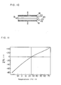
- Table 3 shows characteristics of a capacitor of this embodiment. Incidentally, the characteristics of the capacitor using an activated carbon cloth, activated without using the activation catalyst are also described for comparison in the same table. Furthermore, Fig. 32 shows the temperature characteristic (-25°C, 25°C and 70°C) of values of capacitance change rates AC of the capacitors using the activated carbon cloth of specific surface area 500 m 2 /g among the cases of both. (Embodiment 3)
- Cloth of activated carbon of thickness 0.2 mm woven by activated carbon fibers of novolak kind is dipped in an aqueous solution of ruthenium chloride of 0.5 mole/I for 5 min., and thereafter is retained in a furnace of 300°C to coat the surface of activated carbon fiber by ruthenium oxide layer. After forming an aluminum layer (20 um thickness) by plasma spraying method on the thus formed cloth of the carbon fibers, it is die-cut into circle-shape with diameter of 20 mm.
- a separator made of polypropylene is put and they are laminated, and as electrolyte mixed solution of propylene carbonate, y-butyrolactone and tetraethylammoniumperchlorate is injected, and they are encapsulated in metal cases with gasket inbetween.
- separator made of polypropylene is put and two sheets of the electrode bodies are laminated, and as electrolyte a mixed liquid of propylene carbonate, tetraethylammoniumperchlorate and y-butyrolactone is injected, and susequently outside forming is made by a gasket and metal cases.
- a tin oxide layer (thickness 5 pm) is formed by the vacuum deposition method on an activated carbon cloth of thickness 0.2 mm woven with activated carbon fibers of novolak kind. Furthermore, an aluminum layer (20 11m thickness) is formed thereon, and thereafter it is cut into circle shape of diameter of 20 nm to constitute the electrode body.
- a separator made of polypropylene between the electrode bodies, two sheets of the electrode bodies are laminated, and as electrolyte a mixed liquid of propylene carbonate and tetraethylammoniumperchlorate is injected and outside forming is made with a gasket and metal cases.
- Activated carbon cloth of thickness 0.2 mm woven with activated carbon fibers of novoiak kind is dipped in aqueous solution (0.5 mol/I) of ruthenium chloride for 5 min. Nextly, it is held in a thermal decomposition furnace of 300°C for 10 min, to form ruthenium oxide layer on a surface of the activated carbon fiber. On one face of the matter thus made, an aluminum layer (thickness 20 pm) is formed by the plasma spraying method, it is cut into squares of 3 cm x 3 cm to produce electrode bodies. As shown in Fig.
- these electrode bodies are laminated with separators made of polypropylene put inbetween, and thereafter wound to constitute a cylindrical capacitor body, and the capacitor body is enclosed in a cylindrical case of aluminum, and the opening part of the case is sealed with a rubber cap.
- 66 is an electrode body
- 67 is an aluminum layer
- 68 is a separator
- 69 is a lead wire
- 70 is a capacitor body
- 71 is a case and 72 is a rubber cap.
- activated carbon fiber cloth of diameter 2.0 cm of Japan Kynol Inc.
- aluminum conductive layer of thickness 5 ⁇ m is formed by plasma spray method.
- a solution prepared by mixing 1,2-dimethoxyethane 30 wt%, y-butyrolactone 50 wt% and tetramethylammoniumperchlorate 20 wt% is soaked.
- This two sheets of the activated carbon fiber cloths are laminated by putting a film of polypropylene of thickness 10 ⁇ m inbetween, and outside forming was made by outside case made of metal and gasket made of rubber.
- Table 5 shows the results of this embodiment.
- an aluminum conductive layer of thickness 5 ⁇ m is formed by the plasma spraying method.
- 10 sheets of what is made by cutting this in 10 mm square are laminated with separators as shown in Fig. 24 and Fig. 25.
- the separator used in this embodiment is of polypropylene film of thickness 10 pm, and in the separator and the activated carbon fiber cloth a solution prepared by mixing propylene carbonate 30 wt%, y-butyrolactone 50 wt% and tetramethylammoniumperchlorate 20 wt% as electrolyte is soaked.
- Table 6 shows comparing the characteristics of electric double layer capacitor made in accordance with the present embodiment and a conventional capacitor wound by using activated carbon powder in electrodes and a single layer capacitor using activated carbon fiber in electrode. (Embodiment 9)
- an aluminum foil of thickness 0.05 mm is bonded with a conductive bond of epoxy carbon.
- electrode bodies are obtained by die-punching this into circle shape of diameter 20 mm.
- This circle-shaped electrode bodies are laminated by putting a separator made of polypropylene inbetween, and mixed liquid of propylene carbonate, y-butyrolactone and tetraethylammoniumperchlorate as electrolyte is injected and outside forming is made with gasket and metal cases.
- polarizable electrodes are constituted with carbon fiber or activated carbon fiber and conductive electrodes are formed on the polarizable electrodes, accordingly such as effect is obtainable as the mechanical strength of the electrode parts becomes high, and small type capacitors in various shapes are obtainable, and furthermore capacitance per unit volume can be made large and besides the internal resistance and leak current can be made low.
Landscapes
- Engineering & Computer Science (AREA)
- Power Engineering (AREA)
- Microelectronics & Electronic Packaging (AREA)
- Chemical & Material Sciences (AREA)
- Materials Engineering (AREA)
- Electric Double-Layer Capacitors Or The Like (AREA)
Abstract
Claims (20)
Applications Claiming Priority (8)
| Application Number | Priority Date | Filing Date | Title |
|---|---|---|---|
| JP57114590A JPS594114A (ja) | 1982-06-30 | 1982-06-30 | 電気二重層キヤパシタ |
| JP114590/82 | 1982-06-30 | ||
| JP159849/82 | 1982-09-14 | ||
| JP57159849A JPS5948917A (ja) | 1982-09-14 | 1982-09-14 | 電気二重層キヤパシタ |
| JP177938/82 | 1982-10-08 | ||
| JP57177938A JPS5967617A (ja) | 1982-10-08 | 1982-10-08 | 電気二重層キヤパシタ |
| JP58013456A JPS59138327A (ja) | 1983-01-28 | 1983-01-28 | 電気二重層キヤパシタ |
| JP13456/83 | 1983-01-28 |
Publications (3)
| Publication Number | Publication Date |
|---|---|
| EP0112923A1 EP0112923A1 (fr) | 1984-07-11 |
| EP0112923A4 EP0112923A4 (fr) | 1986-06-05 |
| EP0112923B1 true EP0112923B1 (fr) | 1990-09-19 |
Family
ID=27455996
Family Applications (1)
| Application Number | Title | Priority Date | Filing Date |
|---|---|---|---|
| EP83902122A Expired EP0112923B1 (fr) | 1982-06-30 | 1983-06-30 | Condensateur a double couche electrique |
Country Status (4)
| Country | Link |
|---|---|
| US (1) | US4562511A (fr) |
| EP (1) | EP0112923B1 (fr) |
| DE (1) | DE3381893D1 (fr) |
| WO (1) | WO1984000246A1 (fr) |
Cited By (7)
| Publication number | Priority date | Publication date | Assignee | Title |
|---|---|---|---|---|
| US6643119B2 (en) | 2001-11-02 | 2003-11-04 | Maxwell Technologies, Inc. | Electrochemical double layer capacitor having carbon powder electrodes |
| US6955694B2 (en) | 2000-05-12 | 2005-10-18 | Maxwell Technologies, Inc. | Electrochemical double layer capacitor having carbon powder electrodes |
| US7722686B2 (en) | 2004-02-19 | 2010-05-25 | Maxwell Technologies, Inc. | Composite electrode and method for fabricating same |
| US7791861B2 (en) | 2003-07-09 | 2010-09-07 | Maxwell Technologies, Inc. | Dry particle based energy storage device product |
| US7791860B2 (en) | 2003-07-09 | 2010-09-07 | Maxwell Technologies, Inc. | Particle based electrodes and methods of making same |
| US7859826B2 (en) | 2005-03-14 | 2010-12-28 | Maxwell Technologies, Inc. | Thermal interconnects for coupling energy storage devices |
| US7920371B2 (en) | 2003-09-12 | 2011-04-05 | Maxwell Technologies, Inc. | Electrical energy storage devices with separator between electrodes and methods for fabricating the devices |
Families Citing this family (107)
| Publication number | Priority date | Publication date | Assignee | Title |
|---|---|---|---|---|
| US4626964A (en) * | 1984-03-19 | 1986-12-02 | Hitachi Maxell, Ltd. | Electrical double layer capacitor and production of the same |
| US4737889A (en) * | 1984-07-17 | 1988-04-12 | Matsushita Electric Industrial Co., Ltd. | Polarizable electrode body and method for its making |
| US4748542A (en) * | 1985-05-20 | 1988-05-31 | The Mead Corporation | Solid state electrochemical device |
| JPH07105316B2 (ja) * | 1985-08-13 | 1995-11-13 | 旭硝子株式会社 | 電気二重層コンデンサ用分極性電極及びその製造方法 |
| US4730239A (en) * | 1986-10-29 | 1988-03-08 | Stemcor Corporation | Double layer capacitors with polymeric electrolyte |
| US5649982A (en) * | 1987-05-21 | 1997-07-22 | Yardney Technical Products, Inc. | Process for manufacturing super capacitor |
| US5067927A (en) * | 1989-04-03 | 1991-11-26 | Hazenbroek Jacobus E | Revolving poultry thigh deboner |
| JPH0666229B2 (ja) * | 1989-08-30 | 1994-08-24 | いすゞ自動車株式会社 | 電気二重層コンデンサ |
| CA2023551C (fr) * | 1989-09-07 | 1994-05-10 | Ken Kurabayashi | Condensateur electrique a deux couches |
| JPH03234016A (ja) * | 1990-02-09 | 1991-10-18 | Isuzu Motors Ltd | 電気二重層コンデンサ |
| DE69128805T2 (de) * | 1990-03-29 | 1998-05-14 | Matsushita Electric Ind Co Ltd | Elektrolytischer Doppelschichtkondensator und Verfahren zu seiner Herstellung |
| US5426561A (en) * | 1992-09-29 | 1995-06-20 | The United States Of America As Represented By The United States National Aeronautics And Space Administration | High energy density and high power density ultracapacitors and supercapacitors |
| RU2099807C1 (ru) * | 1993-02-16 | 1997-12-20 | Акционерное общество "Элит" | Конденсатор с двойным электрическим слоем |
| US5581438A (en) * | 1993-05-21 | 1996-12-03 | Halliop; Wojtek | Supercapacitor having electrodes with non-activated carbon fibers |
| US6233135B1 (en) | 1994-10-07 | 2001-05-15 | Maxwell Energy Products, Inc. | Multi-electrode double layer capacitor having single electrolyte seal and aluminum-impregnated carbon cloth electrodes |
| US5621607A (en) * | 1994-10-07 | 1997-04-15 | Maxwell Laboratories, Inc. | High performance double layer capacitors including aluminum carbon composite electrodes |
| US5862035A (en) | 1994-10-07 | 1999-01-19 | Maxwell Energy Products, Inc. | Multi-electrode double layer capacitor having single electrolyte seal and aluminum-impregnated carbon cloth electrodes |
| JP3191941B2 (ja) * | 1995-04-27 | 2001-07-23 | 日本酸素株式会社 | 電気二重層キャパシタ用炭素材の製造方法並びに炭素電極および電気二重層キャパシタ |
| JPH10507881A (ja) * | 1995-08-14 | 1998-07-28 | アクチオネルノイ・オブチェストヴォ・ザクリトゴ・ティパ “エルトン” | 二層コンデンサー |
| US5600534A (en) * | 1995-10-12 | 1997-02-04 | Zbb Technologies, Inc. | Capacitor having non-conductive plastic frames |
| AU721291C (en) | 1996-05-15 | 2003-02-27 | Hyperion Catalysis International, Inc. | Graphitic nanofibers in electrochemical capacitors |
| US5874166A (en) * | 1996-08-22 | 1999-02-23 | Regents Of The University Of California | Treated carbon fibers with improved performance for electrochemical and chemical applications |
| US5849433A (en) * | 1997-03-10 | 1998-12-15 | Motorola, Inc. | Polymer blend electrolyte system and electrochemical cell using same |
| EP0917166B1 (fr) * | 1997-09-22 | 2007-08-01 | Japan Gore-Tex, Inc. | Condensateur électrique à double couche et son procédé de fabrication |
| EP0964416A4 (fr) * | 1997-11-11 | 2005-03-02 | Np Predpr Eksin | Condensateur a couche electrique double |
| US6225733B1 (en) | 1997-11-18 | 2001-05-01 | Corning Incorporated | Activated carbon electrodes for electrical double layer capacitors |
| CA2314970C (fr) | 1997-12-18 | 2007-03-06 | Science And Production Enterprise Inkar-M | Condensateur a couche electrique double |
| US6426862B1 (en) | 1997-12-18 | 2002-07-30 | Nauchno-Proizvodstvennoe Predpriyatie “Exin” | Capacitor with dual electric layer |
| US6042624A (en) * | 1998-04-03 | 2000-03-28 | Medtronic, Inc. | Method of making an implantable medical device having a flat electrolytic capacitor |
| RU2139587C1 (ru) * | 1998-04-17 | 1999-10-10 | Рязанский завод металлокерамических приборов | Способ изготовления конденсатора с двойным электрическим слоем |
| US6208502B1 (en) | 1998-07-06 | 2001-03-27 | Aerovox, Inc. | Non-symmetric capacitor |
| US6072692A (en) * | 1998-10-08 | 2000-06-06 | Asahi Glass Company, Ltd. | Electric double layer capacitor having an electrode bonded to a current collector via a carbon type conductive adhesive layer |
| US6222723B1 (en) | 1998-12-07 | 2001-04-24 | Joint Stock Company “Elton” | Asymmetric electrochemical capacitor and method of making |
| US6181546B1 (en) | 1999-01-19 | 2001-01-30 | Aktsionernoe Obschestvo Zakrytogo Tipa “Elton” | Double layer capacitor |
| US20030062259A1 (en) * | 1999-05-10 | 2003-04-03 | Naofumi Mushiake | Electrochemical device and process for manufacturing same |
| FR2793600B1 (fr) * | 1999-05-10 | 2001-07-20 | Europ Accumulateurs | Electrode de supercondensateur, supercondensateur et procede de fabrication |
| US6449139B1 (en) | 1999-08-18 | 2002-09-10 | Maxwell Electronic Components Group, Inc. | Multi-electrode double layer capacitor having hermetic electrolyte seal |
| EP1139356A4 (fr) * | 1999-09-13 | 2005-11-30 | Asahi Glass Co Ltd | Condensateur a double couche electrique |
| JP4527821B2 (ja) * | 1999-09-13 | 2010-08-18 | 日本碍子株式会社 | 電気化学キャパシタ |
| US6283985B1 (en) | 1999-12-01 | 2001-09-04 | Cardiac Pacemakers, Inc. | Reforming wet-tantalum capacitors in implantable defibrillators and other medical devices |
| US6706059B2 (en) * | 1999-12-01 | 2004-03-16 | Cardiac Pacemakers, Inc. | Reforming wet-tantalum capacitors in implantable medical devices |
| US6899967B2 (en) | 2000-04-10 | 2005-05-31 | Excellatron Solid State, Llc | Electrochemical conversion system |
| US6709778B2 (en) | 2000-04-10 | 2004-03-23 | Johnson Electro Mechanical Systems, Llc | Electrochemical conversion system |
| US6686076B2 (en) | 2000-04-10 | 2004-02-03 | Excellatron Solid State, Llc | Electrochemical conversion system |
| US6737180B2 (en) | 2000-04-10 | 2004-05-18 | Johnson Electro Mechanical Systems, Llc | Electrochemical conversion system |
| US6627252B1 (en) * | 2000-05-12 | 2003-09-30 | Maxwell Electronic Components, Inc. | Electrochemical double layer capacitor having carbon powder electrodes |
| JP2002025867A (ja) * | 2000-07-04 | 2002-01-25 | Jeol Ltd | 電気二重層キャパシタおよび電気二重層キャパシタ用炭素材料 |
| US7943250B1 (en) | 2000-07-28 | 2011-05-17 | Johnson Research & Development Co., Inc. | Electrochemical conversion system for energy management |
| US6687118B1 (en) | 2000-11-03 | 2004-02-03 | Cardiac Pacemakers, Inc. | Flat capacitor having staked foils and edge-connected connection members |
| US7456077B2 (en) | 2000-11-03 | 2008-11-25 | Cardiac Pacemakers, Inc. | Method for interconnecting anodes and cathodes in a flat capacitor |
| US6699265B1 (en) * | 2000-11-03 | 2004-03-02 | Cardiac Pacemakers, Inc. | Flat capacitor for an implantable medical device |
| US6509588B1 (en) | 2000-11-03 | 2003-01-21 | Cardiac Pacemakers, Inc. | Method for interconnecting anodes and cathodes in a flat capacitor |
| US6551533B1 (en) | 2000-11-28 | 2003-04-22 | Chemat Technology, Inc. | Method of forming fibrous materials and articles therefrom |
| DE10060653A1 (de) * | 2000-12-06 | 2002-06-20 | Epcos Ag | Elektrischer Doppelschicht-Kondensator |
| US6813139B2 (en) | 2001-11-02 | 2004-11-02 | Maxwell Technologies, Inc. | Electrochemical double layer capacitor having carbon powder electrodes |
| US20030107852A1 (en) * | 2001-12-11 | 2003-06-12 | Zheng Chen | Electrochemical capacitor having low internal resistance |
| US7960054B2 (en) * | 2002-01-10 | 2011-06-14 | Excellatron Solid State Llc | Packaged thin film batteries |
| US20070094865A1 (en) * | 2002-01-10 | 2007-05-03 | Ji-Guang Zhang | Packaged thin film batteries and methods of packaging thin film batteries |
| US20030133254A1 (en) * | 2002-01-16 | 2003-07-17 | Zheng Chen | Light-weight reinforced electreochemical capacitor and process for making the same |
| DE60201813T2 (de) * | 2002-02-07 | 2005-12-08 | Luxon Energy Devices Corp., Chutung | Zylindrischer Hochspannungs-Superkondensator und dessen Herstellungsverfahren |
| US6706079B1 (en) | 2002-05-03 | 2004-03-16 | C And T Company, Inc. | Method of formation and charge of the negative polarizable carbon electrode in an electric double layer capacitor |
| US7079377B2 (en) * | 2002-09-30 | 2006-07-18 | Joachim Hossick Schott | Capacitor and method for producing a capacitor |
| US20040240152A1 (en) * | 2003-05-30 | 2004-12-02 | Schott Joachim Hossick | Capacitor and method for producing a capacitor |
| JPWO2004051680A1 (ja) * | 2002-11-29 | 2006-04-06 | 本田技研工業株式会社 | 電気二重層コンデンサ用の分極性電極及び電気二重層コンデンサ用の分極性電極の製造方法並びに電気二重層コンデンサの製造方法 |
| US7006346B2 (en) * | 2003-04-09 | 2006-02-28 | C And T Company, Inc. | Positive electrode of an electric double layer capacitor |
| US7256982B2 (en) * | 2003-05-30 | 2007-08-14 | Philip Michael Lessner | Electrolytic capacitor |
| US6842328B2 (en) * | 2003-05-30 | 2005-01-11 | Joachim Hossick Schott | Capacitor and method for producing a capacitor |
| US7531267B2 (en) * | 2003-06-02 | 2009-05-12 | Kh Chemicals Co., Ltd. | Process for preparing carbon nanotube electrode comprising sulfur or metal nanoparticles as a binder |
| US20070122698A1 (en) * | 2004-04-02 | 2007-05-31 | Maxwell Technologies, Inc. | Dry-particle based adhesive and dry film and methods of making same |
| US20110165318A9 (en) * | 2004-04-02 | 2011-07-07 | Maxwell Technologies, Inc. | Electrode formation by lamination of particles onto a current collector |
| US20060147712A1 (en) * | 2003-07-09 | 2006-07-06 | Maxwell Technologies, Inc. | Dry particle based adhesive electrode and methods of making same |
| US7731765B2 (en) | 2004-02-20 | 2010-06-08 | Excellatron Solid State, Llc | Air battery and manufacturing method |
| US20080070087A1 (en) * | 2004-02-20 | 2008-03-20 | Excellatron Solid State, Llc | Non-volatile cathodes for lithium oxygen batteries and method of producing same |
| US10566669B2 (en) | 2004-02-20 | 2020-02-18 | Johnson Ip Holding, Llc | Lithium oxygen batteries having a carbon cloth current collector and method of producing same |
| US7901730B2 (en) * | 2004-04-26 | 2011-03-08 | Johnson Research & Development Co., Inc. | Thin film ceramic proton conducting electrolyte |
| US20050278915A1 (en) * | 2004-06-18 | 2005-12-22 | Vannatta Guy C Jr | Spray coating of cathode onto solid electrolyte capacitors |
| US7224575B2 (en) | 2004-07-16 | 2007-05-29 | Cardiac Pacemakers, Inc. | Method and apparatus for high voltage aluminum capacitor design |
| US7120008B2 (en) * | 2004-07-16 | 2006-10-10 | Cardiac Pacemakers, Inc. | Method and apparatus for capacitor interconnection using a metal spray |
| US8568921B1 (en) | 2004-08-18 | 2013-10-29 | Excellatron Solid State Llc | Regenerative ion exchange fuel cell |
| US20060090646A1 (en) * | 2004-11-04 | 2006-05-04 | Questair Technologies Inc. | Adsorbent material for selective adsorption of carbon monoxide and unsaturated hydrocarbons |
| US7327552B2 (en) * | 2005-05-09 | 2008-02-05 | Cardiac Pacemakers, Inc. | Method and apparatus for electrically connecting capacitor electrodes using a spray |
| MX2007016485A (es) | 2005-06-24 | 2008-03-11 | Universal Supercapacitors Llc | Colector de corriente para capacitores electroquimicos de doble capa electrica y metodo de fabricacion del mismo. |
| CA2612642A1 (fr) | 2005-06-24 | 2007-01-04 | Valery Pavlovich Nedoshivin | Electrode et collecteur de courant pour condensateur electrochimique ayant une double couche electrique et condensateur electrochimique ayant une double couche electrique formee al'aide de ceux-ci |
| WO2007001199A1 (fr) | 2005-06-24 | 2007-01-04 | Universal Supercapacitors Llc | Supracondensateur électrochimique hétérogène et procédé de fabrication |
| KR20080087782A (ko) * | 2005-10-11 | 2008-10-01 | 엑셀라트론 솔리드 스테이트 엘엘씨 | 리튬 배터리 제조 방법 |
| US7692411B2 (en) | 2006-01-05 | 2010-04-06 | Tpl, Inc. | System for energy harvesting and/or generation, storage, and delivery |
| US7864507B2 (en) | 2006-09-06 | 2011-01-04 | Tpl, Inc. | Capacitors with low equivalent series resistance |
| RU2483383C2 (ru) | 2006-11-27 | 2013-05-27 | ЮНИВЕРСАЛ СУПЕРКАПАСИТОРЗ ЭлЭлСи | Электрод для использования в электрохимическом конденсаторе с двойным электрическим слоем (варианты) |
| FR2909483B1 (fr) * | 2006-11-30 | 2009-02-27 | Centre Nat Rech Scient | Un condensateur electrochimique avec deux electrodes en carbone de nature differente en milieu aqueux |
| TWI332669B (en) * | 2006-12-22 | 2010-11-01 | Taiwan Textile Res Inst | Flexible supercapacitor and method for electrode fabrcation thereof |
| CA2677885C (fr) * | 2007-02-19 | 2014-05-06 | Universal Supercapacitors Llc | Collecteur de courant d'electrode negative pour condensateur electromecanique heterogene et procede de fabrication de celui-ci |
| US20080241656A1 (en) * | 2007-03-31 | 2008-10-02 | John Miller | Corrugated electrode core terminal interface apparatus and article of manufacture |
| US20080235944A1 (en) * | 2007-03-31 | 2008-10-02 | John Miller | Method of making a corrugated electrode core terminal interface |
| CN101420021B (zh) * | 2007-10-26 | 2011-07-27 | 清华大学 | 锂离子电池正极及其制备方法 |
| US20090239132A1 (en) * | 2008-03-20 | 2009-09-24 | Excellatron Solid State, Llc | Oxygen battery system |
| US8699207B2 (en) * | 2008-10-21 | 2014-04-15 | Brookhaven Science Associates, Llc | Electrodes synthesized from carbon nanostructures coated with a smooth and conformal metal adlayer |
| GB0905896D0 (en) * | 2009-04-06 | 2009-05-20 | Univ Belfast | Process for removing metals from hydrocarbons |
| DE102009054718A1 (de) * | 2009-12-16 | 2011-06-22 | Evonik Litarion GmbH, 01917 | Verwendung von N-Ethyl-pyrrolidon bei der Herstellung von Elektroden für Doppelschicht-Kondensatoren |
| JP2011206749A (ja) * | 2010-03-30 | 2011-10-20 | Daikin Industries Ltd | 通電装置および通電方法 |
| CN101894680B (zh) * | 2010-06-23 | 2012-08-29 | 万裕三信电子(东莞)有限公司 | 双电层电容器用电极片及双电层电容器的制备方法 |
| US8508916B2 (en) | 2010-10-13 | 2013-08-13 | Cooper Technologies Company | High voltage electric double layer capacitor device and methods of manufacture |
| US20150093640A1 (en) * | 2012-03-29 | 2015-04-02 | Sumitomo Electric Industries, Ltd. | Electrode material, and capacitor and secondary battery using said electrode material |
| WO2014083919A1 (fr) * | 2012-11-29 | 2014-06-05 | 株式会社村田製作所 | Dispositif de stockage de puissance |
| RU2522940C1 (ru) * | 2013-04-19 | 2014-07-20 | федеральное государственное автономное образовательное учреждение высшего профессионального образования "Национальный исследовательский ядерный университет МИФИ" (НИЯУ МИФИ) | Способ изготовления токоснимающей фольги и токоснимающая фольга суперконденсаторов |
| FR3028088B1 (fr) | 2014-11-03 | 2016-12-23 | Hutchinson | Electrodes conductrices et leur procede de fabrication |
| DE102016101801B4 (de) | 2016-02-02 | 2021-01-14 | Infineon Technologies Ag | Lastanschluss eines leistungshalbleiterbauelements, leistungshalbleitermodul damit und herstellungsverfahren dafür |
| CN112216518B (zh) * | 2020-09-15 | 2022-08-30 | 暨南大学 | 一种柔性锌离子混合电容器及其制备方法和应用 |
Family Cites Families (15)
| Publication number | Priority date | Publication date | Assignee | Title |
|---|---|---|---|---|
| DE553991C (de) * | 1932-07-01 | Lorenz Akt Ges C | Elektrischer Kondensator | |
| US1891080A (en) * | 1928-12-26 | 1932-12-13 | Harold I Danziger | Electrical condenser and method of making same |
| US2391686A (en) * | 1938-08-31 | 1945-12-25 | Bell Telephone Labor Inc | Electrical condenser and dielectric element |
| US2797373A (en) * | 1952-08-28 | 1957-06-25 | Sprague Electric Co | Metallized film capacitors |
| US3090705A (en) * | 1958-01-17 | 1963-05-21 | Tervakoski Osakeyhtio | Impregnated paper to serve as a dielectric, especially in condensers to improve their critical performance |
| US3419770A (en) * | 1967-02-08 | 1968-12-31 | Matsushita Electric Industrial Co Ltd | Metallized paper condensers |
| US3656027A (en) * | 1970-12-28 | 1972-04-11 | Standard Oil Co Ohio | Electrical capacitor having electrically-conductive, impervious connector |
| US3700975A (en) * | 1971-11-12 | 1972-10-24 | Bell Telephone Labor Inc | Double layer capacitor with liquid electrolyte |
| JPS5728940Y2 (fr) * | 1976-05-11 | 1982-06-24 | ||
| JPS6015138B2 (ja) * | 1979-01-25 | 1985-04-17 | 松下電器産業株式会社 | 電気二重層キャパシタ− |
| DK147218C (da) * | 1980-01-10 | 1984-11-05 | Peter Olaf Henk | Elektrisk akkumulator med blysaltholdig elektrolyt |
| JPS56114312A (en) * | 1980-02-14 | 1981-09-08 | Nichicon Capacitor Ltd | Double layer capacitor |
| JPS5712515A (en) * | 1980-06-26 | 1982-01-22 | Matsushita Electric Industrial Co Ltd | Electric double layer capacitor |
| JPS5717136U (fr) * | 1980-06-30 | 1982-01-28 | ||
| DE3215126A1 (de) * | 1982-04-23 | 1983-10-27 | Robert Bosch Gmbh, 7000 Stuttgart | Speicherelement fuer elektrische energie |
-
1983
- 1983-06-30 WO PCT/JP1983/000208 patent/WO1984000246A1/fr not_active Ceased
- 1983-06-30 DE DE8383902122T patent/DE3381893D1/de not_active Expired - Lifetime
- 1983-06-30 EP EP83902122A patent/EP0112923B1/fr not_active Expired
- 1983-06-30 US US06/584,608 patent/US4562511A/en not_active Expired - Lifetime
Cited By (9)
| Publication number | Priority date | Publication date | Assignee | Title |
|---|---|---|---|---|
| US6955694B2 (en) | 2000-05-12 | 2005-10-18 | Maxwell Technologies, Inc. | Electrochemical double layer capacitor having carbon powder electrodes |
| US6643119B2 (en) | 2001-11-02 | 2003-11-04 | Maxwell Technologies, Inc. | Electrochemical double layer capacitor having carbon powder electrodes |
| US6946007B2 (en) | 2001-11-02 | 2005-09-20 | Sony Corporation | Electrochemical double layer capacitor having carbon powder electrodes |
| US7791861B2 (en) | 2003-07-09 | 2010-09-07 | Maxwell Technologies, Inc. | Dry particle based energy storage device product |
| US7791860B2 (en) | 2003-07-09 | 2010-09-07 | Maxwell Technologies, Inc. | Particle based electrodes and methods of making same |
| US8072734B2 (en) | 2003-07-09 | 2011-12-06 | Maxwell Technologies, Inc. | Dry particle based energy storage device product |
| US7920371B2 (en) | 2003-09-12 | 2011-04-05 | Maxwell Technologies, Inc. | Electrical energy storage devices with separator between electrodes and methods for fabricating the devices |
| US7722686B2 (en) | 2004-02-19 | 2010-05-25 | Maxwell Technologies, Inc. | Composite electrode and method for fabricating same |
| US7859826B2 (en) | 2005-03-14 | 2010-12-28 | Maxwell Technologies, Inc. | Thermal interconnects for coupling energy storage devices |
Also Published As
| Publication number | Publication date |
|---|---|
| DE3381893D1 (de) | 1990-10-25 |
| WO1984000246A1 (fr) | 1984-01-19 |
| EP0112923A1 (fr) | 1984-07-11 |
| EP0112923A4 (fr) | 1986-06-05 |
| US4562511A (en) | 1985-12-31 |
Similar Documents
| Publication | Publication Date | Title |
|---|---|---|
| EP0112923B1 (fr) | Condensateur a double couche electrique | |
| US5955215A (en) | Bipolar electrode-electrolyte unit | |
| US6059847A (en) | Method of making a high performance ultracapacitor | |
| KR101031019B1 (ko) | 전이금속산화물 코팅층을 가지는 금속 전극의 제조 방법 및그에 의해 제조된 금속 전극 | |
| US10644324B2 (en) | Electrode material and energy storage apparatus | |
| US6714402B2 (en) | Microfabricated electrochemical device separators | |
| JPH0963905A (ja) | 電気二重層キャパシタおよびその製造方法 | |
| CN101849270A (zh) | 固体电解电容器及其制造方法 | |
| WO2007076073A2 (fr) | Condensateur électrochimique-électrolytique et son procédé de fabrication | |
| CN101226829B (zh) | 一种钽钌混和式电解电容器及其制备方法 | |
| JP4822554B2 (ja) | キャパシタ用発泡状ニッケルクロム集電体およびそれを用いた電極、キャパシタ | |
| US6614647B2 (en) | Low impedance electrochemical cell | |
| JPH08250380A (ja) | 分極性電極およびその製造方法 | |
| JPS6364890B2 (fr) | ||
| JP2001217149A (ja) | 電気エネルギー貯蔵装置及びその製造方法 | |
| KR100282671B1 (ko) | 에너지 저장장치 및 그의 제조방법(energy storage device and methods of manufacture) | |
| JP2507125B2 (ja) | 電気二重層キャパシタおよびその製造法 | |
| JPH0213925B2 (fr) | ||
| JP2001185452A (ja) | 電気二重層コンデンサおよびその製造方法 | |
| JPH0974052A (ja) | 分極性電極の製造方法 | |
| JP2001284177A (ja) | 電気二重層コンデンサ | |
| JPH06204085A (ja) | 電気二重層キャパシタおよびその製造方法 | |
| JPH0330974B2 (fr) | ||
| JP2005277346A (ja) | 電気二重層コンデンサ及びその製造方法 | |
| JP2000169127A (ja) | 固形状活性炭質構造体およびそれを用いた電気二重層コンデンサ並びにその製造方法 |
Legal Events
| Date | Code | Title | Description |
|---|---|---|---|
| PUAI | Public reference made under article 153(3) epc to a published international application that has entered the european phase |
Free format text: ORIGINAL CODE: 0009012 |
|
| 17P | Request for examination filed |
Effective date: 19840228 |
|
| AK | Designated contracting states |
Designated state(s): DE FR GB |
|
| A4 | Supplementary search report drawn up and despatched |
Effective date: 19860605 |
|
| 17Q | First examination report despatched |
Effective date: 19880226 |
|
| GRAA | (expected) grant |
Free format text: ORIGINAL CODE: 0009210 |
|
| AK | Designated contracting states |
Kind code of ref document: B1 Designated state(s): DE FR GB |
|
| REF | Corresponds to: |
Ref document number: 3381893 Country of ref document: DE Date of ref document: 19901025 |
|
| ET | Fr: translation filed | ||
| PLBE | No opposition filed within time limit |
Free format text: ORIGINAL CODE: 0009261 |
|
| STAA | Information on the status of an ep patent application or granted ep patent |
Free format text: STATUS: NO OPPOSITION FILED WITHIN TIME LIMIT |
|
| 26N | No opposition filed | ||
| REG | Reference to a national code |
Ref country code: GB Ref legal event code: 746 Effective date: 19960628 |
|
| REG | Reference to a national code |
Ref country code: GB Ref legal event code: IF02 |
|
| PGFP | Annual fee paid to national office [announced via postgrant information from national office to epo] |
Ref country code: FR Payment date: 20020610 Year of fee payment: 20 |
|
| PGFP | Annual fee paid to national office [announced via postgrant information from national office to epo] |
Ref country code: GB Payment date: 20020626 Year of fee payment: 20 |
|
| PGFP | Annual fee paid to national office [announced via postgrant information from national office to epo] |
Ref country code: DE Payment date: 20020702 Year of fee payment: 20 |
|
| PG25 | Lapsed in a contracting state [announced via postgrant information from national office to epo] |
Ref country code: GB Free format text: LAPSE BECAUSE OF EXPIRATION OF PROTECTION Effective date: 20030629 |
|
| REG | Reference to a national code |
Ref country code: GB Ref legal event code: PE20 |