EP0112938A2 - Dispositif pour commander le débit de liquides et bec de versage - Google Patents
Dispositif pour commander le débit de liquides et bec de versage Download PDFInfo
- Publication number
- EP0112938A2 EP0112938A2 EP82306668A EP82306668A EP0112938A2 EP 0112938 A2 EP0112938 A2 EP 0112938A2 EP 82306668 A EP82306668 A EP 82306668A EP 82306668 A EP82306668 A EP 82306668A EP 0112938 A2 EP0112938 A2 EP 0112938A2
- Authority
- EP
- European Patent Office
- Prior art keywords
- liquid
- liquid outlet
- sleeve
- conduit
- valve
- Prior art date
- Legal status (The legal status is an assumption and is not a legal conclusion. Google has not performed a legal analysis and makes no representation as to the accuracy of the status listed.)
- Withdrawn
Links
Images

Classifications
-
- B—PERFORMING OPERATIONS; TRANSPORTING
- B67—OPENING, CLOSING OR CLEANING BOTTLES, JARS OR SIMILAR CONTAINERS; LIQUID HANDLING
- B67D—DISPENSING, DELIVERING OR TRANSFERRING LIQUIDS, NOT OTHERWISE PROVIDED FOR
- B67D3/00—Apparatus or devices for controlling flow of liquids under gravity from storage containers for dispensing purposes
- B67D3/04—Liquid-dispensing taps or cocks adapted to seal and open tapping holes of casks, e.g. for beer
- B67D3/043—Liquid-dispensing taps or cocks adapted to seal and open tapping holes of casks, e.g. for beer with a closing element having a linear movement, in a direction perpendicular to the seat
- B67D3/044—Liquid-dispensing taps or cocks adapted to seal and open tapping holes of casks, e.g. for beer with a closing element having a linear movement, in a direction perpendicular to the seat and venting means operated automatically with the tap
Definitions
- This invention relates to liquid dispensers and more particularly to dispensers suitable for dispensing liquid from containers and controllers for such liquid dispensers.
- liquid dispensing is required in for instance a refrigerator where a store of cooled drinks such as water or cordial may be kept and some dispensing means is required on the outside of the refrigerator which will allow the contents of the container to be dispensed quickly and cleanly into for instance a glass, cup or other receptacle without having to remove the liquid container from the fridge.
- a store of cooled drinks such as water or cordial
- some dispensing means is required on the outside of the refrigerator which will allow the contents of the container to be dispensed quickly and cleanly into for instance a glass, cup or other receptacle without having to remove the liquid container from the fridge.
- Dispensers such as the one shown in Australian Patent Application No. 29594/77 are known but these are adapted only to dispense known quantities of liquids. This may be suitable when dispensing fixed quantities of spirits for instance but not suitable for dispensing liquids to fill a glass or receptacle without the danger of over filling it.
- the invention is said to reside in a liquid outlet controller including at least two conduits, a first conduit adapted to facilitate from an air inlet to an air outlet, air ingress therethrough and the second conduit adapted to facilitate liquid egress from a liquid inlet to a liquid outlet, only during air passage through the said first conduit and valve means to close each of the said conduits.
- the air inlet is adjacent the air outlet. Further the air inlet conduit may be positioned within the air outlet conduit so as for instance to make the inlet conduit coaxial with the outlet conduit.
- valve means may be actuated by a manually operated device and in a further embodiment the valve means may be actuatable automatically by means of a sleeve having at least one abutment surface, the sleeve being positioned about the second conduit and being resiliently biased in relation to the second conduit such that the valves are normally closed.
- the first conduit being the air inlet conduit
- this air inlet conduit may carry means to actuate each of the valve means. This may be arranged such that the first conduit, the air inlet conduit, sequentially actuates the air valve means and then further movement of the sleeve, and hence the first conduit, actuates the liquid valve means.
- the invention may be said to reside in a liquid dispenser adapted to be secured to an outlet of a liquid holding container to assist in pouring liquid from the container, the dispenser including a body having a passageway passing therethrough, one end of which is adapted to sealably engage around the outlet of the container, the other end of the passageway having in association therewith a control member, the control member being movable with respect to the body so that in a first position a liquid outlet control valve within the passageway is closed and an airlet control valve with a passageway through the liquid outlet control valve is closed, in the second sequential position from the first said position the air inlet control valve is opened with the liquid outlet control valve remaining closed and in a sequential third position from the second position both the liquid outlet control valve and the air inlet control valve are opened.
- control member may comprise a sleeve located about the body, the sleeve being resiliently biased such that both the air inlet control valve and the liquid outlet control valve are normally closed. Pushing on the sleeve such as with the rim of a glass, cup or other receptacle or from the edge of the filling aperture of a petrol tank would cause the sleeve to he moved such as to sequentially open the air inlet and then the liquid outlet control valve.
- barometric pressure upon the liquid already dispensed into the receptacle will be such as to prevent further dispensing of liquid from the receptacle provided air cannot be allowed into the receptacle and this will not occur as the liquid level in the receptacle is such that the air inlet is closed.
- any abutment on the sleeve will of course determine the final level of fluid to be achieved in the receptacle.
- a liquid outlet controller of this type may be provided on for instance a fuel tank where fuel is being dispensed in a liquid form into some other container such as a fuel tank or a lawnmower. It may also be provided as indicated earlier on a liquid container with a liquid outlet on the outside of a refrigerator so that pushing a glass up against the abutment on the spring loaded sleeve will cause dispensing to occur until liquid level has risen in the glass or receptacle to such an extent that the air inlet is blocked and liquid flow will stop, removal of the glass or receptacle then will cause the valves to reseat and seal again.
- one great advantage of the present invention is that by introducing the air at a position above the liquid outlet control valve, laminar flow or pseudo-laminar flow of the liquid out of the dispenser will occur which will prevent slugging and turbulent flow of the liquid.
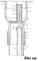
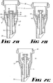
- FIG. 1A, B, and C of the drawings there is shown a portion of a liquid container 1 which has a screw threaded aperture 2 extending therefrom.
- a housing 3 is screwed and sealing means 4 prevents leakage of liquid between the housing and the screw threaded aperture.
- the housing 3 is tapered in the region 5 to provide a valve seating area 6 to be discussed further later.
- the housing 3 extends below the tapered portion 5 in a generally cylindrical manner and is further reduced in diameter at 7 to allow a sleeve 8 resiliently biased by compression spring 9 to slide in contact along the cylindrical portion 10 of the housing 3.
- the spring loaded sleeve also carries by means of an arm 11, an air inlet tube portion 12, which extends from being mounted on the sleeve up into the housing 3.
- a ring 13 fixed to the housing 3 supports the upper end of the air inlet tube portion 12.
- Flanges 14 mounted within the upper end of the tube 12 support a valve actuation rod 15 which extends further up within the housing 3.
- a valve member 16 seats against the valve sealing surfaces 6 to prevent liquid egress from the container in use.
- the valve member 16 has an extension 17 extending up into the upper portion of the housing 3 and it is up this extension 17 that the rod 15 passes to an upper end 18 of the extension upon which an air valve 19 is seated. Movement of the air valve 19 is by means of the rod 15. Movement of the rod 15 is guided within the extension 17 by means of flanges 20 on the rod 15.
- the sleeve 8 contains an abutment surface 21 and this abutment surface 21 includes raised portions 22 such that if the sleeve is inserted completely into the opening of a receptacle into which liquid is being dispensed, the abutments 22 allow air to depart from the receptacle being filled as liquid replaces it.
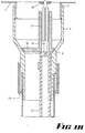
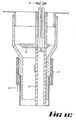
- This embodiment comprises a screw threaded aperture 30 suitable for fastening onto a liquid container of some sort. From this fastening 30 a housing 31 extends but in this embodiment the sleeve 32 is considerably larger and envelopes most of the housing 31.
- the liquid outlet 33 is formed into the lower end of the sleeve 32 and supports the air inlet tube 34.
- the liquid outlet valve 35 is essentially free floating but is held on its seat in 36 in a normally closed position by means of the helical spring 37 acting upon the sleeve 32,which acts on the liquid outlet valve 35 by means of the air inlet tube 34.
- the air inlet valve 38 is mounted on the upper end of the air inlet tube 34. At least one aperture 39 allows air ingress from the tube 34 into the space above the valve 35.
- the actual means for lifting the valve 35 are wings 40 affixed to the air inlet tube 34 which lift the valve upon movement upwards of the sleeve 32.
- Abutment means 41 are provided on the side of the sleeve 32 to facilitate compression of the spring 37 and hence opening of the valves 38 and 35 sequentially.
- the materials of construction of the liquid dispenser according to this invention may be of any suitable material and particularly plastics for the dispenser would be suitable and with the valve portions being made of a resilient rubber or plastics material.
- actuation of the air and liquid control valves may be by means of a manually operated lever with still the advantage that automatic cut-off of liquid flow will occur.
Landscapes
- Engineering & Computer Science (AREA)
- Mechanical Engineering (AREA)
- Details Of Rigid Or Semi-Rigid Containers (AREA)
- Closures For Containers (AREA)
- Devices For Dispensing Beverages (AREA)
Priority Applications (1)
| Application Number | Priority Date | Filing Date | Title |
|---|---|---|---|
| EP82306668A EP0112938A3 (fr) | 1981-06-15 | 1982-12-14 | Dispositif pour commander le débit de liquides et bec de versage |
Applications Claiming Priority (2)
| Application Number | Priority Date | Filing Date | Title |
|---|---|---|---|
| AUPE930781 | 1981-06-15 | ||
| EP82306668A EP0112938A3 (fr) | 1981-06-15 | 1982-12-14 | Dispositif pour commander le débit de liquides et bec de versage |
Publications (2)
| Publication Number | Publication Date |
|---|---|
| EP0112938A2 true EP0112938A2 (fr) | 1984-07-11 |
| EP0112938A3 EP0112938A3 (fr) | 1984-10-03 |
Family
ID=25642478
Family Applications (1)
| Application Number | Title | Priority Date | Filing Date |
|---|---|---|---|
| EP82306668A Withdrawn EP0112938A3 (fr) | 1981-06-15 | 1982-12-14 | Dispositif pour commander le débit de liquides et bec de versage |
Country Status (1)
| Country | Link |
|---|---|
| EP (1) | EP0112938A3 (fr) |
Cited By (18)
| Publication number | Priority date | Publication date | Assignee | Title |
|---|---|---|---|---|
| FR2608722A1 (fr) * | 1986-12-17 | 1988-06-24 | Fabrication Ind | Robinet de soutirage de produit liquide, a commande manuelle, admission d'air et fermeture automatique pour reservoirs divers |
| DE3731820A1 (de) * | 1987-09-22 | 1989-04-13 | Bosch Siemens Hausgeraete | Zapfventil, insbesondere zur ausgabe von getraenken |
| EP0422387A3 (en) * | 1989-09-05 | 1991-09-25 | Firma Alfred Kuehmichel | Filling funnel |
| US5118015A (en) * | 1989-09-05 | 1992-06-02 | Scholle Corporation | Method and apparatus for dispensing liquid |
| WO1999036349A1 (fr) * | 1998-01-16 | 1999-07-22 | Waddington & Duval Limited | Robinet a conduit d'air incorpore |
| WO2000002796A3 (fr) * | 1998-07-10 | 2000-04-20 | Wax Technology S A S | Appareil et procede de distribution de liquide a partir d'un reservoir |
| WO2001004042A1 (fr) * | 1999-07-12 | 2001-01-18 | Wax Technology S.A.S. | Dispositif distributeur d'un fluide contenu dans un recipient |
| EP1190985A3 (fr) * | 2000-09-26 | 2002-06-26 | Whirlpool Corporation | Distributeur de boissons pour réfrigérateurs ménagers |
| WO2003027547A3 (fr) * | 2001-09-28 | 2003-07-31 | Colder Prod Co | Clapet d'obturation pour un appareil d'administration de fluide |
| EP1466835A3 (fr) * | 2003-04-08 | 2006-05-17 | Sofiplast | Robinet d'arrêt avec bouton à pression pour carafes et similaires |
| NL1030454C2 (nl) * | 2005-11-17 | 2007-05-21 | Bravilor Holding Bv | Aftapkraan voor een drankreservoir alsmede drankreservoir voorzien van een dergelijke aftapkraan. |
| WO2009033277A1 (fr) | 2007-09-12 | 2009-03-19 | Vachon Leandre | Bec verseur à arrêt automatique autoventilé |
| US20110139829A1 (en) * | 2009-12-16 | 2011-06-16 | Techniplast | Filling device |
| US10472137B2 (en) | 2017-11-14 | 2019-11-12 | Le Groupe Dsd Inc. | Vented spout for a liquid storage container |
| US11479391B2 (en) | 2018-04-16 | 2022-10-25 | Le Groupe Dsd Inc. | Vented spout for a liquid storage container |
| US11713169B2 (en) | 2018-12-21 | 2023-08-01 | Le Groupe Dsd Inc. | Vented spout for a liquid storage container |
| US11827424B2 (en) | 2019-02-01 | 2023-11-28 | Le Groupe Dsd Inc. | Vented spout for a liquid storage container |
| WO2025162558A1 (fr) * | 2024-01-30 | 2025-08-07 | Aptar Freyung Gmbh | Fermeture de distribution pour un contenant et contenant pourvu d'une telle fermeture |
Family Cites Families (3)
| Publication number | Priority date | Publication date | Assignee | Title |
|---|---|---|---|---|
| US2272208A (en) * | 1939-01-28 | 1942-02-10 | Jorgensen Karl | Bottle filling mechanism |
| DE1182977B (de) * | 1963-06-12 | 1964-12-03 | Enzinger Union Werke Ag | Massfuellventil fuer Unterdruckfueller |
| US3207190A (en) * | 1964-01-03 | 1965-09-21 | Huffman Mfg Company | Battery filler |
-
1982
- 1982-12-14 EP EP82306668A patent/EP0112938A3/fr not_active Withdrawn
Cited By (28)
| Publication number | Priority date | Publication date | Assignee | Title |
|---|---|---|---|---|
| FR2608722A1 (fr) * | 1986-12-17 | 1988-06-24 | Fabrication Ind | Robinet de soutirage de produit liquide, a commande manuelle, admission d'air et fermeture automatique pour reservoirs divers |
| DE3731820A1 (de) * | 1987-09-22 | 1989-04-13 | Bosch Siemens Hausgeraete | Zapfventil, insbesondere zur ausgabe von getraenken |
| EP0422387A3 (en) * | 1989-09-05 | 1991-09-25 | Firma Alfred Kuehmichel | Filling funnel |
| US5118015A (en) * | 1989-09-05 | 1992-06-02 | Scholle Corporation | Method and apparatus for dispensing liquid |
| AU751491B2 (en) * | 1998-01-16 | 2002-08-15 | Waddington & Duval Limited | Tap with incorporated air passageway |
| US6401752B1 (en) | 1998-01-16 | 2002-06-11 | Waddington & Duval Limited | Tap with incorporated air passageway |
| WO1999036349A1 (fr) * | 1998-01-16 | 1999-07-22 | Waddington & Duval Limited | Robinet a conduit d'air incorpore |
| US6470910B2 (en) | 1998-01-16 | 2002-10-29 | Waddington And Duval Limited | Tap with incorporated air passageway |
| WO2000002796A3 (fr) * | 1998-07-10 | 2000-04-20 | Wax Technology S A S | Appareil et procede de distribution de liquide a partir d'un reservoir |
| WO2001004042A1 (fr) * | 1999-07-12 | 2001-01-18 | Wax Technology S.A.S. | Dispositif distributeur d'un fluide contenu dans un recipient |
| EP1190985A3 (fr) * | 2000-09-26 | 2002-06-26 | Whirlpool Corporation | Distributeur de boissons pour réfrigérateurs ménagers |
| WO2003027547A3 (fr) * | 2001-09-28 | 2003-07-31 | Colder Prod Co | Clapet d'obturation pour un appareil d'administration de fluide |
| US6916007B2 (en) | 2001-09-28 | 2005-07-12 | Colder Products Company | Closure valve apparatus for fluid dispensing |
| EP1466835A3 (fr) * | 2003-04-08 | 2006-05-17 | Sofiplast | Robinet d'arrêt avec bouton à pression pour carafes et similaires |
| NL1030454C2 (nl) * | 2005-11-17 | 2007-05-21 | Bravilor Holding Bv | Aftapkraan voor een drankreservoir alsmede drankreservoir voorzien van een dergelijke aftapkraan. |
| EP2285731A4 (fr) * | 2007-09-12 | 2012-04-18 | Leandre Vachon | Bec verseur à arrêt automatique autoventilé |
| US8561858B2 (en) | 2007-09-12 | 2013-10-22 | Le Groupe Dsd Inc. | Auto-vented automatic stop flow pouring spout |
| US8403185B2 (en) | 2007-09-12 | 2013-03-26 | Leandre Vachon | Auto-vented automatic stop flow pouring spout |
| WO2009033277A1 (fr) | 2007-09-12 | 2009-03-19 | Vachon Leandre | Bec verseur à arrêt automatique autoventilé |
| EP2336079A1 (fr) * | 2009-12-16 | 2011-06-22 | Techniplast | Dispositif de remplissage de récipients |
| FR2953818A1 (fr) * | 2009-12-16 | 2011-06-17 | Techniplast | Dispositif de remplissage |
| US20110139829A1 (en) * | 2009-12-16 | 2011-06-16 | Techniplast | Filling device |
| US8668121B2 (en) * | 2009-12-16 | 2014-03-11 | Techniplast | Filling device |
| US10472137B2 (en) | 2017-11-14 | 2019-11-12 | Le Groupe Dsd Inc. | Vented spout for a liquid storage container |
| US11479391B2 (en) | 2018-04-16 | 2022-10-25 | Le Groupe Dsd Inc. | Vented spout for a liquid storage container |
| US11713169B2 (en) | 2018-12-21 | 2023-08-01 | Le Groupe Dsd Inc. | Vented spout for a liquid storage container |
| US11827424B2 (en) | 2019-02-01 | 2023-11-28 | Le Groupe Dsd Inc. | Vented spout for a liquid storage container |
| WO2025162558A1 (fr) * | 2024-01-30 | 2025-08-07 | Aptar Freyung Gmbh | Fermeture de distribution pour un contenant et contenant pourvu d'une telle fermeture |
Also Published As
| Publication number | Publication date |
|---|---|
| EP0112938A3 (fr) | 1984-10-03 |
Similar Documents
| Publication | Publication Date | Title |
|---|---|---|
| EP0112938A2 (fr) | Dispositif pour commander le débit de liquides et bec de versage | |
| EP0147891B1 (fr) | Bec de versage | |
| CA2268237C (fr) | Bec anti-eclaboussures | |
| EP1212257B1 (fr) | Goulot verseur anti-deversement amovible | |
| US4314657A (en) | Measuring dispenser | |
| US5449029A (en) | Fill limit valve assembly | |
| BG64592B1 (bg) | Съд за съхраняване и дозирано наливане на напитки и по-специално на бира | |
| CN1112316C (zh) | 分配盖 | |
| WO2002030808A1 (fr) | Bouchon distributeur de fluide | |
| US4998571A (en) | Overfill valve apparatus | |
| US4712595A (en) | Magnetic safety funnel | |
| US4210262A (en) | Liquid dispensing apparatus with vent valve | |
| EP0445264A1 (fr) | Systeme et procede de dosage. | |
| US5277233A (en) | Overfill safety adapter | |
| US2469746A (en) | Filling device with receptacle operated outlet valve | |
| US2893444A (en) | Fluid handling device | |
| US6318604B1 (en) | Spill inhibiting spout | |
| AU698520B2 (en) | A measure | |
| US2578926A (en) | Automatic shutoff for filling spouts | |
| US4049162A (en) | Metering valve | |
| US4310038A (en) | Metering valve for beverage containers | |
| US3288179A (en) | Automatic nozzle with safety shutoff valve | |
| US6209567B1 (en) | Foam trap for beer or other gas propelled liquid dispensing systems | |
| US6499518B2 (en) | Nonoverflow, magnetic float valve assembly | |
| US3915357A (en) | Automatic vent valve |
Legal Events
| Date | Code | Title | Description |
|---|---|---|---|
| PUAI | Public reference made under article 153(3) epc to a published international application that has entered the european phase |
Free format text: ORIGINAL CODE: 0009012 |
|
| AK | Designated contracting states |
Designated state(s): AT BE CH DE FR GB IT LI SE |
|
| PUAL | Search report despatched |
Free format text: ORIGINAL CODE: 0009013 |
|
| RHK1 | Main classification (correction) |
Ipc: B67C 11/06 |
|
| AK | Designated contracting states |
Designated state(s): AT BE CH DE FR GB IT LI SE |
|
| 17P | Request for examination filed |
Effective date: 19841224 |
|
| 17Q | First examination report despatched |
Effective date: 19860305 |
|
| STAA | Information on the status of an ep patent application or granted ep patent |
Free format text: STATUS: THE APPLICATION IS DEEMED TO BE WITHDRAWN |
|
| 18D | Application deemed to be withdrawn |
Effective date: 19860716 |
|
| RIN1 | Information on inventor provided before grant (corrected) |
Inventor name: CLOUGH, RAYMOND JAMES |